Kenwood KVT-727DVD Service Manual
Monitor with dvd receiver
Hide thumbs
Also See for KVT-727DVD:
- Instruction manual (104 pages) ,
- Installation manual (72 pages) ,
- Installation manual (11 pages)
Table of Contents
Advertisement
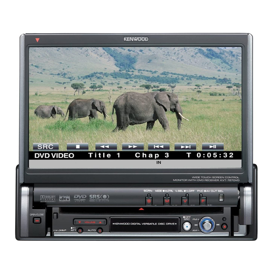
MONITOR WITH DVD RECEIVER
KVT-727DVD/727DVDY
SERVICE MANUAL
D I G I
T A L
DOLBY
CS Auto
SURROUND
OPEN/CLOSE
VOLUME
KENWOOD DIGITAL VERSATILE DISC DRIVE
TI
ATT
AUTO
Remote controller
(A70-2072-05 : RC-DV601)
Size AAA battery
Not supplied
Plastic cabinet assy
(A02-2723-03)
DC cord
(E30-6482-15)
WIDE TOUCH SCREEN CONTROL
MONITOR WITH DVD RECEIVER KVT-727DVD
SCRN
MODE
M.CTRL
V.SEL V.OFF
FNC
AV OUT SEL
S
M
V
F
OFF
SRC
Mounting hardware
(J22-0054-14) x2
Mounting hardware assy
Escutcheon
(B07-3082-02)
(J21-9823-03)
Cord with plug
DC cord
(E30-6483-05)
(E30-6474-15)
© 2005-8 PRINTED IN JAPAN
B53-0313-00 ( N ) 1073
TDF PANEL INFORMATION
MODEL
KVT-727DVD/727DVDY
Lever
Screw set
(D10-4674-04) x2
(N99-1753-05)
Cord with pinplug
(E30-6491-15)
Cord with plug
(E30-6485-05)
This product uses Lead Free solder.
TDF PANEL No.
TDF NAME
Y33-2330-61
TDF-727DVD
Wire band
(J61-0620-05) x2
Antena adaptor
(T90-0552-05)
Cord with connector
(E30-4938-25)
Advertisement
Table of Contents

Related Manuals for Kenwood KVT-727DVD


Summary of Contents for Kenwood KVT-727DVD
-
Page 1: Service Manual
B53-0313-00 ( N ) 1073 TDF PANEL INFORMATION MODEL TDF PANEL No. TDF NAME KVT-727DVD/727DVDY Y33-2330-61 TDF-727DVD WIDE TOUCH SCREEN CONTROL MONITOR WITH DVD RECEIVER KVT-727DVD SCRN MODE M.CTRL V.SEL V.OFF AV OUT SEL D I G I T A L DOLBY... - Page 2 KVT-727DVD/727DVDY NOTES ON ASSEMBLING THE MECHANISM 1. Fasten Screw A so that the interval (a) will be about 5.2mm and the interval (b) will be about 2.6mm. (The interval (a) can be measured using a pair of vernier calipers or similar tools.)
-
Page 3: Block Diagram
KVT-727DVD/727DVDY BLOCK DIAGRAM Complete view (X35- ) TOUCH TOUCH CONTROL TIMING CONTROLLER INVERTER CIRCUIT (X14- ) (X16- ) CHROMA SMALL GAMMA IC DISPLAY REMOTE CONTROL RGB SW SYSCON SDRAM RECEIVER CLOCK VIDEO OSCILLATOR ENCODER MPEG MECHA DECODER COMPOSITE FLASH SDRAM... - Page 4 KVT-727DVD/727DVDY BLOCK DIAGRAM X14-957 to X35 to X16 2DIN ONLY 1DIN ONLY 2DIN ONLY (X14-957 to MECHA to SUB PANEL /958) to SYSCOM from SYSCOM RL M+ EX M+ XDATA RL M- EX M- YDATA SW D from SYSCOM IC203...
- Page 6 KVT-727DVD/727DVDY BLOCK DIAGRAM X35-448 VR/VG/VB 2DIN TYPE 1DIN TYPE PON+5.0V PON+5.0V PON+5.0V PON-12.0V VGL-12.0V PON+5.0V PON+5.0V PON+3.3V 2DIN ONLY VGND VGND VGND VGND STV1 IC101 VGND VGND STV1 PON-12.0V 6.5 INCH UPSD SW+18.5V SW+18.5V OPEN U/D(UPSD) PON+18.5V DC-DC DGND DGND OPEN PON+12.5V...
-
Page 8: Components Description
KVT-727DVD/727DVDY COMPONENTS DESCRIPTION VIDEO CONTROL UNIT (X14-9572-71) Ref. No. Application / Function Operation / Condition / Compatibility IC100 DC-DC power supply IC SW5V/MECHA7V control IC101 DC-DC power supply IC SW3.3V/MECHA7.5V control BL8.5V, ±7V control IC102 DC-DC power supply IC IC103... - Page 9 KVT-727DVD/727DVDY COMPONENTS DESCRIPTION Ref. No. Application / Function Operation / Condition / Compatibility IC654 Video switch For switching composite signal from DVD composite signal and X34 IC701 Ope amp IC For audio LPF IC702 Regulator IC For audio 5V generation...
- Page 10 KVT-727DVD/727DVDY COMPONENTS DESCRIPTION Ref. No. Application / Function Operation / Condition / Compatibility Q203 PNP digital transistor For GREEN_LED control Q204 NPN digital transistor For RED_LED control Q205 PNP digital transistor For RED_LED control Q206 PNP digital transistor For resetting...
- Page 11 KVT-727DVD/727DVDY COMPONENTS DESCRIPTION SUB-CIRCUIT UNIT (X16-3032-71) Ref. No. Application / Function Operation / Condition / Compatibility IC201 Remote controller light receptor section Remote controller light receptor section Q101 For DSI signal switching DSI signal control Q206 For LED switching Switching LED_Red /LED_Green ELECTRIC UNIT (X34-3552-71) Ref.
- Page 12 KVT-727DVD/727DVDY COMPONENTS DESCRIPTION Ref. No. Application / Function Operation / Condition / Compatibility For fan 11V power supply Comes ON when Q2 is ON For fan 11V power supply Comes ON when Q3 is ON For fan 11V power supply...
- Page 13 KVT-727DVD/727DVDY COMPONENTS DESCRIPTION Ref. No. Application / Function Operation / Condition / Compatibility Q250 AM power supply SW Comes ON when AM source is selected Q252 For AM power supply Audio 8V is supplied when AM source is selected Converts IC413 µ-com controlled terminal voltage: 5V → 8V...
-
Page 14: Flash Rom
KVT-727DVD/727DVDY COMPONENTS DESCRIPTION Ref. No. Application / Function Operation / Condition / Compatibility IC10 Conversion of S/PDIF format data to digital audio format IC11 OP amp For audio signal amplification (Front) IC12 Analog switch Switching audio signal (Sub-woofer) and A4V... -
Page 15: Microcomputer's Terminal Description
KVT-727DVD/727DVDY MICROCOMPUTER’S TERMINAL DESCRIPTION System Microcomputer: 703265YGJ501A (X14: IC204) Pin No. Pin Name Module (physical) I/O Application Processing Operation Description AVREF0 AVSS AVREF1 V_MUTE VIDEO Video mute H: MUTE ON VIDEO Graphic µCOM FLMD0 REGC 4.953MHz µCOM RESET 32.768kHz VIDEO... - Page 16 KVT-727DVD/727DVDY MICROCOMPUTER’S TERMINAL DESCRIPTION Pin No. Pin Name Module (physical) I/O Application Processing Operation Description Chroma γ Access with chroma γ IC SCL/CHROMA_SCL BE_RST B/E circuit reset L: RESET POWER_DET Power supply 8.5V over current detection H: Abnormality detection BL_DET...
- Page 17 KVT-727DVD/727DVDY MICROCOMPUTER’S TERMINAL DESCRIPTION Pin No. Pin Name Module (physical) I/O Application Processing Operation Description OPEN_CLOSE/OPEN_CLOSE PANEL OPEN_CLOSE key (1DIN) L: ON OPEN_CLOSE/EJECT PANEL Tilt mechanism OPEN/CLOSE and eject (2DIN) L: ON PANEL Source key L: ON EJECT PANEL Eject key (1DIN)
- Page 18 KVT-727DVD/727DVDY MICROCOMPUTER’S TERMINAL DESCRIPTION Pin No. Pin Name Module (physical) I/O Application Processing Operation Description ILL_R PANEL Key ILLUMI red ON/OFF H: ON, L: OFF ILL_G PANEL Key ILLUMI green ON/OFF H: ON, L: OFF ILL_B PANEL Mini liquid crystal backlight blue ON/OFF...
- Page 19 KVT-727DVD/727DVDY MICROCOMPUTER’S TERMINAL DESCRIPTION Audio Microcomputer: 703068YGJ128A (X34: IC303) Module Truth Value Pin No. Pin Name Application Processing Operation Description (physical) Table DC_ERR IC2 VI DC offset detection Low at the detection Normal: 1.6V, TEL MUTE: 1V or lower, LINE_MUTE...
- Page 20 KVT-727DVD/727DVDY MICROCOMPUTER’S TERMINAL DESCRIPTION Module Truth Value Pin No. Pin Name Application Processing Operation Description (physical) Table AUD_SCL IC2 VI Clock for IC2 VI MUTE0 IC2 VI MUTE for IC2 VI OUT0 L: MUTE ON, H: MUTE OFF MUTE1 IC2 VI...
- Page 21 KVT-727DVD/727DVDY MICROCOMPUTER’S TERMINAL DESCRIPTION Module Truth Value Pin No. Pin Name Application Processing Operation Description (physical) Table 67,68 ON/OFF control from system control µ-com SYS_ON to X14 H: Box unit ON, L: Box unit OFF µCOM 70,71 XT2, XT1 µCOM GND2 µCOM...
- Page 22 KVT-727DVD/727DVDY MICROCOMPUTER’S TERMINAL DESCRIPTION Module Truth Value Pin No. Pin Name Application Processing Operation Description (physical) Table TV_SDATA Data from TV unit LX_DATA_S LX_M Data from slave unit LX_DATA_M LX_M Data to slave unit LX_CLK LX_M LX BUS clock VISUAL_SW5_1...
- Page 23 KVT-727DVD/727DVDY MICROCOMPUTER’S TERMINAL DESCRIPTION Module Truth Value Pin No. Pin Name Application Processing Operation Description (physical) Table OEM_TYPE0 Type OEM destination setting Refer to truth value table OEM_TYPE1 Type OEM destination setting Refer to truth value table µCOM ADCVDD µCOM...
- Page 24 KVT-727DVD/727DVDY MICROCOMPUTER’S TERMINAL DESCRIPTION i Video Selector 1 (MM1228XFBE) !2 Video Selector 4 (MM1503) VISUAL_SW1_1 VISUAL_SW1_2 Output VISUAL_SW4 Output AVIN1 Rear view SW3 (or NAVI) !3 Video Selector 5 (BA7652AF) o Video Selector 2 (MM1228XFBE) VISUAL_SW5_1 VISUAL_SW5_2 Output VISUAL_SW2_1 VISUAL_SW2_2...
- Page 25 KVT-727DVD/727DVDY MICROCOMPUTER’S TERMINAL DESCRIPTION Disc Controller Microcomputer: MN103S71F (X37: IC4) Pin No. Pin Name Application Pin No. Pin Name Application SW_2 8cm Ej-STOP, Lo-START detection OFS_TE CD TE offset cancel output SW_3 Lo-START detection DRV1 Drive output for spindle drive...
- Page 26 KVT-727DVD/727DVDY MICROCOMPUTER’S TERMINAL DESCRIPTION Pin No. Pin Name Application Pin No. Pin Name Application AVSSC VSS for analog NIORD ATAPI host read signal input PLFLT2 Condenser 2 for PLL IORDY Ready output to ATAPI host PLFLT1 Condenser 1 for PLL...
-
Page 27: Test Mode
KVT-727DVD/727DVDY TEST MODE Operation Specifications Compatible Models for This Test Mode Specification 1Din GRA 1Din OSD 2Din GRA 2Din OSD M707 DSP Exist DSP Exist DSP None DSP Exist DSP None DSP None KVT-817DVD KVT-717DVD DDX8017 DDX7017 KVT-M707 KVT-747DVD DDX7047... - Page 28 KVT-727DVD/727DVDY TEST MODE DC Offset Data Clear Information Screen By pressing the Clear key, the E2PROM DC Offset data is Below are display contents of the Information Screen. cleared. • Region Code • Serial No. • System µCom Version / Rom Correction Version / Type Chroma Screen •...
- Page 29 KVT-727DVD/727DVDY TEST MODE • Tact Key specifications are shown below. 1DIN (UNIT SP) 1DIN (BOX SP) 2DIN As usual As usual As usual VolUp As usual As usual As usual VolDw As usual As usual As usual Track (Seek) Up...
- Page 30 KVT-727DVD/727DVDY TEST MODE Screen Management section SCREEN Adjustment • Default is center. With one click, FullDown ↔ Center ↔ • While in the Test Mode (Including connection with special µ-com/jig), the startup will be with VIDEO screen. → Transi- FullUp.
- Page 31 KVT-727DVD/727DVDY TEST MODE • DVD audio/video confirmation (TDV-540A) For DVD video confirmation Title Chapter Audio Stream 1 Level Audio Stream 1 Audio Stream 1 Chapter Up/Dw AM/PM noise Audio Stream 1 Frequency characteristics Audio Stream 1 Color bar measurement Audio Stream 1...
- Page 32 KVT-727DVD/727DVDY TEST MODE Panel Mechanism Specification to turn motor driver ON with no slide • At FullOpen, angle is vertical and Slide is at the very back. mechanism • PanelMecha Slide/Angle will be in three steps. • In the condition where designation key is pressed down, •...
-
Page 33: Screen Specifications
KVT-727DVD/727DVDY TEST MODE Screen Specifications • During the Test Mode, when Graphic Screen is selected, Test Mode Main screen is displayed. Test Mode Main screen MECHA Chroma Chroma Source Set Up Audio Information Service Touch Chroma Hposi Auto Func screen... -
Page 34: Service Screen
KVT-727DVD/727DVDY TEST MODE Service Screen Serial Number Input Screen • Service information is displayed/cleared. • The serial number for each set is written. • EEPROM Chroma data is cleared. • DC Offset detection information is displayed/cleared. Serial Number Input Screen ∗∗∗... -
Page 35: Touch Screen
KVT-727DVD/727DVDY TEST MODE Touch Screen Hposi Screen • Touch variances in different sets are adjusted. • Horizontal position for each screen is adjusted. Touch the markers for three points in order. When EEPROM OK screen is displayed, adjustment is complete. - Page 36 KVT-727DVD/727DVDY TEST MODE Chroma Screen Source / Set Up / Audio Screen • Chroma data adjustment will be conducted. • The same as the normal screen (Other than Test Mode). • Adjustment is conducted with a remote controller (AudioSW). However, when SetUp key and Audio key are pressed, re- Note: Chroma data on the EEPROM can be cleared with turns to Test Mode Main screen.
-
Page 37: Adjustment Item
KVT-727DVD/727DVDY ADJUSTMENT Adjustment item 1. Chroma IC Adjustment Procedure (X14) 1. Chroma IC adjustment (X14) 1. While pressing on the [ATT] + [SRC] keys on the unit, reset (A remote controller is used for adjustment, while confirm- to enter the Test Mode. - Page 38 KVT-727DVD/727DVDY ADJUSTMENT Test Mode Adjustment Value Adjustment Item Adjustment Method Condition Display (Temporary) Gamma 1 CH : 11 Monitor waveform of 59 pin TP: VG of CN905 with an 3.0V±0.05V Input signal Adjustment oscilloscope and adjust the oscillation width of forward : None rotation-side pedestal and forward rotation-side Step 9.
- Page 39 KVT-727DVD/727DVDY ADJUSTMENT 2. OSD (On Screen Display) Clock and OSD_HSYNC Phase Adjustment (X14: VR361) Condition 3. Refer to Figure 1. Set video source: VIDEO Monitor IC400 11pin TP402 (HYSNC) and IC400 2pin TP403 Input: Video of NTSC (Video: Color bar) (OSC IN) with an oscilloscope.
- Page 40 KVT-727DVD/727DVDY ADJUSTMENT 3. Freerun Frequency Adjustment (X35: VR301) Measurement Location Adjustment Adjustment Method Timing controller 1DIN 2DIN Adjustment Value Location IC301 X35-448 X35-458 Set TP of NVD TP as no input NVD (21pin) TP363B TP55 and connect to PON3.3V. Set TP of NHD TP as no input and...
-
Page 41: Touch Panel Adjustment
KVT-727DVD/727DVDY ADJUSTMENT 3-2. DVD 6. Touch Panel Adjustment Insert TDV540 disk and, when a picture of an airplane ap- Adjustment Procedure pears, and press 4-key on the remote controller. (DVD Mode) 1. Press the Touch Key in the Menu screen of the Test Mode Then, Monoscope is displayed. - Page 42 KVT-727DVD/727DVDY PC BOARD (COMPONENT SIDE VIEW) VIDEO CONTROL UNIT X14-9572-71 (J76-0098-22) CN802 C118 C101 R803 DGND J960 R801 R813 W116 R805 CN904 IC202 IC203 SGND J100 R807 R809 C216 R103 D806 R118 D804 D801 R724 C108 D104 D853 L100 D807...
- Page 43 KVT-727DVD/727DVDY SUB-CIRCUIT UNIT X16-3032-71 A/2 (J76-0099-12) R104 D106 D105 D103 R107 R105 J960 D D D Q106 G S G Q101 CN101 R103 C108 Q129 Q100 X16 B/2 Q128 R162 R203 X14-9572-71 R201 W113 C154 Ref. No. Address Ref. No. Address...
- Page 44 KVT-727DVD/727DVDY PC BOARD (FOIL SIDE VIEW) VIDEO CONTROL UNIT X14-957/958x-xx (J76-0098-22) IC103 VIDEO CONTROL UNIT X14-9572-71 (J76-0098-22) W660 C127 D116 IC104 R100 W859 R114 R101 Q104 R119 R105 C126 R110 Q102 R112 R125 R126 CN851 IC651 R185 L111 R113 Q127 BU3.3V...
- Page 45 KVT-727DVD/727DVDY SUB-CIRCUIT UNIT X16-3032-71 A/2 (J76-0099-12) CN850 C851 J101 C802 D924 C803 W872 R867 X16 B/2 X14-9572-71 Ref. No. Address Ref. No. Address R372 IC100 Q105 R370 R371 C705 IC101 Q109 C713 IC362 IC102 Q110 IC103 Q111 W313 R366 IC104...
- Page 46 KVT-727DVD/727DVDY PC BOARD (COMPONENT SIDE VIEW) ELECTRIC VIDEO UNIT X35-4480-10 A/3 (J76-0101-02) X35 B/3 X16 B/2 CIRCUIT MODULEX X16-3130-00 A/2 (J76-0112-02) CN303 W301 W302 R348 C302 R302 R321 C304 D302 D304 Q303 IC303 C336 D303 R388 R325 C316 L306 C300...
- Page 47 KVT-727DVD/727DVDY PC BOARD (FOIL SIDE VIEW) ELECTRIC X35 B/3 VIDEO UNIT X35-4480-10 A/3 (J76-0101-02) X16 B/2 CIRCUIT MODULEX X16-3130-00 A/2 (J76-0112-02) C305 C330 +3.3V/+5.0V C335 L307 C329 STH2 C332 R352 R360 R350 R351 C314 W310 C317 C333 C310 R308 IC302...
- Page 48 KVT-727DVD/727DVDY PC BOARD (COMPONENT SIDE VIEW) ELECTRIC UNIT X34-3552-71 A/2 (J76-0104-12) J503 C511 Q500 C514 D508 IC405 C512 J502 R531 7 11 R543 R542 R541 R544 R532 R533 C515 R534 R548 R547 R546 R545 C513 D413 D514 D800 X300 R341...
- Page 49 KVT-727DVD/727DVDY D851 R515 Q500 IC501 D509 D510 R516 D508 R517 C507 R525 D512 D518 R518 J501 R541 D517 R526 R524 D515 J500 C501 R523 D514 D500 IC53 D516 X34 B/2 IC500 D519 R504 D502 C505 D520 C302 X34-3552-71 Ref. No. Address Ref.
- Page 50 KVT-727DVD/727DVDY PC BOARD (FOIL SIDE VIEW) ELECTRIC UNIT X34-3552-71 A/2 (J76-0104-12) R501 TP514 TP517 R519 TP516 R502 TP529 R520 R530 TP501 TP527 R528 TP528 R529 R500 R323 R856 X34 B/2 R855 R853 TP295 R854 TP294 R852 TP293 TP307 TP310 TP292...
- Page 51 KVT-727DVD/727DVDY TP549 R549 TP555 TP556 R554 TP557 R552 R553 TP548 R352 R354 R362 R801 TP310 TP311 X34-3552-71 R356 Ref. No. Address W801 TP250 TP251 TP252 TP253 R182 TP254 TP255 TP256 C164 TP257 C433 TP258 TP259 Q152 TP260 C420 Q200 Q201...
- Page 52 KVT-727DVD/727DVDY PC BOARD (COMPONENT SIDE VIEW) DAUGHTER UNIT X89-2740-10 (J76-0105-12) CN301 C319 R166 C320 IC19 IC20 R168 C326 C324 D302 D301 IC18 L301 L300 R126 C102 R128 IC10 R120 C312 IC17 R116 C311 C106 R151 L305 L304 C323 IC21 C322...
- Page 53 KVT-727DVD/727DVDY PC BOARD (FOIL SIDE VIEW) DAUGHTER UNIT X89-2740-10 (J76-0105-12) TP311 TP67 TP10 TP312 TP12 TP64 R301 W300 R303 Q300 Q303 R302 TP63 IC300 C301 Q302 TP66 L303 C110 R326 R305 R306 Q306 R119 C305 R155 R118 C303 R309 R310...
- Page 54 KVT-727DVD/727DVDY PC BOARD (COMPONENT SIDE VIEW) DVD UNIT X37-1070-00 (J76-0067-12) C107 C105 R102 R103 C108 C106 STDI R101 R100 C101 C102 C120 R120 R109 X37-1070-00 Ref. No. Address IC10 Refer to the schematic diagram for the values of resistors and capacitors.
- Page 55 KVT-727DVD/727DVDY PC BOARD (FOIL SIDE VIEW) DVD UNIT X37-1070-00 (J76-0067-12) PGND VHALF RFENV DVD LD R104 CD LD RFDIF0 WBLIN R122 CP10 CD ON JLINE R110 R117 R118 1.5V VHALF SW 3 SW 2 X37-1070-00 Ref. No. Address IC11 SWITCH UNIT X16-2380-00...
-
Page 56: Interconnection Diagram
KVT-727DVD/727DVDY INTERCONNECTION DIAGRAM DC CORD 8P (G)X14-955/956 (O)X14-957/958 VIDEO CONTROL UNIT DC CORD 8P (G)CN905 (O)CN850 CN301 DC CORD DC CORD 16PIN 8PIN KVT-817DVD KVT-827DVD E2 KVT-827DVDY KVT-837DVD KVT-847DVD KVT-867DVD KVT-717DVD KVT-747DVD KVT-627DVD E2 KVT-627DVDY KVT-737DVD KVT-747DVD KVT-767DVD KVT-727DVD E2 KVT-727DVDY... - Page 57 KVT-727DVD/727DVDY INTERCONNECTION DIAGRAM SPDIF CORD TO NAVIGATION TO TV TUNER SYSTEM LX-BUS KTC-V500 J502 J501 J502 J503 CORD 8P (E,E2 type) X89-274/279 DAUGHTER X34-355/381 UNIT X34-353/354 (DSP UNIT) ELECTRIC UNIT (AUDIO UNIT) CN150 CORD 8P (K,R,M,X,V type) J201 J202 J200...
- Page 58 KVT-727DVD/727DVDY VIDEO CONTROL UNIT (X14-95xx-xx) CN904 TP816 to IC701-7 DMIX L MIX-L ∗ TP817 to IC701-1 DMIX R MIX-R TP815 to IC650-28 DVD COMP COMP TP119 AGND AGND ∗ ∗ R814 75 CN101 CN802 CN850 5 4 3 2 1...
- Page 59 KVT-727DVD/727DVDY X35-A/3 X35-A/3 1DIN 2DIN -CN301 -CN303 11 12 13 14 16 17 18 19 20 21 22 23 24 25 26 27 28 29 30 31 32 33 34 35 36 38 39 40 41 42 43 44 45 46 47 48 49 50 51 52 53 54 55 56 57 58 59 60 61 62 63 64 65 ∗...
- Page 60 KVT-727DVD/727DVDY X35-B/3 -CN701 SW3.3V IC404 IC402 Q405 3.3V 3.3V 3.3V 3.3V CLR1 C424 3.3V CLR2 ∗ ∗ 0.01 Q404 W415 CN851 P101 3.3V 68 69 70 72 73 74 75 76 77 78 79 80 C422 0.1 3.3V 3.3V IC405 IC850 C419 0.1...
- Page 61 KVT-727DVD/727DVDY MOTOR-DRV. MOTOR-DRV. VCC1 TILT SLIDE Q216 C164 1000P R156 180u W881 470P CF102 Q109 IC100 0.8V 1.0V IC203 IC202 IC207 Q170 W882 CF103 1.0V C215 100u ∗ 0.01 3.2V 0.8V R147 BLGND 470P R163 C142 SW14V Q214 C162 1000P...
- Page 62 KVT-727DVD/727DVDY C218 0.01 SW3.3V Q120 Q215 Q122 Q207 R169 TP107 L103 Q206 180uH 470P W861 R164 R272 Q212 R168 Q124 Q121 Q219 R281 100K R271 R270 Q123 3.9K DC/DC CONVERTER SW5V MECHA7V DGND to IC601 L104 100uH W111 MECHA7V X201 32.768kHz...
- Page 63 KVT-727DVD/727DVDY TP200 TP201 SW3.3V NOT USED IC206 3.3V Q209 3.3V 3.3V IC200 to CN850-17 C205 Q208-B C213 0.01 Q208 C217 0.1 C206 ∗ LOGIC DGND (X14-95xx-xx) TYPE3 TYPE2 UNIT MODEL NAME IC201 R200 R201 R202 R203 R204 KVT-717DVD 70-10 KVT-737DVD...
- Page 64 KVT-727DVD/727DVDY SW2V DGND FLASH DGND IC520 TYPE2 TYPE1 TYPE0 C622 R203 R204 R205 R206 R207 3.3V VEE12 C623 VEE13 3.3V AUX0 AUX1 3.3V C624 AUX2 VSS18 3.3V VEE14 AUX3 L520 W608 AUX4 AUX5 W609 SW3.3V AUX6 AUX7 R625 NOT USED 4.7K...
- Page 65 KVT-727DVD/727DVDY SW2V W607 W606 DGND TP112 3.3V 2.0V 1.3V W115 IC108 R925 R926 1.5K C666 3.3V VEE9 VSS12 DGND L603 180 R629 100 DSCK R612 100 C613 R613 100 DCS0 3.3V VEE8 C632 VSS11 TP612 1000P DCS1 CP612 100 C667...
- Page 66 KVT-727DVD/727DVDY IC100-102 IC103 IC104 IC108 IC200 IC201 IC202,203 IC204 IC205 IC206 IC207 W658 R540 IC301 VGND IC303 IC540 IC304 R541 IC306,366, IC361 IC362 L540 TP540 IC363,364 10uH 3.3V IC365 1.25V SW3.3V W581 IC400 IC401 Q651 IC402 IC403 C673 IC405 1.25V...
- Page 67 (exposed parts are acceptably insulated from the supply circuit) before the appliance is returned to the customer. DGND • DC voltages are as measured with a high impedance voltmeter. Values may vary slightly due to variations between individual instruments or/and units. KVT-727DVD/727DVDY (1/5) X14-9572-71 (10/10)
- Page 68 IC201 R202 REMO SENSOR C202 R217 CN201 KVT-727DVD/727DVDY (2/5) ∗ ∗ to W02-5159- 5 MINI LCD CAUTION : For continued safety, replace safety critical components only with manufacturer’s recommended parts (refer to parts list). Indicates safety critical components. To reduce the risk of electric...
-
Page 69: Timing Controller
KVT-727DVD/727DVDY (X35-4480-10) (A/3) TP301A TP301B L105 CN301 TP321B L101 D103 D104 10uH W216 3.3uH P ON+5.0V PON5V TP302A TP302B P ON+5.0V L102 L104 D101 3.3uH 10uH W217 TP322B V GND 0-13.0V IC101 F100 V GND 0.63A 5.0V TP323B SW+18.5V 0-19.5V... - Page 70 KVT-727DVD/727DVDY (X35- ) (C/3) CN601 OPEN CN304 DGND D GND OZ964ISN-C S601 OPEN/CLOSE KEY IC101 LT1947-PBF OPEN/CLOSE KEY IC203 TA75W558FU-F D GND IC300 TC7WH126FU-F IC203 D GND D GND IC301 TC200G02G0104 VCOM AMP D GND LED GND IC302 TC7SH08FU-F R652...
- Page 71 GREEN LINE a high impedance voltmeter. Val- PHOT TR D.GND LINE D.GND ues may vary slightly due to varia- BLACK TILT DOWN SENSOR SLIDE PULSE SENSOR tions between individual instru- ments or/and units. T95-0253-05 KVT-727DVD/727DVDY (3/5) X35-4480-10 (3/3), X16-3130-00 (1/1)
- Page 72 KVT-727DVD/727DVDY to DC CORD (X34-3xxx-xx) (A/2) BU14V SW14V SW14V 3900u16 SURGE- 470K EXT AMP IC50 L MUTE 13.8V 8.3V 100K DSPA8V BU-DET ∗ 8.3V 13.8V IC51 ∗ P CON IC53 DSPD8V DSPD5V 1/2W 5.0V 8.5V DSPD5V P ANT BU5V BU5V...
-
Page 73: Power Amp
KVT-727DVD/727DVDY FRONT REAR CENTER CAMERA IN PRE OUT AV OUT VIDEO J200 J202 CN150 C235 C236 1000P 1000P C234 C237 R267 2200P 2200P 5V AMP 5V AMP 5V AMP IC200 IC201 IC202 R241 R242 D201 9.4V 9.4V 9.4V AOUT AOUT... - Page 74 KVT-727DVD/727DVDY X89- IC50,51,54 M5237ML-CF0J IC407,408 X89- IC52 ICL7660SIBAZ IC413,414 IC53 BA178M05T IC415 IC100 E-TDA7560A IC501 IC150,200-202 NJM4565V-ZB IC502 IC151 E-TDA7415 IC203,204,405,500 BA3121F Q2,4,12,15,51,5 CN150 CN151 1 2 3 4 5 6 7 10 11 12 13 14 15 16 17 18 19 20 21 22 23 24...
- Page 75 KVT-727DVD/727DVDY 407,408 MM1228XFBE-E Q57,59,60,64 2SB1565 D1-8 M1F60-5063 D152 UDZS16B VIDEO LINE 413,414 TC4052BFT 2SB1184 RM10ZLFNF D155,156 IMN10 MM1503-E DTC114EUA D10,11,13,14 1SR154-400 D201,206,210,504-507, SIGNAL LINE TC7SET04FU-F Q68,70 2SC4617 D12,18,100,101,157,200,203, 509-519,522-535,538,800 GND LINE TC7SH08FU-F Q69,151 2SA1774 204,212-214,216,414,503 STZ6.2N B LINE Q152 2SC2873-F...
-
Page 76: Audio Selector
KVT-727DVD/727DVDY (X34-3xxx-xx) C400, MODEL NAME UNIT No. A250 R365 R366 R369 R370 R371 R372 405,410 KVT-817DVD X34-3550-10 X86-3930-11 KVT-837DVD X34-3550-21 X86-3932-70 KVT-847DVD X34-3550-71 X86-3930-11 KVT-867DVD X34-3812-10 AV IN KVT-827DVD/827DVDY X34-3552-71 X86-3932-70 KVT-727DVD/727DVDY 34- ) (B/2) ∗ A250 IFGND R400 IF+B... - Page 77 D533 D530 D531 D532 P500 tomer. X14-RST • DC voltages are as measured with a high imped- ance voltmeter. Values may vary slightly due to variations between individual instruments or/and units. KVT-727DVD/727DVDY (4/5) X34-3552-71 (6/6)
- Page 78 KVT-727DVD/727DVDY (X89-27xx-xx) ∗ ∗ ∗ R165 8.2 W306 ∗ ∗ R167 8.2 W307 L.P.F ∗ 120P 8.0V TP70 8CH DAC TP71 R86 8.2 TP19 DVSS TP20 R85 8.2 TP21 DEM1 DVDD 0.8VRMS TP22 TP68 ROUT4 DEM0 3.3V TP72 TP69 LOUT4...
- Page 79 R306 100K CN301 GND LINE W300 400kHz C320 B LINE 1000P R308 C310 TP312 470P C324 1000P KVT-727DVD/727DVDY (5/5) (X89-27xx-xx) CN1, D8-10, R165, R166, W17, W306, MODEL NAME UNIT No. CN300 12,17 • DC voltages are as measured with DDX8017/8027/8027Y/8037/8047...
- Page 80 KVT-727DVD/727DVDY (X37-1070-00) TP106 C27 0.1 C3 0.1 1.4V 0.63Vp-p ON/OFF VREF1 VR DVD 1.7V VIN6 0.5Vp-p 2.2V 1.8V TP12 TP11 C5 1 DFLTOP VR CD CD E CD F 0.5Vp-p DFLTON VCC2 5.0V LD GND 2.2V TP19 VIN7(F) DPU1 VREF2 2.1V...
- Page 81 KVT-727DVD/727DVDY D3.3V 1.5V TP24 TP38 TP132 OFTR TP23 TP37 VHALF C120 AGND TP42 TP107 JLINE 0.022 TP20 TP21 TP39 TP41 FBAL C121 0.022 TP22 A3.3 D3.3V 3.3V C28 0.01 1.7V 3.3V TRCRS 3.3V AVDDC 3.1V C29 1 1.7V 16.897849MHz WBLIN 1.7V...
- Page 82 KVT-727DVD/727DVDY AN22022A-V AN41204A M29W400DB55N6E MN103S71F S-80829CNPF S-80813CNPF D3.3V NJM2880U115 1.5V IC10 NJM2886DL2-33 IC11 S-24CS04AFT FLASH ROM 16.897849MHz Q1,2 2SK3018 3.3V 3.3V P132 Q7,8 2SB0970 Q9,10 2SJ0536 Q11-14 DTA114YUA R45 1M 3.3V C120 D1,2 MAZS0510M 0.022 VSS1 MA4ZD03 C121 TP94 TP101...
-
Page 83: Exploded View (Dvd Mechanism)
KVT-727DVD/727DVDY EXPLODED VIEW (DVD MECHANISM) VFC1 (X16-2380) VPU1 φ1.4x3 N09-6143-05 (X37-) M1.7x2 N09-6144-05 φ1.7x4.3 N09-6145-05 M1.4x1.6 N09-6156-05 M1.7x1.6 N09-6230-05 WASHER N19-2192-04 M2x6 N09-6133-05 M2x7.3 N09-6134-05 M1.7x3.5 N09-6203-05 φ1.4x3.5 N09-6221-15 φ1.7x4.5 N09-6308-05 WASHER N19-2183-14 44 44 Parts with the exploded numbers larger than 700 are not supplied. -
Page 84: Exploded View (Main Unit)
KVT-727DVD/727DVDY EXPLODED VIEW (MAIN UNIT) M2.6x5 :N09-6167-05 φ2x5 :N09-6236-05 M2x3 :N09-6232-05 FLAT WASHER :N19-2022-04 φ2x6 :N80-2006-43 φ2.6x6 :N89-2606-48 M2x4 :N09-6374-05 (X35 C/3) PME1 FPC3 (X35-448 A/3) FPC1 LCD1 FPC2 FPC1 (X35 B/3) VME1 (X14-955) (X16 B/2) LCD2 (X16-303) Parts with the exploded numbers larger than 700 are not supplied. - Page 85 KVT-727DVD/727DVDY EXPLODED VIEW (DRIVE MECHANISM) M2.6X3.7 :N09-6062-15 M2X2.2(BLK) :N09-6063-25 M2X3.5(BLK) :N09-6064-25 M1.7X2.5 :N09-6065-25 M2X3.2 :N09-6066-25 M1.7X2.2 :N09-6111-25 (X16-B/2) WASHER :N19-2127-14 RETAINING RING :N29-0206-04 (X16-313 A/2) Parts with the exploded numbers larger than 700 are not supplied.
- Page 86 KVT-727DVD/727DVDY EXPLODED VIEW (HIDEAWAY UNIT / ACCESSORIES) SIZE AAA BATTERY (NOT SUPPLIED) (X89-274) (X34) (X34) A250 (X34 B/2) (X86) (X34-355) φ2.6x14 N84-2614-48 φ2.6x6 N89-2606-48 φ3x8 N89-3008-43 φ3x8 N09-6135-05 M3x20 N35-3020-48 Depends on the modles. Refer to the parts list. Parts with the exploded numbers larger than 700 are not supplied.
-
Page 87: Parts List
GEAR J21-9823-03 MOUNTING HARDWARE ASSY D13-2260-14 GEAR J21-9916-32 MOUNTING HARDWARE ASSY J21-9947-14 MOUNTING HARDWARE ASSY D13-2261-14 GEAR D13-2262-23 RACK (GEAR) J21-9949-14 MOUNTING HARDWARE D13-2263-14 GEAR J21-9984-14 MOUNTING HARDWARE ASSY E3 : KVT-727DVD E4 : KVT-727DVDY (Europe) Indicates safety critical components. - Page 88 CHIP C 0.10UF C306 CC73GCH1H270J CHIP C 27PF C118 CE32BM1C221M CHIP EL 220UF 16WV C307 CK73GB1H104K CHIP C 0.10UF C119-121 CK73GB1H104K CHIP C 0.10UF C309 CC73GCH1H180J CHIP C 18PF E3 : KVT-727DVD E4 : KVT-727DVDY (Europe) Indicates safety critical components.
- Page 89 CC73GCH1H100D CHIP C 10PF C906 CC73GCH1H101J CHIP C 100PF C429,430 CC73GCH1H020C CHIP C 2.0PF C918 CK73FB0J106K CHIP C 10UF C501 CK73GB1H104K CHIP C 0.10UF C926,927 CK73GB1H104K CHIP C 0.10UF E3 : KVT-727DVD E4 : KVT-727DVDY (Europe) Indicates safety critical components.
- Page 90 CHIP R 2.2K J 1/10W R170 RK73GB2A103J CHIP R J 1/10W R171 RK73GB2A563J CHIP R J 1/10W RK73GB2A473J CHIP R J 1/10W R172 RK73GB2A102J CHIP R 1.0K J 1/10W E3 : KVT-727DVD E4 : KVT-727DVDY (Europe) Indicates safety critical components.
- Page 91 CHIP R 100K J 1/10W R261 RN73GH1J102D CHIP R 1.0K D 1/16W R394 RN73GH1J303D CHIP R D 1/16W R262 RN73GH1J333D CHIP R D 1/16W R400 RK73GB2A103J CHIP R J 1/10W E3 : KVT-727DVD E4 : KVT-727DVDY (Europe) Indicates safety critical components.
- Page 92 0 OHM J 1/16W R669 RN73GH1J151D CHIP R D 1/16W W183 R92-1252-05 CHIP R 0 OHM J 1/16W R670 RK73GB2A103J CHIP R J 1/10W W201-203 R92-1252-05 CHIP R 0 OHM J 1/16W E3 : KVT-727DVD E4 : KVT-727DVDY (Europe) Indicates safety critical components.
- Page 93 ZENER DIODE IC405 TC7W08FU-F MOS-IC D501,502 DA204U DIODE IC406 TC7W32FU-F MOS-IC D650 STZ6.2N ZENER DIODE IC500 PQ070XH02ZPH ANALOGUE IC D701 DAP202U DIODE IC520 M29LV160T72U5 ROM IC IC540,541 TC7SHU04FU-F MOS-IC E3 : KVT-727DVD E4 : KVT-727DVDY (Europe) Indicates safety critical components.
- Page 94 2SC4081 TRANSISTOR R209 RK73GB2A472J CHIP R 4.7K J 1/10W Q214 DTA114TUA DIGITAL TRANSISTOR R214 RK73EB2E101J CHIP R J 1/4W Q215 2SC4081 TRANSISTOR R216 RK73GB2A104J CHIP R 100K J 1/10W E3 : KVT-727DVD E4 : KVT-727DVDY (Europe) Indicates safety critical components.
- Page 95 C60-62 CK73EB1E225K CHIP C 2.2UF C220 CK73GB1H103K CHIP C 0.010UF K CD04BA1C220M ELECTRO 22UF 16WV C221 CK73GB1H102K CHIP C 1000PF CK73EB1E225K CHIP C 2.2UF C222-224 CD04BJ1H100M ELECTRO 10UF 50WV E3 : KVT-727DVD E4 : KVT-727DVDY (Europe) Indicates safety critical components.
- Page 96 C425,426 CK73GB1A105K CHIP C 1.0UF C428 CK73GB1H104K CHIP C 0.10UF N09-6135-05 TAPTITE SCREW (3X8) C429-431 CK73GB1A105K CHIP C 1.0UF N35-3020-48 BINDING HEAD MACHINE SCREW C432 CD04BJ0J331M ELECTRO 330UF 6.3WV E3 : KVT-727DVD E4 : KVT-727DVDY (Europe) Indicates safety critical components.
- Page 97 RK73FB2B203J CHIP R J 1/8W R104,105 RK73GB2A103J CHIP R J 1/10W R224 RK73FB2B103J CHIP R J 1/8W R106 RK73GB2A223J CHIP R J 1/10W R225,226 RK73GB2A361J CHIP R J 1/10W E3 : KVT-727DVD E4 : KVT-727DVDY (Europe) Indicates safety critical components.
- Page 98 CHIP R J 1/10W R323 RK73GB2A104J CHIP R 100K J 1/10W R528 RK73EB2E4R7J CHIP R J 1/4W R324 RK73GB2A101J CHIP R J 1/10W R529 RK73EB2E681J CHIP R J 1/4W E3 : KVT-727DVD E4 : KVT-727DVDY (Europe) Indicates safety critical components.
- Page 99 D210 STZ6.2N ZENER DIODE 2SC4081 TRANSISTOR D211 STZ6.8N ZENER DIODE DTA123JK DIGITAL TRANSISTOR D212-214 DAP202U DIODE 2SA1576A TRANSISTOR D216 DAP202U DIODE 2SC4081 TRANSISTOR D218 STZ6.8N ZENER DIODE 2SB1443 TRANSISTOR E3 : KVT-727DVD E4 : KVT-727DVDY (Europe) Indicates safety critical components.
- Page 100 CHIP C 1500PF C337 CK73HB1C103K CHIP C 0.010UF K C93-1396-05 CHIP C 10UF 25WV C342 CC73HCH1H100D CHIP C 10PF CK73GB1H103K CHIP C 0.010UF K C401 CK73HB1H102K CHIP C 1000PF E3 : KVT-727DVD E4 : KVT-727DVDY (Europe) Indicates safety critical components.
- Page 101 RK73HB1J561J CHIP R J 1/16W RK73GB2A515J CHIP R 5.1M J 1/10W R385 RK73HB1J000JK CHIP R J 1/16W RK73GB2A104J CHIP R 100K J 1/10W R388 RK73HB1J000JK CHIP R J 1/16W E3 : KVT-727DVD E4 : KVT-727DVDY (Europe) Indicates safety critical components.
- Page 102 MOS-IC IC303 NJM2107F-ZB ANALOGUE IC C57,58 CK73HB0J105K CHIP C 1.0UF IC401 TPS850 ANALOGUE IC CK73HB0J105K CHIP C 1.0UF 2SC4081 TRANSISTOR C93-1228-05 CHIP C 1.0UF C62,63 CC73HCH1H120J CHIP C 12PF E3 : KVT-727DVD E4 : KVT-727DVDY (Europe) Indicates safety critical components.
- Page 103 CHIP R 4.7K J 1/16W R102,103 RK73HB1J202J CHIP R 2.0K J 1/16W R104 RK73HB1J103J CHIP R J 1/16W RK73GH2A123D CHIP R D 1/10W R105 RK73HB1J132J CHIP R 1.3K J 1/16W E3 : KVT-727DVD E4 : KVT-727DVDY (Europe) Indicates safety critical components.
- Page 104 CE32CL1C100M CHIP EL 10UF 16WV RK73EB2E101J CHIP R J 1/4W CK73GB1H104K CHIP C 0.10UF CK73GB1H104K CHIP C 0.10UF RK73GB2A470J CHIP R J 1/10W R75-82 RK73GB2A103J CHIP R J 1/10W E3 : KVT-727DVD E4 : KVT-727DVDY (Europe) Indicates safety critical components.
- Page 105 MOUNTING HARDWARE ASSY Q14,15 DTC643TU DIGITAL TRANSISTOR J22-0177-14 MOUNTING HARDWARE DVD MECHANISM ASSY (X92-5130-00) J90-1066-41 GUIDE A10-5084-31 CHASSIS J90-1067-13 GUIDE A10-5083-21 CHASSIS ASSY J90-1087-32 GUIDE A11-1631-21 SUB CHASSIS J90-1088-32 GUIDE E3 : KVT-727DVD E4 : KVT-727DVDY (Europe) Indicates safety critical components.
- Page 106 MACHINE SCREW N09-6221-15 MACHINE SCREW (P1.4X3.5) N09-6308-05 MACHINE SCREW (P1.4X4.5) N19-2183-14 FLAT WASHER T42-1321-05 MOTOR ASSY T42-1084-15 MOTOR ASSY X94-2000-00 MOTORASSY (LO) X94-2010-00 ROLLER ASSY VPU1 X94-2020-00 OPTICAL PICKUP ASSY E3 : KVT-727DVD E4 : KVT-727DVDY (Europe) Indicates safety critical components.
- Page 107 KVT-727DVD/727DVDY PARTS LIST CAPACITORS 2 2 0 • Capacitor value CC45 Color* 010 = 1pF 0 = 22pF 1 = Type ... ceramic, electrolytic, etc. 4 = Voltage rating 100 = 10pF 2 = Shape ... round, square, etc. 5 = Value...
-
Page 108: Specifications
Time alignment ........0~6.1m (5cm Step) Main unit ..............2.2kg Channel level ............... ±10dB Hideaway unit ............1.2kg KENWOOD follows a policy of continuous advancements in development. For this reason specifications may be changed without notice. US and foreign patents licensed from Dolby Laboratories.
Need help?
Do you have a question about the KVT-727DVD and is the answer not in the manual?
Questions and answers