Table of Contents
Advertisement
Quick Links
Advertisement
Table of Contents

Subscribe to Our Youtube Channel
Related Manuals for MFJ 223


Summary of Contents for MFJ 223
-
Page 2: Table Of Contents
Table of Contents ................1 1.0 Introduction 1.1 Features and Functions: ............1 1.2 Technical Specifications............2 ............... 4 1.3 Layout and Controls ..........5 2.0 Power Source and Initial Setup 2.1 Charging the Battery: ..............5 2.2 Processor Reset:...............5 2.3 Turning Analyzer On and Off: ...........6 2.4 Enter Call Sign or Name: ............6 2.5 Auto-Off Function: ..............7 2.6 System Screen:.................7... -
Page 3: Introduction
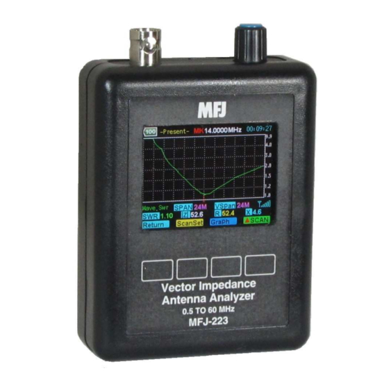
There's also a tunable marker on each screen you can use to call up precise numerical values for SWR, R, X, and Z at any point along the plot. The MFJ-223 has internal memory, so there's no need to worry about lost data -- if you turn your unit off, the last measurement will still be there when you turn it on again. -
Page 4: Technical Specifications
You'll find valuable information for setup and many important operating tips. Once you're up and running, you'll quickly discover the MFJ-223 has many user-friendly features including soft-menu labeling for the command keys and a built-in 8-page Help Menu. Don't forget to personalize the MFJ Boot Screen by entering your call letters or name. - Page 5 MFJ-223 Vector Impedance Antenna Analyzer Power Management Power Source: Built-in 3.7-V, 1800-mAh Lithium Polymer battery Charge Controller: Smart charger, LED charging-status indicator Voltage Monitor: On-screen DVM, plus battery condition icon Charger Source: Any USB port, analyzer accepts Micro-USB plug Power Savers: Auto-off timer, manual Run/Stop RF-...
-
Page 6: Layout And Controls
Boot Plots Counter 1. RF Connector: BNC-female. Use any SO-239-to-Male BNC adapter when testing with PL-259 connectors (MFJ-7708 or equivalent). 2. Rotary Encoder: Tunes DDS frequency when setting up tests, positions marker when reviewing plot data, and scrolls for some system set-up functions. -
Page 7: Power Source And Initial Setup
3.7-V 1800-mAH Lithium Polymer battery that comes pre- installed. To recharge, use a micro-USB-to-standard-USB patch cable (MFJ-5431 or equivalent). The analyzer can be recharged from any standard computer USB slot capable of delivering 5.0 volts at 500 mA. The analyzer's Micro-USB charging jack is located on the bottom of the unit. -
Page 8: Turning Analyzer On And Off
Press the Encoder Knob to move to the second character. Continue building the sequence until your call or name is entered. Press Exit to return to the MFJ Boot Screen and view your entry. MFJ Enterprises, Inc Version 1... -
Page 9: Auto-Off Function
2.7 Help Menu: To access the analyzer's eight-page Help Menu, bring up the MFJ Boot Screen and use the following procedure: Press the Help key to bring up the Help-Contents page Select a specific page using the S-Prev and S-Next... -
Page 10: Dds Frequency Entry
3.0 DDS Frequency Entry 3.1 Tuning: The MFJ-223 tunes continuously from 0.5 to 60 MHz with a choice of five tuning rates. All selection is done using the Encoder and Encoder Switch: Rotary Encoder: Rotate the encoder knob to change frequency. -
Page 11: Practicing Entry
MFJ-223 Vector Impedance Antenna Analyzer to round off the existing frequency before entering a new larger increment. For example, you might tune from 3.920 up to 4.000 MHz first, then switch to the 1-MHz step. Now the analyzer will step from 4.000 to 5.000 > 6.000 > 7.000...etc. Rounding off isn't mandatory, but some users find it helpful. -
Page 12: Single-Frequency Setup
MFJ-223 Vector Impedance Antenna Analyzer circuits or matching networks. Pressing Run/Stop again toggles the generator off. 4.2 S-Antenna Bar: The S-Antenna bar warns when your antenna is being energized by powerful external signals from a nearby transmitter. It also indicates when the analyzer's DDS generator is running, but its primary function is to detect interference when the generator is stopped. -
Page 13: Scan-Frequency Mode
MFJ-223 Vector Impedance Antenna Analyzer activated, a test signal will be generated. Note that the +5 dBm power level may be too high for some sensitive preamplifier or mixer stages and could damage them. The use of a wide-range step attenuator is strongly recommended when using the analyzer for any alignment procedure. - Page 14 MFJ-223 Vector Impedance Antenna Analyzer Mode Center Frequency Battery Status Elapsed Time Meter -Scan Set- CF 14.0000MHz 00:02:30 Tuning Step Measurement Scale Last Current Graph Span Span Page Interference Wave.SWR SPAN 1.2M VSPan 1.2M Detector Numerical Results Present Graph SCAN...
-
Page 15: Interference Detector
MFJ-223 Vector Impedance Antenna Analyzer 5.3 Interference Detector: The cell-phone style signal bars appearing in the lower right-hand corner of the screen warn of potential RF interference. Like the S-Antenna bar, they show deflection during scan runs, but the primary function is to warn of high interference levels with the DDS scanner is turned off. -
Page 16: Present Procedures
MFJ-223 Vector Impedance Antenna Analyzer Choose a convenient Tuning Step using the Encoder Switch. Set your desired Center Frequency (CF) using the Rotary Encoder. Scroll with the SPAN key while watching the SPAN box to select a scan width. To initiate the scan, press the SCAN command key. -
Page 17: Retrieving Data From Memory
6.0 Measurement and Accuracy Limitations 6.1 General: The MFJ-223 will serve as your eyes and ears when working with RF systems. However, all handheld analyzers share certain limitations, and being aware of them will help you to achieve more meaningful results. -
Page 18: Coupler Loss And Directivity: The
MFJ-223 Vector Impedance Antenna Analyzer 6.3 Coupler Loss and Directivity: Simple broadband couplers of the type used in the MFJ-223 may exhibit accuracy limitations, especially at the higher end of the analyzer's frequency range. Although accurate enough for amateur radio... -
Page 19: In Case Of Difficulty
If unit fails to operate properly, please check the suggestions below before contacting MFJ for service or replacement. Analyzer won't turn on: Battery may be fully discharged. Plug in to charger, confirm red charge light comes on, and check unit again after a couple hours. -
Page 20: Quick Start And Review Of Analyzer Functions
MFJ-223 Vector Impedance Antenna Analyzer 8.0 Quick Start and Review of Analyzer Functions: Charging: Accepts micro-USB plug on base of unit. Connect to USB port, charge until red LED turns green. Charge fully before first use. Turn On/Off: Press Encoder Knob down, wait for beep, and release. - Page 21 MFJ-223 Vector Impedance Antenna Analyzer Scan-Set Command Keys: Return exits to Boot Page. Present toggles analyzer to Present mode (shows data from the last scan completed). Span scrolls through available scan widths (see SPAN box for current selection). Scan activates the RF-generator sweep.
-
Page 22: Month Limited Warranty
MFJ Enterprises, Inc. Warrants to the original owner of this product, if manufactured by MFJ Enterprises, Inc. and purchased from an authorized dealer or directly from MFJ Enterprises, Inc. to be free from defects in material and workmanship for a period of 12 months from date of purchase provided the following terms of this warranty are satisfied. - Page 23 This warranty is given in lieu of any other warranty expressed or implied. 10. MFJ Enterprises, Inc. reserves the right to make changes or improvements in design or manufacture without incurring any obligation to install such changes upon any of the products previously manufactured.
Need help?
Do you have a question about the 223 and is the answer not in the manual?
Questions and answers