
Subscribe to Our Youtube Channel
Related Manuals for McIntosh MSE1


Summary of Contents for McIntosh MSE1
- Page 1 Owner’s Manual Surround Expander MSE1 McIntosh Laboratory, Inc. 2 Chambers Street Binghamton, New York 13903-2699 Phone: 607-723-3512 FAX: 607-724-0549...
-
Page 2: Technical Assistance
Data and Power Control Cable Part No. 170-202 Six foot, shielded 2 conductor, with 1/8 inch stereo mini phone plugs on each end. 2. For additional connection information, refer to the owner’s manual(s) for any component(s) connected to the MSE1 Surround Expander. Customer Service ã... -
Page 3: Important Safety Instructions
Safety Instructions IMPORTANT SAFETY or other outlet unless the blades can be fully in- serted to prevent blade exposure. INSTRUCTIONS! Attention: pour pevenir les chocs elecriques pas utiliser cette fiche polarisee avec un prolongateur, une prise de courant ou un autre sortie de courant, PLEASE READ THEM BEFORE sauf si les lames peuvent etre inserees afond ans en OPERATING THIS EQUIPMENT. - Page 4 Safety Instructions con’t, Introduction and Performance Features Introduction Care of Equipment: Performance Features · 24 Bit DSP Processing · 20 Bit Conversion Repair of Equipment: · Automatic Expansion Mode · LED Output Format / Delay / Volume Indicators · Adjustable Channel Time Delays ·...
- Page 5 Dimensions Dimensions " 44.45cm " " 9/16 3/16 Front View of the MSE1 9.00cm 10.60cm 17" 43.18cm " 7.00cm Rear View of the MSE1 " 33.65cm " 11/16 39.90cm " 37.1cm " 3/16 " 15/16 0.48cm Side View of the MSE1 7.47cm...
-
Page 6: Installation
Installation Installation " 1/16 43.34cm MSE1 Front Panel " 1/16 Custom Cabinet Cutout 7.80cm Cutout Opening for Custom Mounting Cabinet Front Panel MSE1 Side View in Custom Cabinet Cutout Opening for Ventilation Support Chassis " Shelf Spacers 2.54cm " "... - Page 7 Surround Loudspeakers The SUBWOOFer OUT- DATA IN jack receives control PUTS feed an audio signal to data from a McIntosh A/V Con- the input on a power ampli- trol Center and the DATA OUT fier for the optional second- jack provides the control data...
- Page 8 How to Connect with a MX132 Note: The MSE1 also has a BACK1 Output that provides a single Surround Back Channel that may be used in place of the BACK2 Output. McIntosh Powered Secondary Subwoofer (Optional) Note: The above step is necessary, as the Left and Right Surround Channels receive additional sound processing in the MSE1 Surround Expander.
- Page 9 To AC Outlet Left and Right Surround ¿ McIntosh Back Surround Power Amplifier 1 2 3 4 5 6 7 8 9 1 2 3 4 5 6 7 8 9 1 2 3 4 5 6 7 8 9...
- Page 10 How to Connect with a MX130/C39 and MSD4/ MAC-3 Note: The MSE1 also has a BACK1 Output that provides a single Surround Back Channel that may be used in place of the BACK2 Output. McIntosh Powered Secondary Subwoofer (Optional) Note: The above step is necessary, as...
- Page 11 To AC Outlet Left and Right Surround ¿ McIntosh Back Surround Power Amplifier 1 2 3 4 5 6 7 8 9 1 2 3 4 5 6 7 8 9 1 2 3 4 5 6 7 8 9...
- Page 12 Note: A six channel power amplifier may also be used in place of the five channel amplifier. Note: The MSE1 also has a BACK1 Output that provides a single Surround Back Channel that may be used in place of the...
- Page 13 To AC Outlet Left and Right Surround ¿ McIntosh Back Surround Power Amplifier 1 2 3 4 5 6 7 8 9 1 2 3 4 5 6 7 8 9 1 2 3 4 5 6 7 8 9...
-
Page 14: Manual Mode
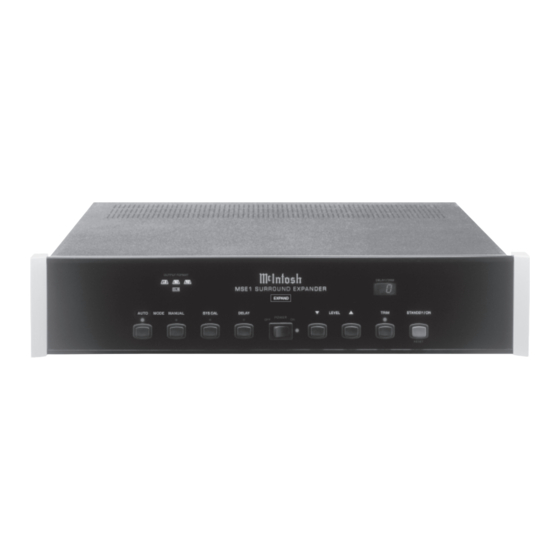
Level and Time Loudspeaker(s) Delay CHANNEL STATUS LED display Indicates when STANDBY/ON indicates which channels are active, the MSE1 is in push-button turns depending on the incoming signal; the Surround the MSE1 on and LS (Left Surround), BS (Back Sur- EXPAND Mode... - Page 15 Speaker Settings Speaker Settings Figure 1 Back 1 and 2 Selection Figure 3 Surround Speaker Size Note: If your system is using a Left and Right Back Surround Loudspeakers the actual signal sent to them is the same and is reduced in level by 3dB over a single Center Back Surround Loudspeaker Setup.
- Page 16 Surround Calibration Figure 5 Note: The MSE1 surround delay can be adjusted from 0 to 5ms. Each millisecond delay corresponds approximately to 1 foot in distance. Figure 4 Note: The table on the next page may be used to record your Delay Calibration Settings.
- Page 17 Note: A Surround Level Calibration Table, located on the next page, is provided to record your settings. Automatic System Calibration Manual System Calibration Note: The MSE1 Front Panel DELAY/TRIM Display will read “0” for each channel before any adjustments are Figure 6...
- Page 18 S u r r o u n d L e v e l C a l i b r a t i o n Surround Channel Default Setting New Setting Note: The MSE1 Front Panel DELAY/TRIM Display will read Left “0” for each channel before any adjustments are performed and the OUTPUT FORMAT LED’s will light Right to indicate which channel is reproducing the test signal.
- Page 19 Power On Auto Mode Note: The POWER Switch is only intended to be switched OFF when the MSE1 Surround Expander is not used for extended periods of time, like while away on vacation. During normal operation, the POWER Switch should stay in the ON position.
- Page 20 How to Operate the MSE1, con’t Delay Level p and q Note: The TRIM push-button needs to be pressed first, to activate the LEVEL push-buttons. Trim Figure 8...
- Page 21 MSE1 Notes...
-
Page 22: Specifications
Specifications Frequency Response Dimensions Weight Rated Output Output Impedance Maximum Output Voltage Total Harmonic Distortion Sensitivity Signal To Noise Ratio Maximum Input Signal Voltage Gain Power Requirements NOTE: Refer to the rear panel of the MSE1 for the correct voltage. - Page 23 Packing Instructions Packing Instructions...
Need help?
Do you have a question about the MSE1 and is the answer not in the manual?
Questions and answers