Table of Contents

Related Manuals for Sagem MA 500+ Series


Summary of Contents for Sagem MA 500+ Series
-
Page 1: Installation Guide
MorphoAccess 500 Series Installation Guide MA 500+ Series OMA 500 Series MA 500 Series Produced by Sagem Sécurité Copyright ©2009 Sagem Sécurité www.sagem-securite.com MorphoAccess 500 Series Installation Guide June 2009 SSE-0000053018-04... -
Page 2: Table Of Contents
INFORMATION ANADIAN INFORMATION GENERAL DESCRIPTION MA 500 / MA 500+ S ERIES OMA 500 S ERIES MA 500 / MA 500+ SERIES INSTALLATION PROCEDURE 1: D TAGE RILLING THE MOUNTING HOLES 2: M TAGE OUNTING THE METAL CHASSIS ASSEMBLY 3: C... - Page 3 APPENDIX 1 - FINGERPRINT PLACEMENT RULES APPENDIX 2 – RELATED DOCUMENTS DMINISTRATOR NFORMATION EVELOPER NFORMATION UPPORT OOLS APPENDIX 3 - DRILLING TEMPLATE MA500 / MA 500+ SERIES OMA 500 SERIES SUPPORT USTOMER SERVICE OTLINE SSE-0000053018-04 Sagem Sécurité document. Reproduction and disclosure forbidden.
-
Page 4: Introduction
To ensure the most effective use of your MorphoAccess™, we recommend that you read this Installation Guide thoroughly. The Sagem Sécurité logo and trademark are the property of Sagem Sécurité. All other trademarks or product names are trademarks or product names of the respective title holders. -
Page 5: Scope Of The Document
This guide relates to the use of MorphoAccess 500 Series terminals. MorphoAccess 500 Series is a generic appellation which gathers MorphoAccess terminals belonging to MA 500+ series, OMA 500 series and MA 500 series. Corresponding list of products is depicted in the table below. Contactless Smartcard False... -
Page 6: Safety Instructions
(see p16). Sagem Sécurité hereby declares that the MorphoAccess™ has been tested and found compliant with the following listed standards as required by the EMC Directive 89/336/EEC: EN55022 (1994) / EN55024 (1998), EN300-330 (1999) and by the low voltage Directive 73/23/EEC amended by 93/68/EEC: EN60950 (2000). -
Page 7: Usa Information
Responsible Party: Sagem Sécurité, Le Ponant de Paris, 27, rue Leblanc – F 75512 PARIS CEDEX 15 – FRANCE Changes or modifications not expressly approved by the party responsible for compliance could void the user’s authority to operate the equipment. -
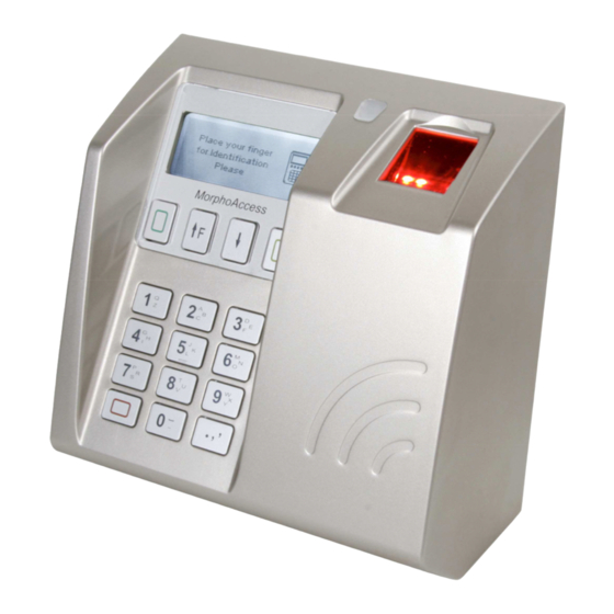
Page 8: General Description
Metal chassis MorphoAccess™ supplies: 1 Cover assembly with Chassis and 2 Secured screws for fixation, 1 Secured screwdriver Torx 20, 1 Chassis fixation kit (4 fixations and screws, 1 anti theft block). Sagem Sécurité document. Reproduction and disclosure forbidden. SSE-0000053018-04... - Page 9 Function keys Card reader Keyboard 4 Mounting slots Outdoor MorphoAccess™ supplies: 1 Cover assembly with chassis and protective visor, 1 Secured screwdriver Torx 10, 1 Chassis fixation kit (4 fixations and screws). SSE-0000053018-04 Sagem Sécurité document. Reproduction and disclosure forbidden.
-
Page 10: Ma 500 / Ma 500+ Series Installation Procedure
Drill the hole for the third screw in the center of the slot so that it is possible to correct the position later, if necessary. The mounting screws must be 5 mm diameter maximum. Sagem Sécurité document. Reproduction and disclosure forbidden. SSE-0000053018-04... -
Page 11: Stage 2: Mounting The Metal Chassis Assembly
Connect cables to terminal blocks with adequate torque conformed to screw dimensions (see the detailed instructions in the following sections) Be sure during manipulation that the power supply from the electrical source is off. SSE-0000053018-04 Sagem Sécurité document. Reproduction and disclosure forbidden. -
Page 12: Stage 3: Connecting The Chassis Assembly To The Cover Assembly
Position of the ribbon cable as the case is closed Cover assembly The ribbon cable must be folded as shown so that the case closes easily without damaging the cable Chassis assembly Sagem Sécurité document. Reproduction and disclosure forbidden. SSE-0000053018-04... -
Page 13: Stage 4: Closing Morpho Access
2. The cover is fitted onto the chassis by rotating it. Fit the two M4x16 assembly screws. Assembled Use screwdriver TORX 20 MorphoAcces SSE-0000053018-04 Sagem Sécurité document. Reproduction and disclosure forbidden. -
Page 14: Oma 500 Series Installation Procedure
Mounting hole location (rear view) Using the dimensional drawing in Appendix 3, drill holes for the four mounting bolts, vertically centered within the four slots. The mounting bolts must be 5 mm diameter maximum. Sagem Sécurité document. Reproduction and disclosure forbidden. SSE-0000053018-04... -
Page 15: Stage 2: Fixing
Fix the 4 mounting bolts (2 in upper zone , 2 in lower zone). Connect necessary cables to user wires (see the detailed instructions in the following sections). Mount protective visor with 4 screws and T10 screw driver. Put the 4 small caps. SSE-0000053018-04 Sagem Sécurité document. Reproduction and disclosure forbidden. -
Page 16: Electrical Interface
External +12V DC Terminal block reference Dataclock OUT Power Over Ethernet RJ45 Be sure during terminal installation and connections that Electric Static Discharge (ESD) is prevented by connecting installation man to ground security. Sagem Sécurité document. Reproduction and disclosure forbidden. SSE-0000053018-04... -
Page 17: Ma 500 Series : Old Terminal Block Board Wiring
Anti theft opto Wiegand IN RS422 / RS485 Anti theft switch Dataclock IN Power supply source Ethernet Wiegand OUT Ground External +12V DC Terminal block security Dataclock OUT reference Power Over Ethernet RJ45 SSE-0000053018-04 Sagem Sécurité document. Reproduction and disclosure forbidden. -
Page 18: Oma 500 Series Rear View And Cables
In order to comply with EMC directives (See p 6), all cables coming from Access Control system must be shielded. Both shield wires (cable, AC system cable ) must be tied together. Shield wire from cable is the wire without insulation. Sagem Sécurité document. Reproduction and disclosure forbidden. SSE-0000053018-04... - Page 19 If troubleshooting, please check that internal connections are similar to the following image: (I/O Board version 2) SSE-0000053018-04 Sagem Sécurité document. Reproduction and disclosure forbidden.
-
Page 20: Usb Flash Drive Installation
USB Flash drive installation has to be done when power is on. USB Flash drive has to be plugged on the upward USB connector, as on the following image: Sagem Sécurité document. Reproduction and disclosure forbidden. SSE-0000053018-04... -
Page 21: W F Usb
™ ™ Only Sagem Sécurité WI-FI™ USB dongle (Reference 189930722) may be installed into the terminal for WLAN (Wireless Local Area Network) operation. WI-FI™ USB dongle has to be plugged on the upward USB connector, as on the following image: SSE-0000053018-04 Sagem Sécurité... -
Page 22: Power Supply Source
For a higher susceptibility level, we recommend to the installer to connect a "ground connection" to the terminal. MA 500 / MA 500+ Series: A cable terminal connected to "ground security reference" must be tied to the fixation designed for (see p. 16-17). -
Page 23: Wiegand Output Wiring
MA 500 / MA 500+ Series OMA 500 Series Wiegand Dataclock cable Block 1 Wiegand D0 Green Block 2 Wiegand D1 White Block 3 LED1 Wiegand LED IN 1 (option) Brown Block 4 LED2 Wiegand LED IN 2 (option) Grey... -
Page 24: Wiegand Input Wiring
MA 500 / MA 500+ Series OMA 500 Series Wiegand Block 1 Wiegand D0 Blue Block 2 Wiegand D1 Yellow Block 3 Wiegand LED OUT 1 (option) Orange Block 4 +12V 12 Volts Power output (150mA max) Block 5 Ground for Wiegand... -
Page 25: Data Clock Input Wiring
MA 500 / MA 500+ Series OMA 500 Series Wiegand Data (5V TTL) Block 1 Blue Block 2 Clock (5V TTL) Yellow Block 3 Block 4 +12V 12 Volts Power output (150mA max) Block 5 Ground for Dataclock Black Note A: In case of old I/O board (split power connector) and if your... -
Page 26: Com Rs422 Serial Port
MA 500 / MA 500+ Series OMA 500 Series COM RS422/RS485 cable Block 1 Ground for RS422 Grey or White Block 2 RS422 Negative Transmit Orange Block 3 RS422 Positive Transmit Orange/White Block 4 RS422 Negative Receive Green Block 5... -
Page 27: Ethernet Wiring
2 ways for Ethernet wiring: - Terminal block connection (MA 500 / MA 500+ Series) only MA 500 / MA 500+ Series OMA 500 Series Ethernet cable Block 1 Receive negative Ethernet RJ45 Pin 6 Block 2 Receive positive Ethernet... -
Page 28: Output Relay And Security Switches
This terminal is part of security system. In order to prevent unauthorized access into this terminal it is the customer’s responsibility to connect the tamper switch and the anti theft switch (MA 500 / MA 500+ Series only) to the physical access controller (connected mode). - Page 29 (not available with OMA 500 Series). Terminal on wall: Anti theft switch ON Terminal out wall: Anti theft switch OFF “Security Loop” connection example: TSW1_0 TSW1_1 ATSW1_0 ATSW1_1 "Security Loop" Physical Access Controler SSE-0000053018-04 Sagem Sécurité document. Reproduction and disclosure forbidden.
- Page 30 Inductive charge management require a parallel diode for a better contact lifetime. Connection example about electrical door lock focus: ( < 30 V ) Overswing Electrical Door Diode Lock Pin 1 MorphoAccess™ Backside door MA500 Series button Pin 3 Sagem Sécurité document. Reproduction and disclosure forbidden. SSE-0000053018-04...
-
Page 31: User Interface
Terminal configuration may be done locally (keyboard, USB Flash drive) or remotely (using the configuration Tool or MEMS™ software), by modifying key parameter. For terminal management, MEMS™ software release must be at least v6.2. MEMS™: MorphoAccess Enrolment and Management System SSE-0000053018-04 Sagem Sécurité document. Reproduction and disclosure forbidden. -
Page 32: Morphoaccess 500 Series Technical Characteristics
Wiegand Input Or Dataclock Input to interface an external reader USB host for additional configuration Relay: 1 contact (open and closed) Tamper switch: Internal use (alarm message) and external contact. Anti theft: External contact (MA 500 / MA 500+ Series only) Sagem Sécurité document. Reproduction and disclosure forbidden. SSE-0000053018-04... -
Page 33: Power Supply
750mA maximum rms @12V (< 1.5 A peak) 350mA typical rms @12V Power Over Ethernet compatibility (IEEE802.3 af): Class 0 or Class 3 hub/switch equipment mandatory (15.4W), MA 500 / MA 500+ Series configurations: • POE Alternative A compliant with RJ45 and terminal blocks, •... -
Page 34: Environment Conditions
10% < RH < 80%. Storage temperature -20° C to + 70° C. Storage humidity RH < 95%. Hardness MA 500 / MA 500+ Series: IP30 (indoor use only) OMA 500 Series: IP65 (protection against rain and dust) Light recommend MorphoAccess™... -
Page 35: Recommendation
MorphoAccess™ with unapproved accessories will void your warranty. Do not use your MA 500 / MA 500+ Series terminal in damp areas (swimming pool...). Protect it from water and other liquids. Do not expose your MorphoAccess™ to extreme temperatures. -
Page 36: Ethernet Connection
To access this service, please contact us in order to get your login. Please send an email rather than call the hot line. Email: hotline.biometrics@sagem.com Phone: + 33 1 58 11 39 19 (9H00am to 5H00pm French Time , Monday to Friday) Sagem Sécurité document. Reproduction and disclosure forbidden. SSE-0000053018-04... -
Page 37: Appendix 1 - Fingerprint Placement Rules
To ensure a good quality contact of your finger on the terminal you must leave your finger on the sensor until the sensor light is turned off. Area containing most of the information Fingerprint Placement Fingerprint Orientation Fingerprint Inclination Fingerprint Rotation SSE-0000053018-04 Sagem Sécurité document. Reproduction and disclosure forbidden. -
Page 38: Appendix 2 - Related Documents
A complete description of remote management commands MorphoAccess™ Remote Messages Specification Details how the MorphoAccess sends the access control result to a Central Security Controller MorphoAccess™ Contactless Card Specification This document describes the MorphoAccess contactless card feature Sagem Sécurité document. Reproduction and disclosure forbidden. SSE-0000053018-04... -
Page 39: Support Tools
MorphoAcess ™ 500 Series Upgrade Tools User Guide Upgrade Tool user guide about firmware upgrading procedures Terminal Licence Management Download a licence in MorphoAccess using “ Terminal Licence Manager.exe ” PC application. SSE-0000053018-04 Sagem Sécurité document. Reproduction and disclosure forbidden. -
Page 40: Appendix 3 - Drilling Template
Anti theft block position Scale: 1 (Real dimensions) Sagem Sécurité document. Reproduction and disclosure forbidden. SSE-0000053018-04... -
Page 41: Oma 500 Series
Cable Pass Through Depth : 20 The above image dimensions do not match reality. True dimensions are in millimeters. SSE-0000053018-04 Sagem Sécurité document. Reproduction and disclosure forbidden. -
Page 42: Support
Phone: +33 2 35 64 55 05 Sagem Sécurité Support Terminaux Biométriques 18, Chaussée Jules César 95520 Osny FRANCE hotline.biometrics@sagem.com Phone: + 33 1 58 11 39 19 www.biometric-terminals.com Copyright ©2009 Sagem Sécurité http://www.sagem-securite.com/ Sagem Sécurité document. Reproduction and disclosure forbidden. SSE-0000053018-04... - Page 43 Head office : Le Ponant de Paris 27, rue Leblanc - 75512 PARIS CEDEX 15 - FRANCE...
Need help?
Do you have a question about the MA 500+ Series and is the answer not in the manual?
Questions and answers