Table of Contents
Advertisement
Quick Links
®
Impella
RP
®
with the Automated Impella
Controller
Circulatory Support System
INSTRUCTIONS FOR USE
& CLINICAL REFERENCE MANUAL
(United States only)
Humanitarian Device. Authorized by Federal law (USA) to provide circulatory
assistance for up to 14 days in pediatric or adult patients with a body surface
area ≥1.5 m
2
who develop acute right heart failure or decompensation following
left ventricular assist device implantation, myocardial infarction, heart transplant,
or open-heart surgery. The effectiveness of this device for this use has not been
demonstrated.
Advertisement
Chapters
Table of Contents

Related Manuals for Abiomed Impella RP


Summary of Contents for Abiomed Impella RP
-
Page 1: Instructions For Use
® Impella ® with the Automated Impella Controller Circulatory Support System INSTRUCTIONS FOR USE & CLINICAL REFERENCE MANUAL (United States only) Humanitarian Device. Authorized by Federal law (USA) to provide circulatory assistance for up to 14 days in pediatric or adult patients with a body surface area ≥1.5 m who develop acute right heart failure or decompensation following left ventricular assist device implantation, myocardial infarction, heart transplant,... - Page 2 The ABIOMED logo and ABIOMED are registered trademarks of Abiomed, Inc. in the U.S.A. and certain foreign countries. Recovering hearts. Saving lives. is a trademark of Abiomed, Inc. Impella is a registered trademark of Abiomed Europe GmbH, a wholly owned subsidiary of Abiomed, Inc., in the U.S.A. and certain foreign countries.
- Page 3 Rx Only Abiomed, Inc. 22 Cherry Hill Drive Danvers, MA 01923 978-777-5410 (voice) 978-777-8411 (fax) clinical@abiomed.com (email) Abiomed Europe GmbH Neuenhofer Weg 3 52074 Aachen, Germany +49 (241) 8860-0 (voice) +49 (241) 8860-111 (fax) europe@abiomed.com (email) www.abiomed.com 24-Hour Emergency Hotlines: N.
-
Page 4: Table Of Contents
Storing the Automated Impella Controller ..........8.14 ® 4 USING THE AUTOMATED IMPELLA CONTROLLER ® Returning an Impella RP Catheter to Abiomed (United States) ....8.14 Overview ..................... 4.1 ® Automated Impella Controller Features ............4.1 APPENDICES ® Automated Impella Controller Display ............ - Page 5 …………………………………………. 6.8 Figure 6.3 LVAD flow changes from baseline to on-support ………. 6.8 Figure 6.4 Use of inotropes during Impella RP support ..…………. 6.9 Figure 6.5 Right ventricular function changes ……………………… 6.10 Figure 7.1 Alarm Window ..............7.2 ®...
-
Page 6: Introduction
Impella® RP Catheter and Automated Impella® Controller, and instructions on cleaning and storing system components as well as returning components to Abiomed. • Appendices at the end of the manual provide supplemental information about topics including the Automated Impella®... -
Page 7: Indications, Contraindications, And Potential Adverse Events
1 INDICATIONS, CONTRAINDICATIONS, AND POTENTIAL ADVERSE EVENTS INDICATIONS (UNITED STATES) ..............1.1 CONTRAINDICATIONS (UNITED STATES)…........... 1.1 POTENTIAL ADVERSE EVENTS (UNITED STATES) ......... 1.2... -
Page 8: Indications (United States)
INDICATIONS (UNITED STATES) The Impella RP System is indicated for providing circulatory assistance for up to 14 days in pediatric or adult patients with a body surface area ≥ 1.5 m who develop acute right heart failure or decompensation following left ventricular assist device implantation, myocardial infarction, heart transplant, or open-heart surgery. -
Page 9: Potential Adverse Events (United States)
POTENTIAL ADVERSE EVENTS (UNITED STATES) Below is a list of the potential adverse effects (e.g., complications) associated with the use of the Impella RP system: • Arrhythmia • Atrial fibrillation • Bleeding • Cardiac tamponade • Cardiogenic shock • Death •... -
Page 10: Warnings And Cautions
2 WARNINGS AND CAUTIONS WARNINGS ....................2.1 CAUTIONS ....................2.3... -
Page 11: Warnings
WARNINGS ® The Impella RP System is intended for use only by personnel trained in accordance Warnings with the Abiomed Training Program. Warnings alert you to ® Fluoroscopy is required to guide placement of the Impella RP Catheter. The small situations that can cause placement guidewire must be reliably observed at all times. - Page 12 If adjacent or stacked use is necessary, the equipment or system should be observed to verify normal operation in the configuration in which it will be used. Use of cables, other than those sold by Abiomed, may result in increased emissions or decreased immunity of the Automated Impella® Controller.
-
Page 13: Cautions
Impella® RP Catheter. malfunction, be damaged, or cease to operate. The yellow Use only original accessories and replacement parts supplied by Abiomed. symbol appears before caution messages. - Page 14 Do NOT use the bed mount as a handle. Insertion through the left femoral vein may result in repeated attempts to properly position the Impella RP, which could cause excessive manipulation and pump damage. As a result, left femoral insertion should be avoided whenever possible.
-
Page 15: The Impella® Rp Catheter And Automated Impella® Controller
3 THE IMPELLA® RP CATHETER AND AUTOMATED IMPELLA® CONTROLLER OVERVIEW ....................3.1 Reusable System Components ................3.2 Single-use System Components ................3.2 System Configuration..................3.2 IMPELLA ® RP CATHETER ................3.3 Differential Pressure Sensor ................3.4 AUTOMATED IMPELLA ® CONTROLLER ............3.5 PURGE CASSETTE ................... -
Page 16: Overview
Physicians and device operators monitor Impella® RP Catheter function on the display screen of the Automated Impella® Controller. The intent of the therapy with the Impella RP System is to provide a percutaneous circulatory support system to restore normal right heart hemodynamics, reduce right ventricular work, and allow the right heart time to potentially recover adequate contractile function or to be bridged to the next therapy. -
Page 17: Impella® Rp Catheter
REUSABLE SYSTEM COMPONENTS ® The Impella RP System consists of the following reusable components: • Automated Impella® Controller—provides the user interface, alarm indications, and portable battery • Automated Impella® Controller cart—for easy transport of the Automated Impella® Controller SINGLE-USE SYSTEM COMPONENTS The Impella®... -
Page 18: Impella ® Rp Catheter
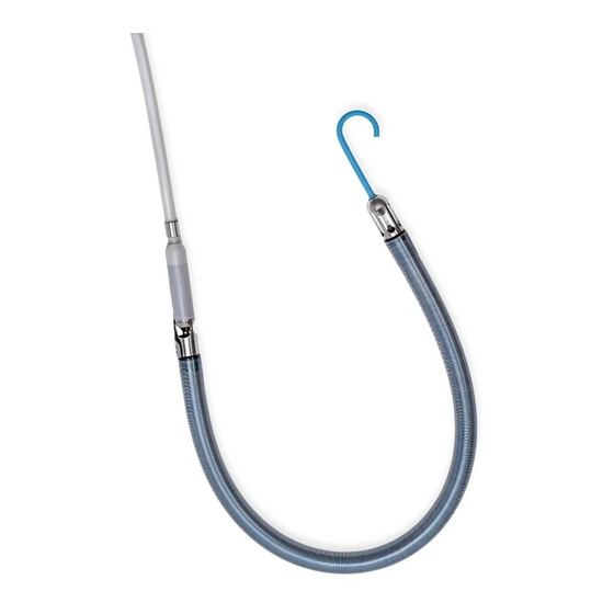
® IMPELLA RP CATHETER The Impella® RP Catheter is an intracardiac microaxial blood pump that delivers up to 4.0 liters of blood per minute from the inferior vena cava into the pulmonary artery. Figure 3.3 illustrates the Impella® RP Catheter. The Impella® RP Catheter has a specially designed three dimensional cannula that is sized to fit through the vessels and hearts of pediatric and adult patients with a Body Surface Area (BSA) equal to or greater than 1.5 m . -
Page 19: Differential Pressure Sensor
Table 3.1 Impella ® RP Catheter Components (continued) Component Description Inlet area The proximal end of the cannula is attached to the inlet area where blood enters the cannula. Motor housing The 21 Fr motor housing consists of an encapsulated motor. Catheter shaft An 11 Fr catheter shaft is located between the motor housing and the blue Impella®... -
Page 20: Automated Impella Controller
The controller weighs 26 lbs (11.8 kg) and can operate on its internal battery for at least 60 minutes when fully charged. Using the controller, the Impella RP System can be used by trained healthcare professionals in healthcare facilities and during medical transport (i.e., ambulance, helicopter, or fixed-winged aircraft) environments. -
Page 21: Purge Cassette
PURGE CASSETTE Do NOT use saline in the purge system. The purge cassette delivers rinsing fluid to the Impella® RP Catheter. The purge fluid (typically 20% dextrose solution) flows from the purge cassette through the catheter to the microaxial blood pump to prevent blood from entering the motor. When the purge cassette is properly installed in the Automated Impella®... -
Page 22: Table 3.2 Purge Cassette Components
Table 3.2 Purge Cassette Components Component Description Purge fluid spike One end spikes the purge fluid bag and the other end connects the bag to the purge cassette supply line Supply line Carries fluid from the purge fluid bag to the purge cassette Contains the components for delivering the purge fluid;... -
Page 23: Accessories
ACCESSORIES Table 3.3 illustrates and describes the accessories used with the Impella® RP Catheter and Automated Impella® Controller. ® ® Table 3.3 Impella RP Catheter and Automated Impella Controller Accessories Component Description The white connector cable connects the Impella® RP Catheter to the Automated Impella® Controller. Clips on the cable are used to secure the purge tubing to the cable. -
Page 24: Figure 3.9 Dextrose Solution
® ® Table 3.3 Impella RP Catheter and Automated Impella Controller Accessories (continued) Component Description Hospital Provided: Dextrose solution (typically 20% dextrose in water with 50 IU/mL of heparin) is used as the purge fluid through the Impella® RP Catheter. Figure 3.9 Dextrose Solution The Automated Impella®... -
Page 25: Using The Automated Impella Controller
4 USING THE AUTOMATED IMPELLA ® CONTROLLER OVERVIEW ....................4.1 AUTOMATED IMPELLA CONTROLLER FEATURES ........4.1 ® AUTOMATED IMPELLA CONTROLLER DISPLAY ......... 4.5 ® PLACEMENT SCREEN ................... 4.8 Placement Signal Waveform................4.8 Motor Current Waveform .................4.9 PURGE SCREEN .....................4.9 Purge Flow ....................4.10 Purge Pressure .................... -
Page 26: Overview
OVERVIEW The Automated Impella Controller is the primary user control interface for the Impella ® ® Catheter. It controls the Impella RP Catheter performance and monitors the catheter for alarms. ® The controller can be powered by AC power or can operate on internal battery power for at least 60 minutes when fully charged. - Page 27 Table 4.1 Automated Impella ® Controller Front View Features Feature Description Display screen Displays user information, including the labels for the soft buttons. Display Options (Display screen elements described in detail later in this section.) Soft buttons Display, open, and close menus. The function for each soft button is defined by If equipped with a VGA labels adjacent to the button on the display screen;...
-
Page 28: Figure 4.2 Automated Impella ® Controller Features - Side Views
Figure 4.2 illustrates the features on the left and right sides of the Automated Impella ® Controller. These features are described in Table 4.2. Bed Mount Purge Cassette Door Release RS-232 Jack USB Connector Ethernet Jack Equipotential Ground Stud AC Fuses Power Switch AC Plug Figure 4.2 Automated Impella... - Page 29 Button located on the left side of the controller; press to open the purge door release cassette door VGA / RS-232 Interface for data transfer by Abiomed maintenance or service personnel; jack if equipped, this interface can also be used for connecting the controller to another monitor to slave the display...
-
Page 30: Automated Impella ® Controller Display
Figure 4.3 and described in Table 4.3. Catheter System Date Serial Number and Time Impella RP S/N: 123456 30 - 06 - 2011 05:30 1. Check purge system tubing for kinks. Purge Flow Low 2. Decrease concentration of dextrose in the purge solution. - Page 31 Table 4.3 Automated Impella ® Controller Display Elements (continued) Display Element Description Mute alarm indicator Displayed in place of the words “MUTE ALARM” when an alarm is silenced. (See section 6 of this manual for more information about the mute alarm function; Figure 6.1 illustrates the mute alarm indicator.) •...
- Page 32 Table 4.3 Automated Impella ® Controller Display Elements (continued) Display Element Description Purge system area Information about the purge system is displayed to the right of the flow area at the bottom of the display screen. Purge system marquee—scrolls from left to right when purge system is operating •...
-
Page 33: Placement Screen
Use the DISPLAY soft button to navigate to the placement screen. 30 - 06 - 2011 05:30 Impella RP S/N: 123456 MUTE ALARM FLOW Placement... -
Page 34: Purge Screen
To the right of the plots, the current purge flow rate and purge pressure are displayed. Use the DISPLAY soft button to navigate to the purge screen. 30 - 06 - 2011 05:30 Impella RP S/N: 123456 MUTE ALARM Purge Flow... -
Page 35: Infusion History
PURGE FLOW The purge flow rate delivered by the purge cassette is displayed in mL/hr. The standard scale for the purge flow (0–30 mL/hr) is displayed to the left of the purge flow plot. The maximum value on this scale can be adjusted from 20 mL/hr to 200 mL/hr in increments of 10 mL/hr. To the right of the plot is a display that labels the plot and shows the most recent value update. -
Page 36: Mobile Operation
Impella RP S/N: 123456 30 - 06 - 2011 16:30 MUTE ALARM FLOW Dextrose Infusion History CONTROL Infusion (mg / hr) Infusion Time Period Volume (ml) Heparin (U) Dextrose (mg) 4000 2000 30 - 06 - 2011 16:00 - 16:30... -
Page 37: Using The Automated Impella Controller With The Impella Rp Catheter
5 USING THE AUTOMATED IMPELLA CONTROLLER ® WITH THE IMPELLA RP CATHETER ® STARTUP .......................5.1 Supplies Needed ....................5.1 Turning on the Automated Impella ® Controller ..........5.2 The Startup Screen ..................5.3 CASE START ....................5.4 Case Start......................5.4 Insert Purge Cassette..................5.5 Connect the Connector Cable ................5.6 Enter Purge Fluid Data ..................5.8 Secure the Purge Tubing ..................5.9 Impella... -
Page 38: Startup
STARTUP Do NOT use an Impella RP System if any part of the system is damaged. ® The sterile components of the Impella ® RP System can be used only if the sterilization indicators show that the contents have been sterilized, the packaging is not damaged, and the expiration date has not elapsed. -
Page 39: Figure 5.1 Automated Impella ® Controller Power Switch
TURNING ON THE AUTOMATED IMPELLA CONTROLLER ® To turn the controller on: Battery Switch Press and hold the power switch on the right side of the Automated Impella Controller ® for 3 seconds (see Figure 5.1). Before operating the Automated Impella ®... -
Page 40: Figure 5.2 Automated Impella ® Controller Startup Screen
THE STARTUP SCREEN The startup screen (see Figure 5.2) appears when you successfully turn on the Automated Check Date and Time Impella Controller. ® The current date and time 30 - 06 - 2011 05:30 Impella 5.0 S/N: 123456 appear at the top of the MUTE startup screen. -
Page 41: Case Start
CASE START Fluoroscopy is required to guide placement of the Impella ® RP Catheter. The small Sensitive Medical Device placement guidewire must be reliably observed at all times. The Impella RP Catheter is a ® The sterile components of the Impella RP System can be used only if the ®... -
Page 42: Figure 5.4 Inserting The Purge Cassette Into The Automated Impella Controller
INSERT PURGE CASSETTE Open the purge cassette package. Disconnect and discard the Y connector. Shaded Steps Pass the purge cassette and spike off the sterile field. All shaded steps require sterile technique. Spike the fluid bag/bottle. Open the purge cassette door by pressing the release on the left side of the controller. Insert the purge cassette into the Automated Impella Controller (as shown in Figure ®... -
Page 43: Figure 5.5 Inserting The Catheter Plug Into The Connector Cable
CONNECT THE CONNECTOR CABLE Remove the Impella RP Catheter from its package using sterile technique and inspect ® the catheter, including its connector, for damage. Remove the white connector cable from its package using sterile technique. Inspect the cable for damage, including damage to the connector pins at the controller end. -
Page 44: Figure 5.7 Priming The Impella Purge Lumen
RP Catheter as shown in ® Error Screens Figure 5.7. If you miss a step in the 30 - 06 - 2011 05:30 Impella RP S/N: 123456 process of setting up the MUTE Impella ® RP Catheter, or if ALARM... -
Page 45: Figure 5.9 Entering Purge Fluid Information
RP Catheter, enter the purge fluid ® information. The screen in Figure 5.9 shows a table of recommended default values for the purge fluid. Impella RP S/N: 123456 30 - 06 - 2011 05:30 MUTE ALARM Catheter is Ready To Insert 1. -
Page 46: Figure 5.10 Connecting The Purge Tubing To The Connector Cable
SECURE THE PURGE TUBING To complete the setup, connect the purge tubing to the white connector cable by pushing the purge tubing into the clips attached to the white connector cable as shown in Figure 5.10. Figure 5.10 Connecting the Purge Tubing to the Connector Cable IMPELLA RP SYSTEM CONFIGURATION ®... -
Page 47: Inserting The Impella Rp Catheter
INSERTING THE IMPELLA RP CATHETER ® NOTE – Proper surgical procedures and techniques are the responsibility of the medical professional. The described procedure is furnished for information purposes only. Each physician must evaluate the appropriateness of the procedure based on his or her medical training and experience, the type of procedure, and the type of systems used. - Page 48 Wet the cannula with sterile water and backload the catheter onto the placement guidewire. One or two people can load the catheter on the guidewire. Advance the guidewire into the Impella RP Catheter and stabilize the cannula ® between the fingers. This prevents pinching of the outlet area. The guidewire must Use Fluoroscopy for exit the inlet area on the inner radius of the cannula and align with the straight Placement...
-
Page 49: Positioning And Starting The Impella ® Rp Catheter
The catheter inlet area should be in the inferior vena cava and the outlet area in the pulmonary artery. Verify placement with fluoroscopy. 30 - 06 - 2011 05:30 Impella RP S/N: 123456 MUTE ALARM Placement... -
Page 50: Use Of The Repositioning Sheath And The 23 Fr Peel-Away Introducer
USE OF THE REPOSITIONING SHEATH AND THE 23 FR PEEL-AWAY INTRODUCER Flush the sidearm of the repositioning sheath located on the catheter shaft. Attach a stopcock and flush the repositioning sheath prior to advancing the sheath. Apply manual pressure above the puncture site and remove the 23 Fr peel-away introducer completely from the vein over the catheter shaft. -
Page 51: Performance Levels
If suction is an issue, the flow displayed on the controller may be higher than the actual Impella RP flow rate. If the suction alarm appears on the controller when the Impella RP is running at P-levels between P7 and P9, decrease P-level to P6, or to P5 or P4, as needed, to resolve suction. -
Page 52: Purge Cassette Procedures
PURGE CASSETTE PROCEDURES When replacing the purge cassette, the replacement process must be completed Replacement Time within 2 minutes. The Impella RP Catheter may be damaged if replacement takes ® longer than 2 minutes. If the purge flow is more than 7 mL/hr or the dextrose There are four procedures for maintaining the Impella ®... -
Page 53: Change Purge Fluid
Insert the new purge cassette into the controller. Be sure to slide the purge pressure transmitter into place and extend the purge tubing through the gap in the purge cassette door when you close the door. The system automatically primes the purge cassette. A progress bar shows the progress of the priming. -
Page 54: Change Purge Cassette
If you are proceeding to flush the purge fluid from the cassette, select OK to deliver a bolus to the system. A progress bar shows the progress of the bolus. After the bolus is delivered, the controller automatically proceeds to the next screen. RP Catheter and select OK to flush the purge Disconnect the luer from the Impella ®... -
Page 55: Troubleshooting The Purge System
TROUBLESHOOTING THE PURGE SYSTEM LOW PURGE PRESSURE If at any time during the course of support with the Impella RP Catheter, ® the Automated Impella Controller alarms “Purge Pressure Low,” follow the ® instructions below. Purge Pressure Optimal purge pressure is Inspect the purge system for leaks. -
Page 56: Purge System Open
PURGE SYSTEM OPEN If at any time during the course of support with the Impella RP Catheter, ® the Automated Impella Controller alarms “Purge System Open,” follow the ® instructions below. Purge System Open Alarm Inspect the purge system for leaks. This alarm may occur if purge If no leaks are visible, there may be a problem with the purge cassette. -
Page 57: Patient Weaning
PATIENT WEANING Weaning the patient from the Impella ® RP Catheter is at the discretion of the physician. Weaning may occur when right ventricular recovery is suspected and/or the patient is approaching the maximum duration of use for the Impella RP Catheter. -
Page 58: Clinical Experience
6 CLINICAL EXPERIENCE PIVOTAL CLINICAL STUDY DESIGN – RECOVER RIGHT ......6.1 Inclusion and Exclusion Criteria ................6.1 Study Organization …………………..............6.2 Statistical Considerations ……………..............6.3 ACCOUNTABILITY OF COHORT ……………..........6.3 Study Population Demographics and Baseline Characteristics ..... 6.4 Procedural, Support and Hemodynamic Characteristics ……....... 6.5 Primary Endpoint Results ………….............. -
Page 59: Pivotal Clinical Study Design - Recover Right
RECOVER RIGHT was a prospective, multi-center, non-randomized study. The primary objective for the study was to assess safety and effectiveness of the use of the Impella RP device in patients with RVF refractory to medical treatment who require hemodynamic support. The intent of therapy was to restore normal right heart hemodynamics, reduce right ventricular work, and allow the right heart time to potentially recover adequate contractile function or to be bridged to the next therapy. - Page 60 2. End organ failure (defined as hepatic total bilirubin ≥ 5 mg/dL based on lab data within 24 hours prior to Impella RP initiation, renal: creatinine ≥ 4 mg/dL based on lab data within the 24 hours prior to Impella RP initiation) 3.
-
Page 61: Accountability Of Cohort
STUDY ORGANIZATION ABIOMED was responsible for site management, site monitoring, data management and oversight of safety processes. The study also included an independent Echocardiography Core Laboratory (Duke Clinical Research Institute, Durham, NC) that provided imaging protocol design, site training/certification and image management/analyses. A cardiothoracic surgeon, selected as the Physician Medical Monitor, was charged with reviewing study data in order to protect the safety and well-being of human subjects and the scientific integrity of the investigation. -
Page 62: Study Population Demographics And Baseline Characteristics
STUDY POPULATION DEMOGRAPHICS AND BASELINE CHARACTERISTICS The patient baseline characteristics are summarized in Table 6.1. The overall age was 59±15 years old. Among all patients, 88.5% presented with congestive heart failure (CHF), 60% had history of arrhythmia, 57% had ICD or pacemaker implanted, 53% had diabetes, 37.5% had chronic kidney disease, and 20% had prior CVA. -
Page 63: Procedural, Support And Hemodynamic Characteristics
25 mL of blood loss recorded in 89.3% and 60.7% patients, respectively. The average duration of support with the Impella RP was 3.05±1.5 days for the entire population (ranging Impella ® RP with the Automated Impella ® Controller... - Page 64 from 13 hours to 8 days) and was similar between the two cohorts. The pump flow on support was 3.23±0.35 L (ranging 2.5-4.00 L/min). Table 6.3 Procedural characteristics All Patients Cohort A Cohort B Procedural Characteristics (N=30) (N=18) (N=12) Side of Implantation Left Femoral Vein 3.3% (1/30) 0.0% (0/18)
-
Page 65: Primary Endpoint Results
(3/18 in Cohort B, 1/3 at access site). Overall, the amount of bleeding during insertion of the device was also low (93% of the patients lost less than 100 mL of blood for the combined introducer sheath placement and the Impella RP catheter insertion. SECONDARY EFFECTIVENESS ENDPOINT RESULTS... -
Page 66: Figure 6.3 Lvad Flow Changes From Baseline To On-Support
Figure 6.2 Cardiac index (CI) and central venous pressure (CVP) measured during the study Improvement in LVAD flow or LV pumping function The LVAD flow in Cohort A patients improved after the initiation of Impella RP from 3.96±0.16 L/min to 4.62±0.14 L/min, as depicted in Figure 6.3. -
Page 67: Figure 6.4 Use Of Inotropes During Impella Rp Support
The majority of these patients showed global (versus regional) dysfunction prior to use of the Impella RP device. In 90% of the patients (19/21), there was either an improvement or maintenance of right ventricular function post device placement, as shown in Figure 6.5. -
Page 68: Figure 6.5 Right Ventricular Function Changes
During the RECOVER RIGHT trial, the clinical investigators reported seven (7) device malfunctions in 7 different patients: 5 were related to the Impella RP pump, one to the AIC and one to the off the shelf introducer sheath. Only one affected patient had a device related AE, which was related to the initial insertion of the Impella RP pump, which ultimately was successfully delivered for support. - Page 69 73% at 30 days or discharge (whichever is longer) or to a long term therapy. The Impella RP device had a reasonable overall safety profile, with reliable percutaneous insertion and a low incidence of bleeding and vascular complications.
-
Page 70: Automated Impella Controller Alarms
7 AUTOMATED IMPELLA® CONTROLLER ALARMS ALARMS OVERVIEW ................... 7.1 Alarm Levels ...................... 7.1 Alarm Display ....................7.2 Mute Alarm Function ..................7.2 ALARM MESSAGE SUMMARY ..............7.3... -
Page 71: Alarms Overview
ALARMS OVERVIEW The Automated Impella® Controller monitors various functions to determine whether specific operational parameters are within expected limits. When a parameter goes outside of its specified limits, the Automated Impella® Controller sounds an alarm tone and displays an alarm message that can be viewed on the display screen on the front of the controller. -
Page 72: Figure 7.1 Alarm Window
Controller is powered down or after a power failure. The controller does, however, maintain a long-term log that is saved after the Automated Impella® Controller is powered down or after a power failure and this information may be downloaded by Abiomed personnel. Instructions for Use & Clinical Reference Manual (US) -
Page 73: Alarm Message Summary
ALARM MESSAGE SUMMARY Table 7.2 briefly describes all of the alarm messages that may appear on the Automated Impella® Controller when used with the Impella® RP Catheter. ® Table 7.2 Automated Impella Controller Alarm Messages Severity Alarm Header Action Cause Impella Stopped 1. - Page 74 Table 7.2 Automated Impella ® Controller Alarm Messages (continued) Severity Alarm Header Action Cause Purge System Failure 1. Replace purge cassette. There is a problem with the purger unit driver. 2. Switch to backup controller. Impella Stopped Restart Impella, or Impella®...
- Page 75 Table 7.2 Automated Impella ® Controller Alarm Messages (continued) Severity Alarm Header Action Cause Complete Procedure 1. Follow the steps on the screen or User has not responded to a de-air or purge procedure screen for 2. Exit the procedure more than 1 minute or a transfer to standard configuration screen for more than 5 minutes.
- Page 76 Sensor Failure, Purge Flow Low, or <Alarm will be listed here> Purge System Blocked alarm. Controller is running on battery power. AC Power Disconnected AC power was disconnected. Contact Abiomed Service to update Purge Cassette Incompatible purge cassette RFID Impella Controller. Incompatible version.
-
Page 77: General System Information
ALARM DELAY INFORMATION ..............8.12 PATIENT ENVIRONMENT ................8.12 WHITE CONNECTOR CABLE ................8.13 IMPELLA ® RP CATHETER PARAMETERS ............8.13 CLEANING ....................8.14 STORING THE AUTOMATED IMPELLA ® CONTROLLER ........8.14 RETURNING AN IMPELLA ® RP CATHETER TO ABIOMED (UNITED STATES) .................... 8.14... -
Page 78: Terminology, Abbreviations, And Symbols
TERMINOLOGY, ABBREVIATIONS, AND SYMBOLS TERMINOLOGY AND ABBREVIATIONS Identification number of the Impella® RP Catheter; stated Catheter serial number on the package label, on the blue Impella® plug, and the Automated Impella® Controller display screen The terms “dextrose” and “glucose” are used Dextrose and Glucose interchangeably to refer to the solution used as purge fluid for the Impella®... - Page 79 REF 123456 Abiomed part number (eg, part number 123456) SN 123456 Manufacturer’s serial number (eg, serial number 123456) Non Sterile! The product is not sterile Use-by date (eg, use before June 1, 2016) 2016-06-01 Do not reuse Sterilized using ethylene oxide Electric scrap;...
-
Page 80: Automated Impella® Controller Mechanical Specifications
Weight – Packaged Maximum: 13.6 kg (30 lbs) Maintenance and 12 months repair interval (Work must be performed by technicians authorized by Abiomed) AUTOMATED IMPELLA® CONTROLLER ELECTRICAL SPECIFICATIONS AC operation 100-230 V AC (nominal); 47-63 Hz; 1.1 A Internal battery operation 14.4 V DC (nominal);... -
Page 81: Equipment Design
EQUIPMENT DESIGN The Automated Impella® Controller conforms to the applicable requirements of the following standards: • IEC 60601-1 (2005/01/01) Ed:3 Medical Electrical Equipment Part 1: General Requirements for Basic Safety and Essential Performance • CSA C22.2#60601-1 (2008) Ed:3 Medical Electrical Equipment Part 1: General Requirements for Basic Safety and Essential Performance •... -
Page 82: Equipment Classifications
This device may not cause harmful interference. This device must accept any interference received, including interference that may cause undesired operation. Changes or modifications not expressly approved by Abiomed, Inc. could void the user’s authority to operate this device. ®... -
Page 83: Electromagnetic Compatibility
If adjacent or stacked use is necessary, the equipment or system should be observed to verify normal operation in the configuration in which it will be used. Use of cables, other than those sold by Abiomed, may result in increased emissions or decreased immunity of the Automated Impella® Controller. - Page 84 TABLE 202 Guidance and Manufacturer’s Declaration – Immunity The Automated Impella® Controller is intended for use in the electromagnetic environment specified below. The customer or user of the Automated Impella® Controller should ensure that it is used in such an environment. Electromagnetic IEC 60601 Compliance...
- Page 85 TABLE 203 Guidance and Manufacturer’s Declaration – Emissions, Equipment and Systems that are Life-Supporting The Automated Impella® Controller is intended for use in the electromagnetic environment specified below. The customer or user of the Automated Impella® Controller should ensure that it is used in such an environment.
- Page 86 TABLE 205 Recommended Separation Distances Between Portable and Mobile ® RF Communications Equipment and the Automated Impella Controller, Equipment and Systems that are Life-Supporting The Automated Impella® Controller is intended for use in the electromagnetic environment in which radiated disturbances are controlled. The customer or user of the Automated Impella® Controller can help prevent electromagnetic interference by maintaining a minimum distance between portable and mobile RF communications equipment and the Automated Impella®...
-
Page 87: Transport Between Hospitals
AC power inverter. IMPORTANT TRANSPORT CONSIDERATIONS 1. Planning is critical to success. Abiomed representatives can help with planning for transport. They can be contacted 24 hours a day at 1-800-422-8666. 2. The Automated Impella® Controller should be fully charged prior to transport. Keep the Automated Impella®... -
Page 88: Transport Within The Hospital
RTCA/DO-160G section 21.4 and has not been tested for radiated emissions per RTCA/DO-160G section 21.5. Abiomed recommends that air transport carriers follow the guidance FAA Advisory Circular AC No: 91-21.1B. Section 8-a of FAA Advisory Circular AC No: 91-21.1B states:... -
Page 89: Alarm Delay Information
ALARM DELAY INFORMATION ® For some Automated Impella Controller alarms, there is a short delay between the triggered event and the audible annunciation and visual display of the alarm. Impella Defective 8 second delay Controller Error 12±3 second delay Emergency Shutdown Imminent 15±1 second delay Battery Failure 28±8 second delay... -
Page 90: White Connector Cable
WHITE CONNECTOR CABLE Length 2.5 m Service life Single use only IMPELLA® RP CATHETER PARAMETERS Speed range 0 to 33,000 rpm Power consumption Less than 23 W Voltage Max. 20 V DC Flow-Maximum 4.0 L/min Purging the Impella® RP Catheter Recommended purge fluid 20% dextrose solution with heparin concentration of 50 IU per mL... -
Page 91: Cleaning
RETURNING AN IMPELLA® RP CATHETER TO ABIOMED (UNITED STATES) ® To return an Impella RP Catheter to Abiomed, contact your local Clinical Consultant for an ® Abiomed-approved return kit.* The kit includes instructions for returning the Impella Catheter to Abiomed. -
Page 92: Appendices
APPENDICES APPENDIX A: AUTOMATED IMPELLA CONTROLLER MENU STRUCTURE .. A.1 ® Overview ......................A.1 MUTE ALARM ....................A.1 FLOW CONTROL ....................A.1 DISPLAY ......................A.2 PURGE SYSTEM ....................A.2 MENU ......................A.3... -
Page 93: Appendix A: Automated Impella Controller Menu Structure
APPENDIX A: AUTOMATED IMPELLA CONTROLLER ® MENU STRUCTURE OVERVIEW The soft buttons on the Automated Impella Controller provide access to the controller menu ® structure. The menu structure has 5 main elements: • MUTE ALARM • FLOW CONTROL • DISPLAY •... - Page 94 DISPLAY The DISPLAY soft button opens a menu that includes the following options for viewing waveforms and navigating to other screen displays: • Y-axis Scale—opens a menu from which you can select a waveform and change its appearance by adjusting the scale of the y-axis. Once the waveform is selected, turn the selector knob clockwise to increase the y-axis scale and counterclockwise to decrease the y-axis scale.
- Page 95 MENU The MENU soft button opens a menu of options related to controller settings, alarm history, repositioning, offset adjustment, and starting a procedure. The menu includes the following options: • Settings / Service Service System Information. Opens the System Information table. This provides information about the software version, IP addresses, current type of Impella Catheter, and current catheter runtime.
- Page 96 INDEX TO BE DEVELOPED...
- Page 97 Clinical support 24 hours per day, 7 days a week: 1-800-422-8666 (US) +49 (0) 1805 2246633 (EU) www.abiomed.com Abiomed, Inc. Abiomed Europe GmbH 22 Cherry Hill Drive Neuenhofer Weg 3 Danvers, Massachusetts 01923 USA 52074 Aachen, Germany Voice: 978-777-5410 Voice: +49 (241) 8860-0...
Need help?
Do you have a question about the Impella RP and is the answer not in the manual?
Questions and answers