
Related Manuals for Abiomed Impella 2.5


Summary of Contents for Abiomed Impella 2.5
- Page 1 Ventricular Impella Support Systems for Use During Cardiogenic Shock Impella 2.5, 5.0, LD and Impella CP ® ® INSTRUCTIONS FOR USE & CLINICAL REFERENCE MANUAL (United States only)
- Page 2 The ABIOMED logo and ABIOMED are registered trademarks of Abiomed, Inc. in the U.S.A. and certain foreign countries. Recovering hearts. Saving lives. is a trademark of Abiomed, Inc. Impella is a registered trademark of Abiomed Europe GmbH, a wholly owned subsidiary of Abiomed, Inc., in the U.S.A. and certain foreign countries.
-
Page 3: Instructions For Use
Rx Only Abiomed, Inc. 22 Cherry Hill Drive Danvers, MA 01923 978-777-5410 (voice) 978-777-8411 (fax) clinical@abiomed.com (email) Abiomed Europe GmbH Neuenhofer Weg 3 52074 Aachen, Germany +49 (241) 8860-0 (voice) +49 (241) 8860-111 (fax) europe@abiomed.com (email) www.abiomed.com 24-Hour Clinical Support Center: N. -
Page 5: Table Of Contents
LD Catheter ............5.52 Storing the Automated Impella ® Controller ..........9.16 Returning an Impella Catheter to Abiomed (United States) ..... 9.16 ® 6 CLINICAL EXPERIENCE Cardiac Shock After Myocardial Infarction ..........6.1 APPENDICES Summary of Primary Clinical Studies ............6.1 Appendix A: Impella ®... - Page 6 TABLE OF CONTENTS FIGURES Figure 5.21 Inserting the Diagnostic Catheter ..........5.18 Figure 3.1 Impella ® Catheter in the Heart ..........3.1 Figure 5.22 Loading the Catheter on the Guidewire using the Figure 3.2a Set-up Configuration of the Automated Impella ®...
- Page 7 Figure 6.23 Kaplan-Meier Curve for 30 Day Survival Using Classification A Table 5.3 P-level Flow Rates for the Impella 2.5 Catheter ...... 5.34 ® (Patients with Impella 2.5) ............6.26 Table 5.4 P-level Flow Rates for the Impella CP Catheter ....... 5.34 ®...
-
Page 9: Introduction
Controller, and instructions on cleaning and storing system components as well ® as returning components to Abiomed. • Appendices at the end of the manual provide supplemental information about topics including the Impella Limited Service Warranty; Abiomed-approved guidewires and ® introducers; and the Automated Impella Controller menu structure. ®... -
Page 11: Indications, Contraindications, And Potential Adverse Events
1 INDICATIONS, CONTRAINDICATIONS, AND POTENTIAL ADVERSE EVENTS INDICATIONS (UNITED STATES) ..............1.1 Impella ® 2.5, Impella CP ® , Impella ® 5.0, and Impella ® LD ........ 1.1 CONTRAINDICATIONS (UNITED STATES)............1.1 POTENTIAL ADVERSE EVENTS (UNITED STATES) .........1.2... -
Page 13: Indications (United States)
INDICATIONS (UNITED STATES) IMPELLA 2.5, IMPELLA CP , IMPELLA 5.0, AND IMPELLA ® ® ® ® The Impella 2.5, Impella CP , Impella 5.0, and Impella LD Catheters, in conjunction with ® ® ® ® the Automated Impella ® Controller, are temporary ventricular support devices intended for short term use (<... -
Page 14: Potential Adverse Events (United States)
POTENTIAL ADVERSE EVENTS (UNITED STATES) • Acute renal dysfunction • Myocardial infarction • Aortic insufficiency • Need for cardiac, thoracic or abdominal operation • Aortic valve injury • Perforation • Atrial fibrillation • Renal failure • Bleeding • Repeat revascularization •... -
Page 15: Warnings And Cautions
2 WARNINGS AND CAUTIONS WARNINGS ....................2.1 CAUTIONS ....................2.3... -
Page 17: Warnings
® be preceded by the completion of a contemporary Abiomed Impella training ® program and include on-site proctoring during the first use by Abiomed clinical Warnings alert you to support personnel certified in the use of Impella ® situations that can cause death or serious injury. - Page 18 If adjacent or stacked use is necessary, the equipment or system should be observed to verify normal operation in the configuration in which it will be used. Use of cables, other than those sold by Abiomed, may result in increased emissions or decreased immunity of the Automated Impella Controller.
-
Page 19: Cautions
Use only original accessories and replacement parts supplied by Abiomed. Do NOT use damaged or contaminated connector cables. To prevent device failure, do NOT start the Impella ®... - Page 20 Minimize exposure of Impella System components to sources of electromagnetic ® interference (EMI). Exposure to sources of EMI, such as cell phones and two-way radios, may cause operational interference. To clear interference, either increase the distance between system components and the EMI source or turn off the EMI source. During use with the Remote Link, a Medical Device Data System (MDDS), if the Automated Impella Controller is exposed to strong electromagnetic disturbances,...
-
Page 21: The Impella ® Catheter And Automated Impella ® Controller
3 THE IMPELLA CATHETER AND ® AUTOMATED IMPELLA CONTROLLER ® OVERVIEW ....................3.1 Reusable System Components ................. 3.1 Single-use System Components ...............3.2 Impella Set-up and Insertion kits (Impella 2.5 and Impella CP ) ....3.2 ® ® ® Impella Axillary Insertion kit (Impella 2.5, 5.0 and Impella CP ) ....3.2 ®... -
Page 23: Overview
OVERVIEW The Impella Catheter is an intravascular microaxial blood pump that supports a patient’s ® circulatory system during cardiogenic shock, low output syndrome, or other conditions. The Impella 2.5, 5.0, and Impella CP Catheters can be inserted percutaneously through the ®... -
Page 24: Impella Cp ® Catheter, And Accessories
SINGLE-USE SYSTEM COMPONENTS The Impella System also includes the following single-use components: ® • Impella Catheter ® • Purge cassette • Introducer kit (Impella 2.5 and Impella CP ® ® • 0.018 inch, 260 cm placement guidewire (Impella 2.5, 5.0, and Impella CP ®... - Page 25 SYSTEM CONFIGURATIONS Initial set-up configuration for Impella 2.5 and Impella CP ® ® Figure 3.2a illustrates how the Automated Impella Controller connects to the Impella 2.5 or ® ® Impella CP ® Catheter and accessory components in the initial set-up configuration. Dextrose Solution Automated Impella...
-
Page 26: Figure 3.3 Set-Up Configuration Of The Automated Impella ® Controller, Impella
System configuration for Impella 5.0 and LD ® Figure 3.3 illustrates how the Automated Impella Controller connects to the Impella 5.0 or LD ® ® Catheter and accessory components in the initial set-up configuration. Disconnect Y Connector from Purge Tubing Disconnect Y Connector from Purge Tubing Dextrose Solution... -
Page 27: Impella ® Catheter
IMPELLA CATHETER ® The Impella Catheter is an intravascular microaxial blood pump that delivers up to 2.5 liters ® (Impella 2.5), 3.3 liters (Impella CP ) or 5.0 liters (Impella 5.0 and LD) of blood per minute ® ® ® from the left ventricle into the aorta. - Page 28 Pressure Infusion Reservoir Red Impella ® Plug Filter Check Valve Clear Sidearm Catheter Shaft Pigtail Inlet Area Repositioning Unit Cannula Impella ® Differential Pressure Sensor Motor Outlet Housing Area Check Valve Infusion Red Impella ® Filter Plug Pressure Inlet Area Clear Sidearm Reservoir Cannula...
-
Page 29: Table 3.3 Impella ® Catheter Components
Table 3.3 Impella ® Catheter Components Component Description Pigtail The 6 Fr pigtail is attached to the cannula at the distal end of the inlet area. It assists with stabilizing the Impella 2.5, 5.0, and Impella CP ® ® Catheters in the correct position in the left ventricle. Inlet area The inlet area, located at the distal tip of the cannula, has four openings (windows) (five for the Impella... - Page 30 Table 3.3 Impella ® Catheter Components (continued) Component Description Repositioning unit The repositioning unit on the Impella 2.5, 5.0, and Impella CP ® ® Catheters consists of a sheath, an anticontamination sleeve with an anchoring ring, and suture pads. • The sheath (with hemostatic valve) is graduated from 9 Fr to 15 Fr.
-
Page 31: And Ld Differential Pressure Sensor (Impella ® 5.0 Shown)
The pressure sensor is a flexible membrane integrated into the cannula (see Figure 3.5). One side of the sensor is exposed to the blood pressure on the outside of the cannula and the other side is exposed to the pressure of the blood inside of the cannula. The sensor generates an electrical signal proportional to the difference between the pressure outside the cannula and the pressure inside. -
Page 32: Placement Signal
When the Impella 5.0 or LD Catheter is correctly positioned across the aortic valve, the changes ® in pressure associated with the cardiac cycle result in a pulsatile placement signal (see Figure 3.7). During diastole (time zero in Figure 3.6), the large pressure difference between the aorta and the left ventricle creates a large electrical signal. -
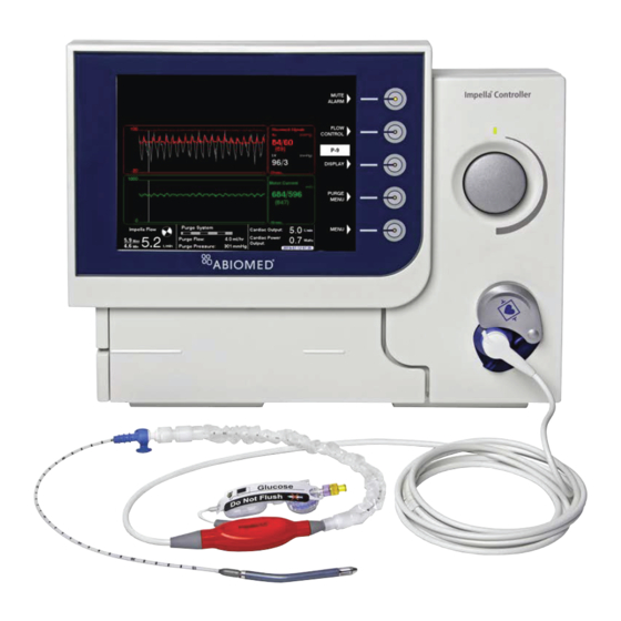
Page 33: Automated Impella ® Controller
AUTOMATED IMPELLA CONTROLLER ® The Automated Impella Controller (see Figure 3.9) provides three vital functions to the ® Automated Impella ® operation of the Impella Catheter: ® Controller Battery Power • The controller provides an interface for monitoring and controlling the function of the Impella ®... -
Page 34: Purge Cassette
When the purge cassette is properly installed in the Automated Impella Controller, the Abiomed logo is upright and facing you. Figure 3.10 ® illustrates the purge cassette and related components. Table 3.4 describes each component. -
Page 35: Table 3.4 Purge Cassette Components
Table 3.4 Purge Cassette Components Component Description Purge fluid spike One end spikes the purge fluid bag and the other end connects the bag to the purge cassette supply line Supply line Carries fluid from the purge fluid bag to the purge cassette Purge cassette Contains the components for delivering the purge fluid;... -
Page 36: Accessories
ACCESSORIES Table 3.5 illustrates and describes the accessories used with the Impella Catheter and ® Automated Impella Controller. ® Table 3.5 Impella Catheter and Automated Impella Controller Accessories ® ® Component Description The white connector cable connects the Impella ® Catheter to the Automated Impella Controller. -
Page 37: Figure 3.15 Impella ® Axillary Insertion Kit (Impella ® 2.5, 5.0, And Impella Cp ® )
Impella CP ® It is important to use only the guidewire supplied with The 0.018 inch, 260 cm placement guidewire is the system or an Abiomed- used for the placement of the Impella 2.5, 5.0, ® approved alternative. or Impella CP Catheter. -
Page 39: Using The Automated Impella ® Controller
4 USING THE AUTOMATED IMPELLA ® CONTROLLER OVERVIEW ....................4.1 AUTOMATED IMPELLA CONTROLLER FEATURES ........4.2 ® HOME SCREEN ....................4.6 PLACEMENT SCREEN ..................4.9 Placement Signal Waveform................4.9 Motor Current Waveform ................4.10 PURGE SCREEN ...................4.10 Purge Flow ....................4.11 Purge Pressure ....................4.11 INFUSION HISTORY SCREEN ............... -
Page 41: Overview
OVERVIEW The Automated Impella Controller is the primary user control interface for the Impella ® ® Catheter. It controls the Impella Catheter performance, monitors the catheter for alarms, and ® provides real-time catheter position information regarding the location of the catheter across the aortic valve. -
Page 42: Automated Impella ® Controller Features
AUTOMATED IMPELLA CONTROLLER FEATURES ® IMPORTANT NOTE: The underside of the Automated Impella Controller has a battery switch to turn on the batteries. ® This switch is turned off for shipping purposes. Before operating the Automated Impella Controller for the first time, ®... - Page 43 Table 4.1 Automated Impella ® Controller Front View Features Feature Description Display Options Display screen Displays user information, including the labels for the soft buttons. (Display screen elements described in detail later in this section.) If equipped with a VGA Soft buttons Display, open, and close menus.
-
Page 44: Figure 4.2 Automated Impella ® Controller Features - Side Views
Figure 4.2 illustrates the features on the left and right sides of the Automated Impella ® Controller. These features are described in Table 4.2. Bed Mount Purge Cassette Door Release VGA OUT USB Connector Service Ethernet Jack Equipotential Ground Stud AC Fuses Power Switch AC Plug... - Page 45 VGA OUT Connection for connecting the controller to another monitor to slave the display USB connector Interface for data transfer by Abiomed maintenance or service personnel Service Connection used by Abiomed maintenance or service personnel AC fuses Electrical safety device in the event of current overload...
-
Page 46: Home Screen
HOME SCREEN The home screen displays operating parameters and information for the entire Impella System. ® Figure 4.3 illustrates the home screen. Each element of the display is described in Table 4.3. Catheter System Date Serial Number and Time 30 - 09 - 2012 05:30 Impella CP S/N: 123456 1 . - Page 47 Table 4.3 Automated Impella ® Controller Display Elements (continued) Display Element Description Mute alarm indicator Displayed in place of the words “MUTE ALARM” when an alarm is silenced. (See section 8 of this manual for more information about the mute alarm function;...
- Page 48 Table 4.3 Automated Impella ® Controller Display Elements (continued) Display Element Description Purge system area Y connector icon (for Impella 2.5 and Impella CP ® ® (continued) • Appears above the purge system marquee when the Impella ® System is configured using the Y connector in the set-up configuration Purge flow •...
-
Page 49: Placement Screen
PLACEMENT SCREEN The placement screen (see Figure 4.4) displays real-time operating data for the system. The screen displays the placement signal and motor current waveforms as well as the maximum/ minimum and average values for each waveform in the central display area of the screen. Use the DISPLAY soft button to navigate to the placement screen. -
Page 50: Purge Screen
MOTOR CURRENT WAVEFORM Motor current is a measure of the energy intake of the Impella Catheter motor. The energy intake ® varies with motor speed and the pressure difference between the inlet and outlet areas of the cannula. Motor current (see Figure 4.4) provides information about the catheter position relative to the aortic valve. -
Page 51: Infusion History Screen
PURGE FLOW Purge Flow The purge flow rate delivered by the purge cassette is displayed in mL/hr. The standard scale for the purge flow (0–30 mL/hr) is displayed to the left of the purge flow plot. The maximum value In the initial set-up on this scale can be adjusted from 20 mL/hr to 200 mL/hr in increments of 10 mL/hr. -
Page 52: Mobile Operation
Impella CP S/N: 123456 30 - 09 - 2012 16:30 MUTE ALARM FLOW Dextrose Inf usion History CONTROL Inf usion ( mg / hr) 0 . 0 A U T O 0 . 0 Inf usion Time Period V olume ( ml) Heparin ( U) Dextrose ( mg) 4000... -
Page 53: Using The Automated Impella ® Controller With The Impella ® Catheter
5 USING THE AUTOMATED IMPELLA CONTROLLER ® WITH THE IMPELLA CATHETER ® PRE-SUPPORT EVALUATION .................5.1 Alternative Sheaths and Surgical Techniques ............ 5.1 STARTUP .......................5.2 Supplies Needed ....................5.2 Turning On the Automated Impella ® Controller ..........5.3 The Startup Screen ..................5.4 CASE START ....................5.5 Case Start......................5.5 Insert Purge Cassette..................5.6 Connect the Impella... - Page 54 Using the Automated Impella Controller ® With the Impella Catheter (continued) ® POSITIONING AND STARTING THE IMPELLA 5.0 CATHETER ....5.38 ® POSITIONING AND STARTING THE IMPELLA LD CATHETER.....5.41 ® PURGE CASSETTE PROCEDURES ............... 5.44 Change Purge System ..................5.45 Change Purge Fluid ..................5.46 Change Purge Cassette .................5.47 De-Air Purge System ..................5.47 TROUBLESHOOTING THE PURGE SYSTEM ..........
-
Page 55: Pre-Support Evaluation
PRE-SUPPORT EVALUATION Before initiating the procedure, evaluate the patient for factors that may prevent successful placement of the Impella Catheter. Use imaging technology to examine the patient’s ® vasculature and femoral access site. An echo assessment of the left ventricle is also recommended to rule out left ventricular thrombus, mechanical aortic valves, or severe aortic insufficiency. -
Page 56: Startup
STARTUP Do NOT use an Impella System if any part of the system is damaged. ® The sterile components of the Impella System can be used only if the sterilization ® indicators show that the contents have been sterilized, the packaging is not damaged, and the expiration date has not elapsed. -
Page 57: Figure 5.1 Automated Impella Controller Power Switch
Hemashield Platinum graft, number 2 sutures or umbilical tape, 4 Fr–6 Fr pigtail or diagnostic catheter of choice to achieve an apical wire placement while avoiding a subannular wire position, diagnostic 0.035 inch guidewire, and Abiomed 0.018 inch placement guidewire... -
Page 58: Figure 5.2 Automated Impella ® Controller Startup Screen
THE STARTUP SCREEN The startup screen (see Figure 5.2) appears when you successfully turn on the Automated Check Date and Time Impella Controller. ® The current date and time 30 - 06 - 2011 05:30 appear at the top of the MUTE startup screen. -
Page 59: Case Start
CASE START Fluoroscopy is required to guide placement of the Impella Catheter and, for the ® Sensitive Medical Device Impella CP , during rewire through the guidewire access port. The small placement ® guidewire must be reliably observed at all times. The Impella Catheter is a ®... -
Page 60: Figure 5.4 Inserting Purge Cassette Into Automated Impella ® Controller
INSERT PURGE CASSETTE Shaded Steps Open the purge cassette package. Open the purge cassette package. All shaded steps require Secure the red and yellow luers to the sterile field (Impella Secure the red and yellow luers to the sterile field (Impella 2.5 and Impella CP 2.5 and Impella CP ) or... -
Page 61: Figure 5.5 Inserting The Catheter Plug Into The Connector Cable
CONNECT THE IMPELLA CATHETER ® Remove the Impella Remove the Impella Catheter from its package using sterile technique and inspect the Catheter from its package using sterile technique and inspect the ® ® catheter, including its connector, for damage. catheter, including its connector, for damage. Remove the white connector cable from its package using sterile technique. -
Page 62: Figure 5.7 Priming The Impella Purge Lumen
Impella Catheter. (See Figure ® 5.7) Error Screens If you miss a step in the Impella 2.5 S/N: 123456 30 - 06 - 2011 05:30 process of setting up the MUTE Impella ®... -
Page 63: Figure 5.9 Priming The Placement Signal Lumen
PRIMING THE PLACEMENT SIGNAL LUMEN (IMPELLA 2.5 AND ® IMPELLA CP ® 30 - 06 - 2011 05:30 Impella 2.5 S/N: 123456 MUTE ALARM Prime Placement Signal Lumen 1. Sq ueez e white f lush v alv e until controller b eeps. EX IT... -
Page 64: Figure 5.11 Entering Purge Fluid Information
ENTER PURGE FLUID DATA After confirming that fluid is exiting the Impella Catheter, enter the purge fluid ® information. The screen in Figure 5.11 shows a table of recommended default values for the purge fluid. 30 - 09 - 2012 05:30 Impella CP S/N: 123456 MUTE ALARM... -
Page 65: Figure 5.12 Connecting The Purge Tubing To The Connector Cable
SECURE THE PURGE TUBING To complete the setup, connect the purge tubing to the white connector cable by pushing the purge tubing into the clips attached to the white connector cable as shown in Figure 5.12. Figure 5.12 Connecting the Purge Tubing to the Connector Cable IMPELLA SYSTEM SET-UP CONFIGURATION ®... -
Page 66: Impella ® 2.5 Catheter Insertion (Wired)
IMPELLA 2.5 CATHETER INSERTION (WIRED) ® Use Fluoroscopy for Placement NOTE – Proper surgical procedures and techniques are the responsibility of the medical professional. The described procedure is furnished for information purposes only. Each Impella ® Catheter physician must evaluate the appropriateness of the procedure based on his or her performance will be medical training and experience, the type of procedure, and the type of systems used. -
Page 67: Figure 5.15 Inserting The Diagnostic Catheter
Insert a diagnostic catheter (Abiomed recommends a 6 Fr AL1 or Multipurpose without Insert a diagnostic catheter (Abiomed recommends a 6 Fr AL1 or Multipurpose without Using a Pigtail side holes or 4–5 Fr pigtail with or without side holes) over a 0.035 inch diagnostic side holes or 4–5 Fr pigtail with or without side holes) over a 0.035 inch diagnostic... -
Page 68: Figure 5.17 Loading The Catheter On The Guidewire Without The Easyguide Lumen And Aligning The Placement Guidewire
To backload the catheter without the EasyGuide lumen Avoid Damaging Inlet Wet the cannula with sterile water and backload the catheter onto the placement Wet the cannula with sterile water and backload the catheter onto the placement Area guidewire. One or two people can load the catheter on the guidewire. guidewire. -
Page 69: Figure 5.19 Aortic Waveform On Placement Signal Screen
Confirm position with fluoroscopy and confirm that an aortic waveform (see Figure 5.19) is displayed on the Automated Impella Controller. ® Maintaining ACT 30 - 06 - 2011 05:30 Impella 2.5 S/N: 123456 After insertion of the catheter MUTE (and until explant), ACT ALARM should be maintained at 160 to 180 seconds. -
Page 70: Wireless Insertion Of The Impella ® 2.5 Catheter
WIRELESS INSERTION OF THE IMPELLA 2.5 CATHETER ® OVERVIEW Physicians should exercise special care when inserting the Impella Catheter ® in patients with known or suspected unrepaired abdominal aortic aneurysm or significant descending thoracic aortic aneurysm or dissection of the ascending, transverse, or descending aorta. -
Page 71: Impella Cp ® Catheter Insertion
IMPELLA CP CATHETER INSERTION ® Use Fluoroscopy for Placement NOTE – Proper surgical procedures and techniques are the responsibility of Impella Catheter ® the medical professional. The described procedure is furnished for information performance will be purposes only. Each physician must evaluate the appropriateness of the procedure compromised if correct based on his or her medical training and experience, the type of procedure, and placement cannot be... -
Page 72: Figure 5.21 Inserting The Diagnostic Catheter
Insert a diagnostic catheter (Abiomed recommends a 6 Fr AL1 or Multipurpose without Insert a diagnostic catheter (Abiomed recommends a 6 Fr AL1 or Multipurpose without Using a Pigtail side holes or 4–5 Fr pigtail with or without side holes) over a 0.035 inch diagnostic side holes or 4–5 Fr pigtail with or without side holes) over a 0.035 inch diagnostic... -
Page 73: Figure 5.23 Loading The Catheter On The Guidewire Without The Easyguide Lumen And Aligning The Placement Guidewire
To backload the catheter without the EasyGuide lumen Avoid Damaging Inlet Wet the cannula with sterile water and backload the catheter onto the placement Wet the cannula with sterile water and backload the catheter onto the placement Area guidewire. One or two people can load the catheter on the guidewire. guidewire. -
Page 74: Figure 5.24 Inserting The Impella ® Catheter
Take “Small Bites” During Insertion While inserting the Impella ® Catheter, push the catheter from only a few centimeters behind the hub of the peel- away introducer. This prevents the catheter from buckling during insertion. Figure 5.24 Inserting the Impella Catheter ®... -
Page 75: Axillary Insertion Of The Impella ® 2.5, 5.0, Or Impella Cp ® Catheter
fit and hemostasis between the graft and the introducer. A smaller diameter graft will not fit over the introducer. Abiomed recommends the use of a 20 cm length graft to allow enough length to fully insert the Impella Catheter cannula into the graft prior to releasing vascular ®... -
Page 76: Figure 5.26 Introducer, Graft Lock, And Hemashield Platinum Graft (Graft Not Supplied)
Attach a 10 mm diameter x 20 cm long vascular graft to the axillary artery using a compromised if correct standard end-to-side anastomosis. NOTE: Abiomed recommends using a Hemashield standard end-to-side anastomosis. NOTE: Abiomed recommends using a Hemashield placement cannot be... -
Page 77: Figure 5.28 Closing The Graft Lock
Graft lock in fully closed position Press the two indicated tabs together to close the graft lock Figure 5.28 Closing the Graft Lock Remove the vascular clamp on the graft and insert a 0.035 inch diagnostic guidewire Remove the vascular clamp on the graft and insert a 0.035 inch diagnostic guidewire with a 4–6 Fr diagnostic catheter into the introducer, taking care to center the wire and with a 4–6 Fr diagnostic catheter into the introducer, taking care to center the wire and catheter in the center of the hemostatic valve. -
Page 78: Figure 5.29 Releasing The Graft Lock
To remove the introducer, release the graft lock by pressing the two adjacent long tabs To remove the introducer, release the graft lock by pressing the two adjacent long tabs together as shown in Figure 5.29 and remove it from the graft. together as shown in Figure 5.29 and remove it from the graft. -
Page 79: Alternate Insertion Technique For The Impella ® 5.0 Catheter
ALTERNATE INSERTION TECHNIQUE FOR THE IMPELLA ® 5.0 CATHETER NOTE – Proper surgical procedures and techniques are the responsibility of the medical professional. The described procedure is furnished for information purposes only. Each physician must evaluate the appropriateness of the procedure based on his or her medical training and experience, the type of procedure, and the type of systems used. -
Page 80: Figure 5.31 Guidewire Placement
Make the incision as close as possible to the distal loop. Insert a diagnostic catheter is used in the OR as part (Abiomed recommends a 6 Fr AL1 or Multipurpose without side holes or 4–5 Fr pigtail (Abiomed recommends a 6 Fr AL1 or Multipurpose without side holes or 4–5 Fr pigtail of open heart surgery, with or without side holes) over a diagnostic 0.035 inch or 0.038 inch guidewire into... -
Page 81: Figure 5.32 Femoral Artery Insertion Of The Impella ® 5.0 Catheter Using
10 10. Loosen the proximal vessel loop and advance the catheter into the vessel. When the Loosen the proximal vessel loop and advance the catheter into the vessel. When the motor housing is entirely past the proximal vessel loop, temporarily tighten the loop to motor housing is entirely past the proximal vessel loop, temporarily tighten the loop to control bleeding. - Page 82 Attach a standard 6 Fr introducer to the distal end of the graft. Attach a standard 6 Fr introducer to the distal end of the graft. Advance a diagnostic catheter (Abiomed recommends a 6 Fr AL1 or Multipurpose Advance a diagnostic catheter (Abiomed recommends a 6 Fr AL1 or Multipurpose without side holes or 4–5 Fr pigtail with or without side holes) over a diagnostic 0.035...
-
Page 83: Implanting And Starting The Impella ® Ld Catheter
IMPLANTING AND STARTING THE IMPELLA ® CATHETER Use TEE for Placement NOTE – Proper surgical procedures and techniques are the responsibility of the medical professional. The described procedure is furnished for information Transesophageal purposes only. Each physician must evaluate the appropriateness of the procedure echocardiography (TEE) is required for placement of the based on his or her medical training and experience, the type of procedure, and... -
Page 84: Figure 5.33 Impella ® Ld Catheter With Silicone Plugs
Front Rear Silicone Silicone Plug Plug Figure 5.33 Impella LD Catheter with Silicone Plugs ® Securing the Front With the graft clamped at the base, place the Impella LD Catheter into the open end ® Silicone Plug of the graft up to the level of the rear plug. There should be no When the catheter is in position, secure a tourniquet around the rear silicone plug. -
Page 85: Figure 5.35 Pulsatile Waveform On Placement Signal Screen
Gently advance the catheter forward until a pulsatile waveform is present on the placement screen (see Figure 5.35) This signal is generated when the inlet area of the catheter crosses the aortic valve. Impella LD S/N: 123456 30 - 06 - 2011 05:30 MUTE ALARM FLOW... -
Page 86: Positioning And Starting The Impella ® 2.5 And Impella Cp ® Catheters
POSITIONING AND STARTING THE IMPELLA 2.5 AND ® IMPELLA CP CATHETERS ® Retrograde flow will occur across the aortic valve if the flow rate of the Impella ® Catheter is less than 0.5 L/min. Place the catheter plug at the same level as the patient’s heart. Reconfirm that the placement guidewire has been removed. -
Page 87: Figure 5.38 Ventricular Waveform On Placement Signal Screen
Wait 30 seconds for flow to reach its maximum value, then confirm correct and stable Wait 30 seconds for flow to reach its maximum value, then confirm correct and stable Importance of Proper placement. Evaluate the catheter position in the aortic arch and remove any excess placement. - Page 88 BOOST If you select BOOST, the Automated Impella Controller maximizes the Impella Catheter flow ® ® for 5 minutes. At the end of 5 minutes, the controller returns to the AUTO setting (or P-8 if previously running in P-level mode). P-LEVEL In P-LEVEL mode you can select one of nine P-levels (P-0 to P-8) for the Impella Catheter (see...
-
Page 89: Figure 5.40 Adjusting P-Level
Press the FLOW CONTROL soft button to open the FLOW CONTROL menu. Turn the selector knob to increase or decrease the flow rate. Press the selector knob to select the new flow rate. 30 - 06 - 2011 05:30 Impella 2.5 S/N: 123456 MUTE ALARM Placement... - Page 90 ® ® TRANSFER TO STANDARD CONFIGURATION Purge Pressure Abiomed recommends transitioning from the initial set-up configuration to the standard When you transfer to the configuration as soon as practical. The standard configuration ensures that purge solution standard configuration, the is delivered through the catheter to prevent blood from entering the motor. After 2 hours of purge pressure is no longer operation, if the system is still in the set-up configuration, a white, advisory alarm notifies the...
-
Page 91: Figure 5.42 Standard Configuration For Impella ® System After Transfer
Figure 5.42 illustrates the correct configuration of the Impella System components after ® transitioning to the standard configuration from the set-up configuration. Dextrose Sodium Chloride (NaCl) Disconnecting the Y Solution Solution in Pressure Bag Connector Automated Impella ® Controller When you switch to the Impella Catheter ®... -
Page 92: Positioning And Starting The Impella ® 5.0 Catheter
POSITIONING AND STARTING THE IMPELLA ® Importance of Proper CATHETER Impella 5.0 Catheter ® Placement When the Impella ® Retrograde flow will occur across the aortic valve if the Impella 5.0 Catheter is set ® Catheter is not correctly at P-0. placed, there is no effective unloading of the ventricle (hydraulic short circuit). -
Page 93: Figure 5.44 Pulsatile Waveform On Placement Screen
Confirm that the controller displays a pulsatile waveform and the inlet area of the Positioning in Small Impella 5.0 Catheter is 3.5 cm below the aortic valve. ® Hearts Impella 5.0 S/N: 123456 30 - 06 - 2011 05:30 If a patient has a smaller than MUTE ALARM normal ventricular cavity, the... -
Page 94: Figure 5.46 Confirming Placement On The Placement Signal Screen
Impella 5.0 S/N: 123456 30 - 06 - 2011 05:30 MUTE ALARM Addition of Heparin to the Purge Solution FLOW Placement CONTROL Signal ( mmHg) As soon as practical after 0 . 0 P - 9 0 . 0 35/2 placement, change the purge ( 17 ) fluid to include heparin. -
Page 95: Figure 5.47 Selecting P-Level
POSITIONING AND STARTING THE IMPELLA ® CATHETER Retrograde flow will occur across the aortic valve if the Impella ® LD Catheter is set at P-0. Press the FLOW CONTROL soft button to open the P-level menu (see Figure 5.47). Turn the selector knob to increase the P-level from P-0 to P-2. Press the selector knob to select the new P-level. -
Page 96: Figure 5.48 Confirming Placement On The Placement Signal Screen
30 - 06 - 2011 05:30 Impella LD S/N: 123456 MUTE ALARM FLOW Placement CONTROL Signal ( mmHg) 0 . 0 P - 8 0 . 0 35/2 ( 17 ) DISPLAY 10 sec. Motor 1000 Current ( mA) PURGE 8 00/690 SYSTEM ( 7 45) -
Page 97: Figure 5.49 Impella ® Ld Catheter After Implantation
Suture Depth Rear Silicone Plug When securing the silicone Ligature plug to the graft, ensure that Front Silicone Plug the penetrating suture does NOT go all the way through the silicone plug and damage Penetrating Suture the Impella LD Catheter ®... -
Page 98: Purge Cassette Procedures
Table 5.6 P-Level Flow Rates for the Impella ® LD Catheter Retrograde Flow *Flow Rate Revolutions Per Minute P-Level (L/min) (rpm) A setting of P-0 will result 0.0 – 0.0 in retrograde flow when 0.0 – 1.4 10,000 the Impella ®... -
Page 99: Figure 5.50 Disconnecting The Y Connector From The Purge Cassette
CHANGE PURGE SYSTEM Purge cassette change out may be required if extended use of the Impella Catheter and purge ® cassette is required. Follow these steps to change both the purge cassette and purge fluid: Press PURGE SYSTEM and select “Change Purge System” from the menu. Open the purge cassette package. - Page 100 Insert the new purge cassette into the controller. Be sure to slide the purge pressure transmitter into place and extend the purge tubing through the gap in the purge cassette door when you close the door. The system automatically primes the purge cassette. A progress bar shows the progress of the priming.
- Page 101 If you are proceeding to flush the purge fluid from the cassette, select OK to deliver a bolus to the system. A progress bar shows the progress of the bolus. After the bolus is delivered, the controller automatically proceeds to the next screen. Catheter and select OK to flush the purge Disconnect the luer(s) from the Impella ®...
-
Page 102: Troubleshooting The Purge System
TROUBLESHOOTING THE PURGE SYSTEM Purge Pressure In the initial set-up LOW PURGE PRESSURE configuration, the purge pressure is set to 600 mmHg, If at any time during the course of support with the Impella Catheter, the ® although it may not Automated Impella Controller alarms “Purge Pressure Low,”... -
Page 103: Patient Weaning
Slowly pull back on the Impella Catheter until it is in the descending aorta ® (approximately 20 cm for an average size patient; 1 cm marks are available on the catheter). Catheter by opening the FLOW CONTROL meter and Turn off the Impella ®... -
Page 104: Removing The Impella ® 2.5, 5.0, Or Impella Cp ® Catheter
REMOVING THE IMPELLA 2.5, 5.0, OR IMPELLA CP ® ® CATHETER Remove the Impella ® Catheter With Care The Impella Catheter can be removed after weaning when the introducer is still in place or ® Removal of the Impella ® when the catheter is secured with the repositioning sheath. -
Page 105: Figure 5.51 Removing The Stylet
Figure 5.51 Removing the Stylet Aspirate using a syringe to ensure that the line is patent; confirm pulsatile blood flow from entrance port. Advance the 0.035”(or smaller) guidewire with an atraumatic tip through the guidewire access port using the supplied cheater. It may be helpful to rotate the hub/sheath to better position the outlet of the... -
Page 106: Explanting The Impella ® Ld Catheter
With the guidewire anchored and pressure applied to the access site, completely remove the Impella Catheter and repositioning sheath together. ® EXPLANTING THE IMPELLA LD CATHETER ® PREPARATION FOR EXPLANT Gain exposure and clear access to the ascending aorta insertion site, the Dacron ®... -
Page 107: Clinical Experience
6 CLINICAL EXPERIENCE CARDIAC SHOCK AFTER ACUTE MYOCARDIAL INFARCTION ......6.1 SUMMARY OF PRIMARY CLINICAL STUDIES ..........6.1 Prospective Randomized Trial: ISAR-SHOCK (For Impella 2.5) ......6.1 Clinical Inclusion and Exclusion Criteria ............6.1 Clinical Endpoints ....................6.2 Accountability of PMA Cohort .................6.2 Study Population Demographics and Baseline Parameters ........6.3... -
Page 109: Cardiac Shock After Myocardial Infarction
IABP for AMICS patients. The trial was designed to assess the hemodynamic robustness of the Impella 2.5 against IABP (primary endpoint), as measured by the improvement of cardiac support after device support initiation. - Page 110 Mechanical cause of cardiogenic shock Right ventricular failure Sepsis Brain damage or suspicion of brain damage Surgically uncontrollable bleeding Massive pulmonary embolism Known coagulopathy or allergy to heparin Aortic insufficiency Participation in another clinical study Pregnancy Patients were followed up to 6 months. Procedural, hemodynamic, blood data and concomitant medications including catecholamines requirement were collected at baseline and at different times as prescribed by the protocol.
-
Page 111: Table 6.1 Baseline Demographics And Characteristics
Time from AMI to support device 9.9 ± 6.4 9.4 ± 6.6 10.4 ± 6.5 0.696 implant in hours (mean ± SD) Table 6.2 Baseline hemodynamics IABP Impella 2.5 Parameter p-value (mean ± SD) (mean ± SD) (mean ± SD) (n=25) (n=13) -
Page 112: Figure 6.1 Kaplan-Meier Survival Curves Survival (To 30 Days) For The Isar-Shock Trial
The safety endpoint, 30-day survival, which was the secondary endpoint in the trial, is provided in Figure 6.1. There was an initial trend for better survival for Impella 2.5 while on device support but late death events occurred with no difference at 30 days. The study was not powered for survival differences to be established between devices considering the limited sample size, therefore, no definitive statement with respect to survival benefit can be made. -
Page 113: Figure 6.2 Lactate Levels Seen Post-Implant During The Trial
The ISAR-SHOCK study showed a significant improvement of cardiac index in the Impella 2.5 arm compared to the IABP arm post device insertion, as shown in Figure 6.3. In addition, after 24 hours of support, fewer patients supported with the Impella 2.5 required inotropes compared to patients supported with an IABP,... -
Page 114: Figure 6.4 Change In Inotropic Dosage At 24 Hours, Impella Vs. Iabp
Figure 6.4 Change in inotropic dosage at 24 hours, Impella vs. IABP in patients treated for cardiogenic shock after an AMI (ISAR-SHOCK) DEVICE FAILURES AND REPLACEMENTS There were no device failures or replacements reported during the study. FINANCIAL DISCLOSURE The Financial Disclosure by Clinical Investigators regulation (21 CFR 54) requires applicants who submit a marketing application to include certain information concerning the compensation to, and financial interests and arrangement of, any clinical investigator conducting clinical studies covered by the regulation. -
Page 115: Summary Of Supplemental Clinical Information
United States, thus providing a good representation of U.S. clinical practice. In addition, Abiomed used the Impella Registry as supporting evidence in its original PMA (P140003) application for the Impella 2.5 System. After reviewing the data, the FDA stated (In the PMA’s SSED): “Use of the device in a comparable patient group, as collected retrospectively via... -
Page 116: Figure 6.5 Time Intervals For Impella Implants Data Collection By Type Of
Using this method, three hundred twenty four (324) Impella cases were enrolled into the U.S. Impella Registry for this analysis. These included 189 Impella 2.5 cases, 111 Impella CP cases and 24 (combined) Impella 5.0 and Impella LD cases. -
Page 117: Figure 6.6 Kaplan-Meier Curve Estimates For 30 Day Survival - All Patient
1.35% discharged on long-term implantable VAD). By device, 45%, 46% and 50% of the Impella patients survived to discharge for the Impella 2.5, CP and 5.0/LD, respectively. There was no observed difference in outcomes between the different devices, but a trend for better outcomes was seen for patients treated with Impella 5.0/LD (see... -
Page 118: Figure 6.8 Outcomes Between Impella Registry Subgroups: Patients Likely To Be Eligible For Rcts Vs. Patients Likely To Be Excluded From Rcts ("Salvage" Patients)
Figures 6.9 and 6.10, respectively, for each Impella device. Interestingly, there appears to be a trend (most noticeable for the RCT group) for an incremental improvement in outcomes with increased flow (from Impella 2.5 to Impella 5.0/LD). This trend reinforces the principle that an increase in the amount of support (CPO) affects outcomes in patients in whom the cardiogenic shock condition is still reversible. -
Page 119: Figure 6.9 30-Day Outcomes (By Device) Between Impella Registry Subgroups: Patients Likely To Be Eligible For Rcts Vs. Patients Likely To Be Excluded From Rcts ("Salvage" Patients)
In order to provide a benchmark for the Impella devices in a comparable clinical setting (AMICS), Abiomed analyzed the results from its real-world registry for the AB5000 Ventricle. The AB5000 Ventricle was PMA approved (P900023/S038) in 2003 as a temporary VAD for use to treat AMICS. -
Page 120: Figure 6.11 Kaplan-Meier Curve Estimates For 30-Day Survival
The AB5000 Registry includes 2,152 patients. After reviewing the AB5000 Registry and matching the two cohorts (Impella and AB5000 for AMICS), 115 cases from the AB5000 Registry were eligible match for the benchmark analysis. The benchmark analysis included the overall survival to 30 days and to discharge in the AMICS patient group. - Page 121 (i.e., a CABG procedure). As a result, the bleeding rates were similar between the Impella 5.0/LD and AB5000. These were mainly surgical bleeding. However, the bleeding rates for Impella 2.5 and Impella CP, which were placed percutaneously in AMICS patients undergoing PCI, were much lower compared to the other two groups.
- Page 122 Table 6.5 Site-reported adverse events (to discharge) by classification (continued) Impella Impella Impella AB5000/ Adverse Events 5.0/LD BVS/AB p-value (n=189) (n=111) (n=24) (n=115) MSOF 1.59% 0.00% 4.17% (1/24) 18.26% <.001 (3/189) (0/111) (21/115) Respiratory 10.05% 14.41% 41.67% 22.61% <.001 Dysfunction/Failure (19/189) (16/111) (10/24)
-
Page 123: Figure 6.14 Decrease In Inotropes And Pressors (Post-Device Placement) For Recover I Patients
Figure 6.13 Improvement in patient hemodynamics (from baseline to 48hrs post device implant) for RECOVER I patients Figure 6.14 Decrease in inotropes and pressors (post-device placement) for RECOVER I patients 6.15 Impella ® System for Use During Cardiogenic Shock... - Page 124 Impella to treat AMICS patients. The second component is a comparison of the results of the Impella literature review to a literature review of Abiomed’s PMA approved surgical VADs (the BVS and AB5000) in AMICS. The third component is a literature review of the use of ECMO in this population, since ECMO is used as an alternative device to support these patients as well, albeit off-label.
-
Page 125: Cardiac Shock After Open Heart Surgery
CARDIAC SHOCK AFTER OPEN HEART SURGERY SUMMARY OF PRIMARY CLINICAL STUDIES Clinical evidence was provided to support the overall safety and effectiveness of the Impella devices to treat the indications for use provided above. Specifically, the results of the RECOVER I study was provided as primary clinical evidence. - Page 126 Evidence of any vascular disease that would have precluded placement of the device (e.g., severely calcified vessel) Evidence of LV or RV thrombus Documented presence of aortic insufficiency Aortic valve stenosis/calcification Presence of mechanical aortic valve Obstructive, hypertrophic cardiomyopathy Evidence of uncorrected Ventricular Septal Defect or Atrial Septal Defect (VSD/ASD) or Patent Foramen Ovale (PFO) Mechanical manifestation of AMI (e.g., ventricular septal rupture, papillary muscle rupture)
-
Page 127: Figure 6.15 Recover I Enrollment
ACCOUNTABILITY OF PMA COHORT The study enrolled 17 patients at 7 enrolling sites from October 18, 2006 to June 4, 2008. The overall enrollment for the RECOVER I trial is shown in Figure 6.15. Figure 6.15 RECOVER I enrollment AMI: Acute Myocardial Infarction; CABG: Coronary Artery Bypass Grafting; FDA: Food and Drug Administration;... - Page 128 Table 6.5 Baseline patient characteristics (continued) RECOVER I Patients Patient Characteristic [95% CI] (N=16) Medical History 81.25% (13/16) [54.35%,95.95%] Unstable Angina 43.75% (7/16) [19.75%,70.12%] Myocardial Infarction 68.75% (11/16) [41.34%,88.98%] 75.00% (12/16) [47.62%,92.73%] Valve Disease 46.67% (7/15) [21.27%,73.41%] Pacemaker/AICD 12.50% (2/16) [1.55%,38.35%] Peripheral Vascular Disease 14.29% (2/14)
-
Page 129: Figure 6.16 Kaplan-Meier Survival Curve For Freedom From Death (To 1 Year)
Table 6.6 Baseline patient hemodynamics (continued) RECOVER I Patients Measurements [95% CI] (N=16) PA Systolic (mmHg) Mean±SD (N) 45.3±14.8 (16) [37.4, 53.2] PA Diastolic (mmHg) Mean±SD (N) 26.3±10.6 (16) [20.7, 32.0] Cardiac Index (l/min/m Mean±SD (N) 1.6±0.4 (12) [1.4, 1.9] CVP (mmHg) Mean±SD (N) 13.9±6.1 (15) - Page 130 In addition, data was obtained to evaluate the device safety with respect to its placement across the aortic valve. A total of 50 echocardiograms available on 14 subjects were analyzed by an independent CoreLab research group. The analysis showed that there was no evidence of structural damage to the heart during use or in any subsequent follow up.
-
Page 131: Summary Of Supplemental Clinical Information
Impella 2.5, Impella 5.0 and Impella LD Support Systems. The registry, which was started by Abiomed in 2009, is open for participation by qualifying sites in the U.S. and Canada. Since the registry was started to date a total 59 sites have participated. -
Page 132: Figure
Cases were initially identified using Abiomed’s commercial patient tracking system. Using this method, sixty-three (63) Impella cases were enrolled into the U.S. Impella Registry for this analysis. These included 17 Impella 2.5 cases and 56 (combined) Impella 5.0 and Impella LD cases. -
Page 133: Figure
Failure to Wean (PCCS-FW). In the other analysis, Classification B, which was specifically requested by FDA, the patients were categorized in three (3) different groups, to evaluate separately patients that received Impella before, during the operating time (during the surgical procedure) and after the surgery. - Page 134 Impella 5.0/LD) Figure 6.23 Kaplan-Meier curve for 30-day survival using Classification A (patients with Impella 2.5) For Classification B, the overall results (Kaplan-Meier curve estimates) for survival (to 30 days) for the patients are shown in Figure 6.24. Figures 6.25 and 6.26 give the results for the different devices used.
- Page 135 In order to provide a benchmark for the Impella devices in a comparable clinical setting, Abiomed analyzed the results from its real-world registry for the AB5000 Ventricle. The AB5000 Ventricle was PMA approved (P900023/S038) in 2003 as a temporary VAD for use to treat PCCS.
-
Page 136: Figure 6.27 Flow Diagram Of The Distribution Of The Ab5000 Lvad Pccs Patient Cohort
AB5000, it is very unlikely that the device was used for LCOS patients). The Impella 2.5 patients were also excluded because it was felt that both the AB5000 and the Impella 5.0/LD provide full flow as opposed to the Impella 2.5 that provides partial flow (results of the benchmark analysis of AB5000 vs. - Page 137 Given the clinical presentation of these patients (all undergoing major cardiac surgery), similar bleeding and infection rates are expected. Overall, Abiomed’s benchmark analysis revealed that post-cardiotomy patients in the Impella Registry are comparable with the post-cardiotomy patients treated with the AB5000 device.
- Page 138 HEMODYNAMIC EFFECTIVENESS RESULTS The Impella Catheters directly unload the left ventricle (LV) and propel blood forward, from the left ventricle into the aorta, in a manner most consistent with normal physiology. Impella provides both an active forward flow and systemic aortic pressure (AOP) contribution, 1,2,3 leading to an effective increase in mean arterial pressure (MAP) and overall cardiac power output (CPO).
-
Page 139: Figure 6.30 Decrease In Inotropes And Pressors (Post-Device Placement) For Recover I Patients
Figure 6.30 Decrease in inotropes and pressors (post-device placement) for RECOVER I patients Additional prospective clinical study data was provided to demonstrate a similar hemodynamic effect for the Impella 2.5 device LITERATURE REVIEW The literature review provided has three different components. The first is a review and characterization of the use of Impella in post-cardiotomy shock. -
Page 140: Patient Management Topics
7 PATIENT MANAGEMENT TOPICS PATIENT MANAGEMENT OVERVIEW ............7.1 GENERAL PATIENT CARE CONSIDERATIONS ..........7.1 TRANSPORT WITHIN THE HOSPITAL ............7.2 RIGHT HEART FAILURE .................7.2 ECG INTERFERENCE ..................7.3 LATEX ......................7.3 USE OF ECHOCARDIOGRAPHY FOR POSITIONING OF THE IMPELLA CATHETER ..................7.3 ® Background ..................... - Page 141 Patient Management Topics (continued) HEMOLYSIS ....................7.19 OPERATING THE IMPELLA CATHETER WITHOUT HEPARIN IN THE ® PURGE SOLUTION ..................7.21 PLACEMENT SIGNAL LUMEN (FOR IMPELLA 2.5 AND IMPELLA CP ) ..7.21 ® ® Background ....................7.21 Flush Solution Change Out Procedure ............7.22 PRESSURE SENSOR DRIFT AND SENSOR FAILURE (FOR IMPELLA 5.0 AND LD) ..............7.23...
-
Page 142: Patient Management Overview
PATIENT MANAGEMENT OVERVIEW The information and instructions in this section of the manual are not intended to supersede established medical procedures concerning patient care. Best practice, as determined by the medical community, should always be observed. In each case, the clinician must determine whether the application of information provided is appropriate for the particular clinical setting. -
Page 143: Transport Within The Hospital
TRANSPORT WITHIN THE HOSPITAL Patients supported with the Impella Catheter may require transfer from the OR or cath lab into ® the ICU setting with the device in place. Considerations for transport within the hospital include the following: • The Automated Impella ®... -
Page 144: Ecg Interference
ECG INTERFERENCE Operating the Automated Impella Controller may cause interference with electrocardiogram ® (ECG) signals. Please check the electrode pads and leads for good fixation and contact. If interference persists, activate the 50/100 Hz band-elimination filter or the 60/120 Hz band- elimination filter (also known as notch filter) on your ECG device. - Page 145 Transesophageal Echocardiogram (TEE) of Impella Catheter ® Impella® Catheter outlet area Mitral valve Location of mitral chordae Aortic valve Papillary muscle Impella® Catheter inlet area Transthoracic Echocardiogram (TTE) of Impella Catheter ® Impella® Catheter Septum inlet area Impella® Catheter outlet area Aorta Papillary muscle...
-
Page 146: Correct Impella ® Catheter Position
Four Impella Catheter positions you are likely to encounter when examining echocardiograms ® from patients supported with the Impella Catheter include: ® • Correct Impella ® Catheter position • Impella Catheter too far into the left ventricle ® • Impella Catheter inlet in the aorta ®... -
Page 147: Impella ® Catheter Inlet In The Aorta
IMPELLA CATHETER INLET IN THE AORTA ® If the inlet area of the Impella Catheter is in the aorta, the patient will not receive the benefit ® of Impella ® Catheter support. The catheter will pull blood from the aorta rather than the left ventricle. - Page 148 a. Correct Impella Catheter Position (TEE) b. Impella Catheter Too Far into Left Ventricle (TEE) ® ® • Catheter inlet area more than 4 cm below the aortic valve • Catheter inlet area 3.5 cm below the aortic valve • Catheter outlet area across or near the aortic valve •...
- Page 149 a. Correct Impella Catheter Position (TTE) b. Impella Catheter Too Far into Left Ventricle (TTE) ® ® • Catheter inlet area more than 4 cm below the aortic valve • Catheter inlet area 3.5 cm below the aortic valve • Catheter outlet area across or near the aortic valve •...
-
Page 150: Color Doppler Echocardiography
COLOR DOPPLER ECHOCARDIOGRAPHY When moving a patient supported with an Impella Catheter, it is important to monitor catheter ® migration. Adding color Doppler to an echo is another way to verify catheter position. If the Impella Catheter is correctly positioned, a dense mosaic pattern of turbulence will appear ®... -
Page 151: Understanding And Managing Impella ® Catheter Position Alarms
POST-INSERTION POSITIONING (PIP) CHECKLIST Completing the steps shown in the following post-insertion positioning checklist can help to ensure proper position of the Impella Catheter following insertion. Pay particular attention to ® positioning after the patient is moved from the operating room or catheterization laboratory. Remove slack in the Impella Catheter by increasing P-level to AUTO or P-8 (or P-9 for ®... -
Page 152: Correct Position
CORRECT POSITION If the Impella Catheter is in the correct position, the placement screen will appear as shown in ® Restoring Placement Figure 7.5 for the Impella ® 2.5 and Impella CP ® and Figure 7.6 for the Impella ® 5.0 and LD. -
Page 153: Impella Cp Catheter Fully In Ventricle ....................................7.12
IMPELLA 2.5 OR IMPELLA CP CATHETER FULLY IN VENTRICLE ® ® If the Impella 2.5 or Impella CP Catheter is fully in the ventricle, the following alarm will ® ® appear: Impella Position In Ventricle In this situation, the placement screen will appear as shown in Figure 7.7. Impella CP S/N: 123456 30 - 09 - 2012 05:30 1 . -
Page 154: Outlet Areas In Ventricle And Open Pressure Area In Aorta
IMPELLA 2.5 OR IMPELLA CP CATHETER COMPLETELY IN THE ® ® AORTA or INLET AND OUTLET AREAS IN VENTRICLE AND OPEN PRESSURE AREA IN AORTA If the Impella ® 2.5 or Impella CP ® Catheter is completely in the aorta or if the inlet and outlet areas are in the ventricle and the open pressure area is in the aorta, the following alarm will appear: Impella Position Wrong... -
Page 155: And Impella
LOW NATIVE HEART PULSATILITY (IMPELLA 2.5 AND IMPELLA CP ® ® When a patient has poor native ventricular function, the placement signal may remain pulsatile; however, the amplitude will be dampened. In a situation of low native heart pulsatility, the Automated Impella Controller may not be able ®... - Page 156 IMPELLA 5.0 OR LD CATHETER POSITION WRONG ® If the Impella ® 5.0 or LD Catheter is fully in the ventricle or fully in the aorta, the following alarm will appear: Impella Position Wrong The Impella ® 5.0 or LD System cannot differentiate between these two conditions. In this situation, the placement screen will appear as shown in Figure 7.10.
- Page 157 LOW NATIVE HEART PULSATILITY (IMPELLA 5.0 AND LD) ® When a patient has poor native ventricular function, the placement signal may remain pulsatile; however, the amplitude will be dampened and both the minimum and maximum values will be greater than zero because the aortic valve does not open and the Impella 5.0 or LD Catheter ®...
- Page 158 IMPELLA 5.0 OR LD CATHETER OUTLET AREA ON OR NEAR AORTIC ® VALVE If the Impella ® 5.0 or LD Catheter outlet area is on or near the aortic valve, the catheter may be too deep in the ventricle. The following alarm will appear: Impella Outflow Blocked In this situation, the placement screen will appear as shown in Figure 7.12.
-
Page 159: Impella Stopped
IMPELLA STOPPED If the Impella ® Catheter has stopped suddenly: Try to restart the catheter at P-8. If the Impella does not restart at P-8, try to restart at P-2. ® If the Impella ® does not restart or stops again, wait 1 minute and try to restart again. If the Impella ®... -
Page 160: Hemolysis
If the Impella 2.5 or Impella CP Catheter has sudden low flows or suction at startup: ® ® Remove the catheter from the patient and ensure that ACT is 250 seconds or above. Closely inspect the inlet and outlet areas and remove any thrombus or other foreign materials. -
Page 161: Table 7.1 Guide For Managing Hemolysis In Various Circumstances
Note on imaging: All imaging technology represents the anatomy in two dimensions (2D). It is not possible to assess the interactions between the catheter and the intraventricular anatomy that occur in three dimensions (3D). Abiomed strongly recommends that the catheter be repositioned, even if the imaging view shows correct position. -
Page 162: Operating The Impella ® Catheter Without Heparin In The Purge Solution
OPERATING THE IMPELLA CATHETER WITHOUT HEPARIN ® IN THE PURGE SOLUTION The Impella Catheter is designed to be operated with a purge solution that contains heparin. ® Operation of the system without heparin in the purge solution has not been tested. In the event that a patient is intolerant to heparin, due to heparin-induced thrombocytopenia (HIT) or bleeding, physicians should use their clinical judgment to assess the risks versus benefits of operating the Impella... -
Page 163: Placement Signal Lumen (For Impella ® 2.5 And Impella
Table 7.2 Recommended Standards for Maintenance of the Placement Signal for Impella 2.5 and Impella CP Catheters ® ® Restoring Placement Signal Quality Periodic flushing of the Slight dampening placement signal lumen. If you observe a dampened placement signal, pinch the You may get a sensor or Note: Either of these actions may white flush valve located on the red sidearm for a few... -
Page 164: Pressure Sensor Drift And Sensor Failure (For Impella ® 5.0 And Ld)
Connect and secure luer fittings. Fully open the roller clamp and squeeze the white wings for approximately 5 to 10 seconds to complete the internal prime. This final prime should eliminate any risk of lost or dampened pressure caused by blood tracking into the pressure lumen during the pressure tubing change. -
Page 165: Enabling Purge Flow Notifications
SUCTION DETECTION DURING SENSOR DRIFT OR SENSOR FAILURE If sensor drift occurs or the pressure sensor fails, the controller can no longer detect suction. (For more information about suction, refer to the “Suction” discussion earlier in this section of the manual.) The effectiveness of Impella ®... -
Page 166: Surgical Mode
SURGICAL MODE Surgical Mode can be enabled to silence the “Impella Stopped” alarm that occurs when P-level is reduced to P-0. A white banner notification (see Figure 7.14) appears throughout the duration of Surgical Mode support. To enable Surgical Mode: Press MENU and scroll to “Settings/Services.”... -
Page 167: Operating The Impella ® Catheter In Electromagnetic Fields
To manually access the timed data recording feature: Press MENU and scroll to “Start Data Snapshot.” Press the selector knob. The controller records data for a predefined period of 10 minutes. OPERATING THE IMPELLA CATHETER IN ® ELECTROMAGNETIC FIELDS The Impella Catheter contains a permanent magnet motor that emits an electromagnetic field. -
Page 168: Magnetic Navigation Systems (Mns)
MAGNETIC NAVIGATION SYSTEMS (MNS) Example of MNS When initiating Impella Catheter support in the presence of a magnetic navigation system ® (MNS), follow the steps below: Stereotaxis Niobe ® Magnetic Navigation System Insert the Impella ® Catheter following the steps outlined in section 5 of this manual. (Stereotaxis) Place the MNS magnets in the “Reduced”... -
Page 169: Transferring From The Automated Impella Controller To A New Automated Impella Controller
Questions or Concerns? Tighten the Tuohy-Borst valve (tighten all the way to the right) on the Impella Catheter ® Contact the local Abiomed to prevent catheter migration. team or call the 24 hour For the Impella 2.5 and Impella CP Catheters, attach a saline pressure bag ®... -
Page 170: Emergency Shutdown Procedure
EMERGENCY SHUTDOWN PROCEDURE In the unlikely event that the Automated Impella ® Controller software stops responding, follow Catheter. the procedure below to restart the controller without stopping the Impella ® Press and hold the power switch for 30 seconds. An “Emergency Shutdown Imminent” alarm will sound at 15 seconds. The controller will shut down after 30 seconds. -
Page 172: Automated Impella ® Controller Alarms
8 AUTOMATED IMPELLA CONTROLLER ® ALARMS ALARMS OVERVIEW ..................8.1 Alarm Levels ....................8.1 Alarm Display ....................8.2 Mute Alarm Function ..................8.2 Alarm History Screen ..................8.2 ALARM MESSAGE SUMMARY ..............8.3... -
Page 174: Alarms Overview
ALARMS OVERVIEW The Automated Impella Controller monitors various functions to determine whether specific ® operational parameters are within expected limits. When a parameter goes outside of its specified limits, the Automated Impella Controller sounds an alarm tone and displays an alarm ®... -
Page 175: Alarm Display
Controller is powered down or after a power failure. The controller does, however, maintain a long-term log that is saved after the Automated Impella ® Controller is powered down or after a power failure and this information may be downloaded by Abiomed personnel. Instructions for Use & Clinical Reference Manual (US) -
Page 176: Alarm Message Summary
ALARM MESSAGE SUMMARY Table 8.2 briefly describes all of the alarm messages that may appear on the Automated Impella Controller when used with the Impella 2.5 Catheter. ® ® Table 8.2 Automated Impella ® Controller Alarm Messages Severity Alarm Header Action Cause Air in Purge System... - Page 177 Table 8.2 Automated Impella ® Controller Alarm Messages (continued) Severity Alarm Header Action Cause Impella Position In Ventricle 1. Reduce the P-level to P-2 until Controller has detected that imaging is available. Impella ® Catheter is fully in the ventricle. 2.
- Page 178 ® Supported catheter (2.5, CP, 5.0, LD, RP). supported to operate with the current version of controller 2. Contact Abiomed Service to software and/or hardware. upgrade Impella Controller. Impella Defective Do not use Impella. There is a problem with the Impella ®...
- Page 179 Table 8.2 Automated Impella ® Controller Alarm Messages (continued) Severity Alarm Header Action Cause Impella Position Wrong 1. Confirm Impella position with Controller has detected that the imaging. Impella ® Catheter is in the wrong position, with the outlet area too 2.
- Page 180 1. Consider increasing target P-level. P-level 2. For weaning, disable Retrograde Flow Control through MENU soft key. Purge Cassette Contact Abiomed Service to update Incompatible purge cassette RFID Incompatible Impella Controller. version. Purge Flow Decreased The purge flow has decreased by Purge flow has decreased by...
-
Page 182: General System Information
CATHETER DIMENSIONS ............9.14 ® IMPELLA 5.0 CATHETER DIMENSIONS ............. 9.15 ® IMPELLA LD CATHETER DIMENSIONS ............9.15 ® CLEANING ....................9.16 STORING THE AUTOMATED IMPELLA CONTROLLER ........ 9.16 ® RETURNING AN IMPELLA CATHETER TO ABIOMED (UNITED STATES) ..9.16 ®... -
Page 184: Terminology, Abbreviations, And Symbols
TERMINOLOGY, ABBREVIATIONS, AND SYMBOLS TERMINOLOGY AND ABBREVIATIONS Table 9.1 Terminology and Abbreviations Identification number of the Impella ® Catheter; stated on the Catheter serial number package label, on the red Impella ® plug, and the Automated Impella ® Controller display screen The terms “dextrose”... - Page 185 Protect from sunlight Symbol for lot designation; the manufacturer’s lot designation must be stated after the LOT symbol REF 123456 Abiomed part number (eg, part number 123456) SN 123456 Manufacturer’s serial number (eg, serial number 123456) Non Sterile! The product is not sterile...
- Page 186 Weight – Packaged Maximum: 13.6 kg (30 lbs) Maintenance and 12 months repair interval (Work must be performed by technicians authorized by Abiomed who have completed Abiomed’s Service Training Certification Program) AUTOMATED IMPELLA CONTROLLER ELECTRICAL ® SPECIFICATIONS Table 9.4 Electrical specifications for the Automated Impella Controller AC operation 100-230 V AC (nominal);...
-
Page 187: Equipment Design
EQUIPMENT DESIGN The Automated Impella Controller conforms to the applicable requirements of the following ® standards: • IEC 60601-1 (2005/01/01) Ed:3 Medical Electrical Equipment Part 1: General Requirements for Basic Safety and Essential Performance CSA C22.2#60601-1 (2008) Ed:3 Medical Electrical Equipment Part 1: General •... -
Page 188: Equipment Classifications
This device may not cause harmful interference. This device must accept any interference received, including interference that may cause undesired operation. Changes or modifications not expressly approved by Abiomed, Inc. could void the user’s authority to operate this device. Impella ®... -
Page 189: Electromagnetic Compatibility
If adjacent or stacked use is necessary, the equipment or system should be observed to verify normal operation in the configuration in which it will be used. Use of cables, other than those sold by Abiomed, may result in increased emissions or decreased immunity of the Automated Impella ®... -
Page 190: Transport Between Hospitals
TRANSPORT BETWEEN HOSPITALS During transport, the Automated Impella ® Controller may be exposed to stronger electromagnetic disturbance than during in-hospital use. Strong electromagnetic disturbance may cause the Automated Impella ® Controller to display soft button menu selections that were not selected by the user. Operators should be aware that, under these conditions, the operating parameters are not affected. -
Page 191: Important Transport Considerations
DO-160G section 21.4 and has not been tested for radiated emissions per RTCA/DO-160G section 21.5. Abiomed recommends that air transport carriers follow the guidance FAA Advisory Circular AC No: 91-21.1B. Section 8-a of FAA Advisory Circular AC No: 91-21.1B states: “Equipment tested and found to exceed the section 21, Category M, emission levels are... - Page 192 Table 9.6 Guidance and manufacturer’s declaration - emissions, all equipment and systems The Automated Impella Controller is intended for use in the electromagnetic environment specified ® below. The customer or user of the Automated Impella ® Controller should ensure that it is used in such an environment.
- Page 193 Table 9.8 Guidance and manufacturer’s declaration - emissions, equipment and systems that are life-supporting The Automated Impella Controller is intended for use in the electromagnetic environment ® specified below. The customer or user of the Automated Impella Controller should ensure that it is ®...
-
Page 194: Vga Monitor Connection
Table 9.9 Recommended separation distances between portable and mobile RF communications equipment and the Authomated Impella Controller, equipment and systems that are life-supporting Recommended Separation Distances Between Portable and Mobile RF Communications Equipment and the Automated Impella Controller, ® Equipment and Systems that are Life-Supporting The Automated Impella Controller is intended for use in the electromagnetic environment in which ®... -
Page 195: Alarm Delay Information
hospital LAN and the set-up is complete. The video stream information can then viewed by authorized users on their computer screen via a web browser. During use with the Remote Link, a Medical Device Data System (MDDS), if the Automated Impella Controller is exposed to strong electromagnetic disturbances, ®... -
Page 196: White Connector Cable
WHITE CONNECTOR CABLE Latex Length 2.5 m Service life Single use only The Automated Impella ® Controller and Impella ® Catheter, including all accessories, are not made with natural rubber latex. IMPELLA CATHETER PARAMETERS ® Table 9.11 Impella Catheter Parameters Impella Impella CP Impella... -
Page 197: Impella Cp ® Catheter Dimensions
IMPELLA 2.5 CATHETER DIMENSIONS ® Point of insertion 98 cm (min) to 104 cm (max) Maximum interventional length 10 cm Repositioning 45 cm sheath Length of 121 cm (min) to 127 cm (max) sterile sleeve 6 Fr Inlet area 12 Fr Outlet area 9 Fr 13 cm... -
Page 198: Impella ® 5.0 Catheter Dimensions
IMPELLA 5.0 CATHETER DIMENSIONS ® 43-45 cm Length of sterile sleeve 6 Fr Differential pressure 21 Fr sensor 9 Fr 15.5 cm Figure 9.4 Impella 5.0 Catheter Dimensions ® IMPELLA LD CATHETER DIMENSIONS ® 125 cm (min) to 133 cm (max) 10 cm 7 cm 9 Fr... -
Page 199: Cleaning
® (UNITED STATES) To return an Impella Catheter to Abiomed, contact your local Clinical Consultant for an ® Abiomed-approved return kit.* The kit includes instructions for returning the Impella Catheter ® to Abiomed. * Only available in the United States 9.16... -
Page 200: Appendices
APPENDICES APPENDIX A: IMPELLA SYSTEM LIMITED SERVICE WARRANTY ® (UNITED STATES) ..................A.1 APPENDIX B: ABIOMED-APPROVED GUIDEWIRES AND INTRODUCERS (IMPELLA 2.5 AND IMPELLA CP ) ..............B.1 ® ® Abiomed-approved Guidewires ................ B.1 Alternative Qualified Introducer Sheaths ............B.1 APPENDIX C: AUTOMATED IMPELLA CONTROLLER MENU STRUCTURE ...C.1... - Page 202 Goods, or from any other cause relating thereto, and Abiomed’s sole responsibility under this warranty will be, at its option, to 1) repair or replace the Goods or any components of the Goods found to be defective in workmanship or material during the foregoing warranty period, or 2) to refund the purchase price paid.
-
Page 204: Appendix B: Abiomed-Approved Guidewires And Introducers (Impella ® 2.5 And Impella Cp ® )
Impella ® System. Guidewires and catheters should always be used in accordance with Abiomed’s instructions. Table B.1 lists the alternative guidewires that have been tested and approved for use with the Impella ®... -
Page 206: Appendix C: Automated Impella ® Controller Menu Structure
APPENDIX C: AUTOMATED IMPELLA CONTROLLER ® MENU STRUCTURE OVERVIEW The soft buttons on the Automated Impella Controller provide access to the controller menu ® structure. The menu structure has 5 main elements: • MUTE ALARM • FLOW CONTROL • DISPLAY •... - Page 207 DISPLAY The DISPLAY soft button opens a menu that includes the following options for viewing waveforms and navigating to other screen displays: • Y-axis Scale – opens a menu from which you can select a waveform and change its appearance by adjusting the scale of the y-axis. Once the waveform is selected, turn the selector knob clockwise to increase the y-axis scale and counterclockwise to decrease the y-axis scale.
- Page 208 MENU The MENU soft button opens a menu of options related to controller settings, alarm history, repositioning, and starting a procedure. The menu includes the following options: • Settings / Service Service System Information. Opens the System Information table. This provides information about the software version, IP addresses, current type of Impella Catheter, and current catheter runtime.
- Page 209 • Alarm History – opens the Alarm History table. This provides a visual display of the chronology of stored alarm messages. The most recently occurring alarm message is displayed at the top of the list. For each message, the date and time it occurred and the alarm message heading is displayed.
- Page 210 INDEX...
- Page 211 Clinical support 24 hours per day, 7 days a week: 1-800-422-8666 (US) +49 (0) 1805 2246633 (EU) www.abiomed.com Abiomed, Inc. Abiomed Europe GmbH 22 Cherry Hill Drive Neuenhofer Weg 3 Danvers, Massachusetts 01923 USA 52074 Aachen, Germany Voice: 978-777-5410 Voice: +49 (241) 8860-0...