Table of Contents
Advertisement
Advertisement
Table of Contents

Related Manuals for ALZRC DEVIL 380 FAST


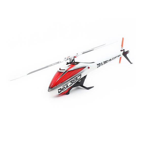
Summary of Contents for ALZRC DEVIL 380 FAST
-
Page 1: Instruction Manual
Instruction Manual Version 1.0 Juny 2016 German market english version... - Page 2 MANUAL DEVIL 380 FAST ALZRC DEVIL 380 FAST Manual Version 1.0 - Juny 2016 Dongguan TONY Electronic Technology Co., Ltd. www.alzrc.com For sales inquiries, please email: alzrchobby@163.com For information, please email: alzrchobby@163.com Attention: If you are a consumer and have questions or need of assistance, please contact the retailer where you made the purchased first.
- Page 3 MANUAL DEVIL 380 FAST CHAPTER 1 / INTRO PAGE 03...
-
Page 4: Table Of Contents
Assembling The Modules Installation of Swashplate Servos Tail Servo Assembly Installation of The Motor Installation of The ESC Installation of Flybarless Unit and RX Tail Assembly Installation of the Boom, Canopy Battery In flight Maintenance Exploded view PAGE 04 WWW.ALZRC.COM... -
Page 5: Specifications
1-SPECIFICATIONS SPECIFICATIONS Main rotor diameter: 856 mm Main blade length: 380 mm Tail rotor diameter: 192 mm Tail blade length: 70 mm Main shaft diameter: 8 mm Tail shaft diameter: 5 mm Spindle diameter: 5 mm Motor size: max. 41 mm diameter max. -
Page 6: Important Notes
Lack of care with assembly or maintenance can result in an unreliable and dangerous model. • Neither ALZRC nor its agents have any control over the assembly, maintenance and use of this product. • Therefore, no responsibility can be traced back to the manufacturer. You hereby agree to release ALZRC from any responsibility or liability arising from the use of this product. -
Page 7: Components And Box
3-COMPONENTS AND BOX INSIDE THE MAIN BOX THERE ARE: MANUAL BOX 2 BOX 4 BOX 1 BOX 3 INSIDE THE MAIN BOX BOX 1 Canopy Frames Blade Holder MAIN BOX Landing Gear Battery Support Tail Fin Assembly BOX 2 Combo Components (Optional) BOX 3 Tail boom Carbon Rod... - Page 8 4-CARBON FRAME The manufacturing process of the carbon parts often leaves micro-burrs and sharp edges. We recommend de-burring the edges to minimize the risks of electrical wire cuts, etc. This is particularly important in the areas shown in red. PAGE 08 CHAPTER 4 / CARBON FRAME...
- Page 9 4-CARBON FRAME LEFT MAIN FRAME ASSEMBLY NOTE Main Frame Use Loctite 243 to lock the bolts in the correct position. Tail Servo Support Plastic Battery Button Head Cap Support Special M2.5x6mm SUGGESTION Button Head Cap If you have the tail servo, we Special M2.5x6mm suggest you install it at this time as it will be more convenient to do so...
- Page 10 4-CARBON FRAME MAIN FRAME ASSEMBLY NOTE Use Loctite 243 to lock the bolts in the correct position. Button Head Cap Special M2.5x6mm Button Head Cap Button Head Cap Special M2.5x6mm Special M2.5x6mm Socket Head Cap Screw M2.5x10mm Finishing Washer M2.5 Finishing Plastic Washer M2.5...
-
Page 11: Transmission Assembly
5-TRANSMISSION ASSEMBLY MAIN SHAFT SUPPORT ASSEMBLY Socket Head Cap Screw M2.5x8mm Main Shaft Assembly Main Shaft Support Bearing Ø8xØ16x5mm Socket Head Cap Socket Head Cap Screw M2.5x8mm Screw M2.5x8mm Already Assembled Main Shaft Support Assembly SUGGESTION Shims Ø8xØ12x0,1mm (HC462-S) Tighten the three screw M2.5. After tightening, check the axial play of the main shaft. - Page 12 5-TRANSMISSION ASSEMBLY MAIN FRAME ASSEMBLY 120T PULLEY ASSEMBLY Socket Head Cap Screw Shouldered M2.5x18mm Already Assembled One Way Bearing Ø8xØ12x12mm 120T Pulley Plastic Servo Support Flanged Bearing Ø8xØ12x3,5 Flanged Bearing Socket Head Cap Ø8xØ12x3,5 Screw M2x5 Main Plate Assembly FRONT TAIL PULLEY ASSEMBLY Socket Head Cap Screw M2x8mm (HC008-S)
-
Page 13: Main Rotor Assembly
6-MAIN ROTOR ASSEMBLY RADIUS ARM ASSEMBLY ... X 2 RADIUS PLASTIC ARM ASSEMBLY ... X 2 Radius Arm Washer ø 2.1x ø 5 x0.5mm Socket Head Cap Screw M2x10mm Radius Arm Assembly Radius Plastic Arm Flanged Bearing Flanged Bearing ø 2x ø 5x2.5mm ø... -
Page 14: Assembling The Modules
7-ASSEMBLING THE MODULES SWASHPLATE ASSEMLY Head Assembly Uniball M2 Metric Hex Nylon Nuts M3 Swashplate Socket Head Cap Assembly Shouldered M3x16mm Swashplate Assemly Uniball M2 Uniball M2 Button Head Cap Special M2.5x6mm Button Head Cap Special M2.5x6mm Button Head Cap Special M2.5x6mm NOTE: Keep the distance between the end of the canopy retainer H0542 and the frame at approximately 12mm. -
Page 15: Installation Of Swashplate Servos
INSTALLATION OF SWASHPLATE SERVOS The linkage ball must be positioned approximately 13-15 mm out on the servo arm (figure 1), it is recommended to use the ALZRC / KST servo arm p/n [HA052]. Because of the 120° placement of the servos in the Devil380, the arms are difficult to access. For this reason it is advisable to ensure alignment of the servo arms (and sub trim) before installa- tion of the servos in the model (figure 2). - Page 16 8-INSTALLATION OF SWASHPLATE SERVOS PAGE 16 CHAPTER 8 / INSTALLATION OF SWASHPLATE SERVOS...
-
Page 17: Tail Servo Assembly
9-TAIL SERVO ASSEMBLY The distance between the servo spline and the ball Uniball M2 5H6 Socket Head Cap M3x6mm must be between 13-15 mm. You can use the ALZRC servo horn. Socket Head Cap M2x8mm Tail servo Servo Spacer Servo Spacer Socket Head Cap Screw M2.5x10mm... -
Page 18: Installation Of The Motor
10-INSTALLATION OF THE MOTOR TRANSMISSION SETUP It is important to choose the right reduction ratio to maximize efficiency based on your required flight performance. It is possible to optimize any motor and battery combination. It is recommended to use wiring and connectors appropriate for the currents generated in a helicopter of this class. If you are using a head speed calculator which requires a main gear and pinion tooth count, use 120 teeth for the main gear and the tooth count of your pulley as the pinion count. - Page 19 10-INSTALLATION OF THE MOTOR NOTE Correct position for the motor wires. Motor Pulley 21T Cone Point Set Screws M3x6mm Flat Head Socket Cap M3x5mm Motor Support Socket Head Cap Screws M2.5x8mm Finishing Washer M2.5 Socket Head Cap Screws M2.5x8mm Motor Metrix Hex Nylon Nut M4 Washer...
-
Page 20: Installation Of The Esc
10-INSTALLATION OF THE MOTOR MOTOR BELT TENSION • Assemble the motor and pulley to its mounting plate. • Install the motor assembly in the helicopter. • It is easy to install the belt with the motor assembly pushed back towards the helicopter as far as it can go. •... - Page 21 11-INSTALLATION OF THE ESC NOTE : DE-BURR THE SIDE FRAMES We recommend de-burring the edges of the carbon parts in areas where electrical wires run.(See Page 4). ESC INSTALLATION The speed controller (ESC) is installed in the front of the helicopter. Figure 1 and Figure 2 show the mounting area.
-
Page 22: Installation Of Flybarless Unit And Rx
12-INSTALLATION OF FLYBARLESS UNIT AND RX FLYBARLESS CONTROL UNIT AND RX INSTALLATION We suggest the use of a “single unit” FBL system (all in one type unit). This allows for easier wire routing considering the small size of this helicopter. Position 1 can be used to install the FBL unit. -
Page 23: Tail Assembly
13-TAIL ASSEMBLY TAIL PITCH SLIDER ASSEMBLY TAIL ROTOR HUB ASSEMBLY Already Assembled. Tail Damper eg: Microlube GL261 Tail Pitch Slider 03 Flanged Bearing Tail Spindle ø 7x ø 11x3mm Tail Pitch Slider 01 Tail Shaft Flanged Bearing Tail Pitch Slider 02 ø... - Page 24 13-TAIL ASSEMBLY TAIL SIDE PLATE ASSEMBLY BELL CRANK LEVER ASSEMBLY Flanged Bearing Cross Tail Case Tail Side ø 2.5x ø 6x2.5mm Aluminum Case Tail Pin Spacer Arm ø 2.5x ø 4x6.3mm Bell Crank Lever Uniball M3x 4 H3 Socket Head Cap Screw M2.5x6mm Flanged Bearing Flanged Bearing...
- Page 25 13-TAIL ASSEMBLY NOTE We suggest to clean the sticking surface with sand paper. LOCKING ELEMENT TAIL ASSEMBLY ..X 2 TAIL BOOM ASSEMBLY Double Locking Element Sided Tape Tail Assembly Locking Element Tail Already Assembled Red / White Tail Boom Double Sided Tape Metric Hex...
-
Page 26: Installation Of The Boom, Canopy
14-INSTALLATION OF THE BOOM, CANOPY Socket Head Cap Screw M2.5x10mm Finishing Washer M2.5 Finishing Washer M2.5 Socket Head Cap Screw M2.5x10mm Tail System Assembly NOTE Please allow plenty of time for the glue to cure before inserting plastic ball link onto the threaded rod. Threaded Rod Threaded Rod Plastic... - Page 27 14-INSTALLATION OF THE BOOM, CANOPY BOOM ASSEMBLY Insert the boom. This operation is easier fitting into the main frame at a slight angle [Fig.1]. To facilitate boom insertion, you can also unscrew the two bolts that hold the tail servo support tray. * Tighten the M8 nut with HA016 special tool supplied.
- Page 28 14-INSTALLATION OF THE BOOM, CANOPY TAIL BELT TENSION *Check for the proper assembly of the tail boom. *Loosen the tail case by loosening the 4 M2.5 screws. *Install the belt onto the front pulley in the correct direction of rotation (figure 1). *Rotate the tail drive several times by hand.
-
Page 29: Battery
15-BATTERY BATTERIES The Devil 380 has a quick release battery tray system. The batteries must be installed onto the battery tray to take advantage of the quick release locking system. Install the battery to the battery tray using double sided tape and the long Velcro straps included (Fig 1 and Fig 2). Make sure to find the right position of the battery to optimize the center of gravity. -
Page 30: In Flight
16-IN FLIGHT OPERATIONS BEFORE FLIGHT *Set up the transmitter and the flybarless system with utmost care. *It is advisable to test the correct settings of the transmitter and flybarless system without main blades and tail blades fitted. *Check that all wiring is isolated from the carbon/aluminum parts. It is good practice to protect them at the points where they are at most risk. -
Page 31: Maintenance
17-MAINTENANCE MAINTENANCE *On the Devil 380 Fast, some areas to look for wear include: - Motor belt - Tail belt - Dampers *The most stressed bearings are definitely those on the tail shaft and the thrust bearings. Check them frequently. All other parts are not particularly subject to wear. -
Page 32: Exploded View
18-EXPLODED VIEW, CARBON FRAME Main Frame Name Specification Quantity Finishing Washers M2. Aluminum Plastic Lading Gear Plastic Plastic Battery Support Plastic Tail Servo Support Plastic Main Frame Carbon Fiber Battery Tray Support Carbon Fiber Battery Aluminum Block Aluminum Button Head Cap Screws M2x5mm Button Head Cap Screws M2.5x6mm... - Page 33 18-EXPLODED VIEW, TRANSMISSION ASSEMBLY Transmission Assembley Transmission Assembley Name Specification Quantity Name Specification Quantity Finishing Washer M2.5 Aluminum Socket Head Cap Screws M2.5x8mm 21T Motor Pulley ASM Aluminum Head Cap Screws Shouldered M2.5x15mm 120T Main Pulley Aluminum Socket Head Cap Screws M2.5x18mm Front Tail Pulley ASM Aluminum...
- Page 34 18-EXPLODED VIEW, HEAD SYSTEM Head System Head System Name Specification Quantity Name Specification Quantity Washer ø 7,5x ø 10x0,5 Socket Head Cap Screws M2 x 8mm Plastic Linkage Ball Socket Head Cap Screws M2 x 10mm Swashplate 01 Aluminum Socket Head Cap Screws M2.5 x 8mm Swashplate 02 Aluminum...
- Page 35 18-EXPLODED VIEW, TAIL SYSTEM Tail System Name Specification Quantity Uniball M3 ø 5 H6 Transmission Assembley Plastic Ball Link M2,5 Grip Link Bushing Brass Name Specification Quantity Tail Pitch Slider 01 Aluminum Washer ø 2 ø 4.5x0.5 Tail Pitch Slider 02 Aluminum Tail Damper Derlin...
- Page 36 4. Rotor blades can rotate at very high speeds! Be aware of the danger they pose. 5. Always keep the model at a safe dsitance from other pilots and spectators. 6. Avoid maneuvers with trajectories towards a crowd. 7. Always mantain a safe distance trom the model ALZRC Devil380 Fast Instruction Manual 2016...
Need help?
Do you have a question about the DEVIL 380 FAST and is the answer not in the manual?
Questions and answers