Table of Contents
Advertisement
Advertisement
Table of Contents

Subscribe to Our Youtube Channel
Related Manuals for Vimar CLIMAPHONE


Summary of Contents for Vimar CLIMAPHONE
- Page 1 Instructions manual 01913 GSM Chronothermostat CLIMAPHONE...
- Page 2 Space set aside for noting down the three digits of the PIN of a password.
-
Page 3: Table Of Contents
Table of Contents Main operations for the user � � � � � � � � � � � � � � � � � � � � � � � � � � � � � � � � � � � � � � � � � � � � � � � � � � � � 2 1. -
Page 4: Main Operations For The User
MAIN OPERATIONS FOR THE USER The purpose of this section is to provide the user with guidelines on the current operations carried out on the GSM chronothermostat 01913� • Setting date and time - Press button ; the display will only show the arrow at the top to indicate the day and time to set� - Use button to move the arrow onto the current day�... - Page 5 - After selecting “Timed Manual” mode it is possible to change the set temperature value with button ; this change will be confirmed automatically after approximately 5 seconds� After setting the chronothermostat in “Timed Manual” mode, it is possible to change the duration with button and then press to confirm�...
- Page 6 • Summer/winter selection This function is used if it is necessary to control not only the heating system, but also the air-conditioning system with the chronothermostat� - Press and hold down button ; the display will show SEt together with the (winter) symbol or together with (summer) symbol�...
-
Page 7: Description
1. DESCRIPTION Electronic chronothermostat for ambient temperature control (heating and air-conditioning) with GSM phone communicator incorporated� Daily/weekly programming, change-over relay output 5(2) A 230 V~, one supplementary output and one digital input, remote control via SMS, power supply 120-230 V~, surface mounting, white 2. -
Page 8: Important Warnings
5. IMPORTANT WARNINGS To ensure optimal operation and use of the GSM chronothermostat 01913, pay attention to the following points: • As regards the type of SIM card, you should make a contract with your preferred telephone carrier� If you choose a pay-as-you-go SIM, periodically check the remaining credit and the expiry date� CAUTION: The chronothermostat 01913 cannot use SIM cards of the phone carrier 3 ®�... -
Page 9: 6�1 Installation Operations
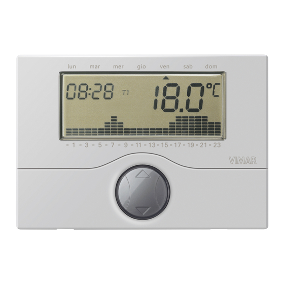
6.1 Installation operations 7. FRONT VIEW, CONTROLS AND DISPLAY 1. Day of the week� 2. Display� 3. Current time� 4. Room temperature� 5. Daily pattern of the current program� 6. “Mouse” button to control the basic functions� 7. Buttons for programming the functions� 8. -
Page 10: Connections
8. CONNECTIONS Circulation pumps, burners, solenoid valves Motorized valves CLOSES OPENS... - Page 11 Digital input for signalling alarms N L IN N INPUT CONTACT Output to control a generic load AUXILIARY RELE’ AUSILIARIO RELAY...
- Page 12 Inserting/removing backup batteries CAUTION! Before inserting the batteries cut off the supply voltage with the isolating device (main switch)� AAA NiMH 1,2 V IMPORTANT! Never use non-rechargeable batteries for any reason whatsoever; CAUTION! this is to avoid the risk of them In case of replacement, dispose of batteries in the exploding�...
- Page 13 Inserting the SIM card 1. Opening 2. Inserting SIM CAUTION! Disable the request for the PIN code on the SIM card being inserted� 3. Closing...
- Page 14 Important warnings for using the SIM card To ensure correct operation of the SIM card inserted in the GSM chronothermostat 01913, pay attention to the following points: • Contract SIM cards can be used to avoid a lack of credit or expiration of the SIM making the GSM chronothermostat unusable�...
-
Page 15: Functions Of The Buttons
9. KEY FUNCTIONS utton • B Enables entering the “Programming” function and selecting the day to program and copying the program (with “Automatic” mode)� • Button Enables entering the “Programming” function and selecting the time to program (with “Automatic” mode)� Enables activating and setting the duration in hours of the “Timed Manual”... - Page 16 - TIMED MANUAL. Used to set the chronothermostat in the “Manual” operating mode for a specific period of time (up to 99 hours); at the end of this time, the device sets the operating mode that had previously been selected� - AUTOMATIC.
-
Page 17: Programming
10. PROGRAMMING Make the electric connections, install the base of the appliance, insert the batteries, insert the SIM card (after previously disabling the request for the PIN code) and finally connect the chronothermostat to the relevant base� • Setting date and time Before beginning to program the chronothermostat, it is advisable to set the current day and time�... - Page 18 - Press button to confirm and pass on to setting the temperature T3; the display will show the reference value blinking� - Use button to set the desired temperature T3� - Press button to confirm; the display will show the dIFF icon and the relevant temperature differential blinking at 00�2°C�...
- Page 19 After setting the temperature value for the time 23:00, press: • button to confirm the program set for Monday and move on to set the next day; • button to copy the program of the current day to one of the other days of the week� After pressing button the display shows: - a fixed ...
-
Page 20: Operation
11. OPERATION Once the chronothermostat has been programmed, it can be put into operation� If the relay is activated, the symbol is displayed in the winter (heating) or the symbol in the summer (air-conditioning)� • Setting manual operation - Repeatedly press button until the display shows the symbol MAn alongside the blinking value of the temperature�... - Page 21 - Use button to select the desired temperature value then press button to confirm or button to cancel the operation� If the setting is not confirmed within approximately 40 seconds, the chronothermostat will return to the previously set operating mode� - After selecting “Timed Manual”...
- Page 22 • Timed switch-off - Repeatedly press button until the display shows OFF and, alongside the temperature value, the OFF symbol blinking - Press button ; the display will show two blinking digits indicating the number of hours (h) to set� - Use button to select the desired number of hours (from 1 to 99) then press button to confirm�...
- Page 23 • Summer/winter selection This type of function is only used when, besides the heating system, it is also necessary to control the air-conditioning system with the chronothermostat� - Press and hold down button ; the display will show SEt together with the (winter) symbol or together with (summer) symbol�...
- Page 25 Managing the chronothermostat 01913 via SMS text messages...
-
Page 26: Configuration
12. CONFIGURATION 12.1 DEFAULT VALUES Parameter Description Default value Permissible values General settings min 4 numerical digits User Code Used to access the GSM chronothermostat functions 1234 max 10 numerical digits Phone number Telephone numbers to save for sending SMS alarm max 8 phone numbers of Blank table... - Page 27 Parameter Description Default value Permissible values Chronothermostat settings Personalization Personal text to identify the chronothermostat in the max 20 alphanumeric Blank “label” SMS commands (C1 always remains valid) characters Parameter Description Default value Permissible values Auxiliary output settings Personalization Personal text to identify the auxiliary output in the SMS max 20 alphanumeric Blank “label”...
-
Page 28: 12�2 Start-Up Procedure
12.2 START-UP PROCEDURE 1� Make sure you have inserted the batteries and made all the necessary connections according to the required type of installation: • Power supply terminals� • Relay terminals for the connection to the boiler� • Digital input terminals (only if alarm signal detection is required) •... -
Page 29: 12�4 Procedure For Restoring The Initial Data Of The Gsm Module
Note. • If there is no GSM signal no histogram is shown� • The level of signal 1 is represented by a horizontal histogram that covers the entire length of the display� • The level of signal 2 is represented by a similar histogram to the one used for representing temperature level T1 (at the bottom right of the display)�... -
Page 30: 12�5 Using Sms Text Messages
Caution: the procedure just described does not affect the settings of the chronothermostat part; these settings are in fact restored to the initial values with button (see Chap� 9 on page 14 of this manual)� 12.5 USING SMS TEXT MESSAGES The GSM chronothermostat 01913 can receive SMS messages through which it is possible to configure, control and request the current status of the device;... -
Page 31: General Configuration
13. GENERAL CONFIGURATION 13.1 SETTING THE LANGUAGE The GSM chronothermostat 01913 enables user interaction via SMS messages, available in the following languages: Italian, English, French, German and Spanish� The choice of language used for the SMS messages can be made both via SMS and by using the EasyTool Professional LT software (see the instructions manual supplied with art�... - Page 32 The default User code is 1234 and can be changed both with an SMS message and with the EasyTool Professional LT program� To change the User code send an SMS in the form of: <user code>.COD.<new code> - If the sent code has more than 10 digits, the GSM chronothermostat will send the following SMS error message: GSM-01913 1/1 Error...
-
Page 33: 13�3 Phone Number Configuration
13.3 PHONE NUMBER CONFIGURATION The GSM chronothermostat 01913 enables sending SMS alarm messages to at most 8 different telephone numbers; the following points illustrate the functions for managing these numbers� Read: used to check the phone numbers saved in the 8 positions� ... -
Page 34: 13�4 Configuration For Redirecting To A Phone Number
Example� If the set user code is the default and you want to set the number 333778899 in position 1, send the following SMS: 1234.NUM1.333778899 Delete: used to delete a telephone number saved to one of the 8 positions; the procedure does ... - Page 35 The GSM chronothermostat will send the following SMS response message: GSM-01913 1/1 SMS redirection on number of index 1 To turn off this redirecting function, send the following SMS: <user code>.RED.NUM0 (zero) The GSM chronothermostat will send the following SMS response message: GSM-01913 1/1 SMS redirection Disabled...
-
Page 36: 13�5 Sim Credit Request Configuration (For "Pay-As-You-Go" Contracts)
13.5 SIM CREDIT REQUEST CONFIGURATION (FOR “PAY-AS-YOU-GO” CONTRACTS) The GSM chronothermostat 01913, after preliminary configuration via SMS, is able to make remaining credit requests to the telephone carrier of the SIm card used on the device and redirect them to the user making the request�... -
Page 37: 13�6 Configuring Sms Alarm Messages
13.5.2 Deleting credit request parameters The operator parameters set as described in the previous paragraph are deleted after sending the following SMS: <code>.SIMCREDITSET.0 13.5.3 Reading credit request parameters The operator parameters set as described in the previous paragraph are read after sending the following SMS: <code>.?SIMCREDITSET 13.5.4 Request for reading the remaining credit... - Page 38 The SMS alarm messages are composed, as we will see below, by linking two or three text messages together depending on the type of alarm message, that is to say: - the first message is predefined; - the other messages are optional and can be changed by the user� The following table shows the parts forming an SMS alarm message�...
- Page 39 The Address Msg. is optional and is represented by text that can be customized by the user who can, for example, summarize the data on the user or on the location of the house where the chronothermostat is installed (for setting the Address Msg� see paragraph 13�6�1�8 on page 41)� Note: After setting the Address Msg�...
- Page 40 13.6.1.2 Setting the input activation mode This setting requires selecting two possible options: activation on closing (equivalent to normally open) or activation on opening (equivalent to normally closed)� For activation on closing, send the following SMS message: <user code>.I1.C Note: No response SMS message is required from the chronothermostat 01913� Example�...
- Page 41 13.6.1.4 Setting the input deactivation time This setting enables defining a time interval for deactivating the input� The chronothermostat detects the state of deactivation only when the alarm condition has not been detected for at least the entire duration of the set deactivation time� For setting the input deactivation time send the following SMS message: <user code>.I1.TOFF.<time>...
- Page 42 GSM-01913 1/1 SMSAI: <list of associated phone number indices> SMSAR: <list of associated phone number indices> SMSAT1: <list of associated phone number indices> SMSAT0: <list of associated phone number indices> Example� Let us suppose that the set user code is the default 1234 and: - the input SMS alarm message has been associated with the telephone numbers 1, 2 and 3;...
- Page 43 13.6.1.7 Customizing the input SMS label This setting enables defining text to associate with the input so that the SMS alarm message also provides a description of it� For setting the input SMS label send the following SMS message: <user code>.I1.STR.<text> where <text>...
- Page 44 For the Address text, send the following SMS <user code>.ADDR.0 where 0 is the number zero� Note: No response SMS message is required from the chronothermostat 01913� Example� If the set user code is the default 1234 and you want to delete the Address text, send the following 1234.ADDR.0 To see (for example, if forgotten) the text associated with the Address Msg�...
- Page 45 Example� If the set user code is the default 1234 and: - the SMS input label has been set with the text “boiler shutdown”; - the input alarm has been enabled; - the set mode is active on closing (normally open); - the activation and deactivation times are 1s�...
- Page 46 13.6.2 Alarm for temperature exceeding the upper temperature threshold value The GSM chronothermostat can send an SMS alarm message if the temperature exceeds the threshold set by the user; this alarm condition is detected when the measured temperature is greater than the set upper threshold value (indicated by Tsup) by at least 0�1°C�...
- Page 47 The SMS alarm message is formed in this way: Temperature alarm! Tmis: <temperature value> Address (option) Tsup: <upper temperature threshold value> The configuration operations that, via SMS, can be performed on this alarm message are given in the following points� 13.6.2.1 Enabling or disabling higher temperature alarm management This option, if enabled, allows the chronothermostat to check the measured temperature continuously in order to detect exceeding the set upper threshold value and warn the user about it with an SMS...
- Page 48 Example 1� If the set user code is the default 1234 and you want to set the value of Tsup to 35�6°C, send the following SMS: 1234.ATEMP.AT1.35,6 Example 2� If the set user code is the default 1234 and you want to set the value of Tsup to 34°C, send the following SMS: 1234.ATEMP.AT1.34 13.6.2.3 Associating the alarm with the telephone numbers where the SMS message is to be sent...
- Page 49 13.6.2.4 Deleting the association of the alarm with the telephone numbers where the SMS message is to be sent This setting enables deleting the telephone numbers to which the SMS message must be sent� The procedure requires no response from the chronothermostat 01913� Send the following SMS message: <user code>.SMSAT1.NUM.0 where 0 is the number zero�...
- Page 50 13.6.2.7 Reading higher temperature alarm settings This function allows reading the settings associated with the alarm for the temperature being higher than the value of Tsup� The SMS message to send is the following one: <user code>.?AT1 The chronothermostat will send an SMS reply message with the following format: GSM-01913 1/1 ENABLED:ON/OFF AT1:XX,X degrees...
- Page 51 13.6.3 Alarm for temperature lower than the lower temperature threshold value The GSM chronothermostat can send an SMS alarm message if the temperature is lower than the threshold set by the user; this alarm condition is detected when the measured temperature is less than the set lower threshold value (indicated by Tinf) by at least 0�1°C�...
- Page 52 Note: The DTA has a predefined value that is already set and is optimal for most installation applications; if you change it, bear in mind that, if there are considerable variations in temperature around the set threshold value, too low a value assigned to the DTA could cause numerous SMS alarm messages to be sent out�...
- Page 53 13.6.3.2 Setting the lower temperature threshold This option is used to set the value of the lower threshold Tinf� To enable it, send the following SMS message: <user code>.ATEMP.AT0.XX,X where XX.X represents the value of Tinf to enter; the possible values to set must lie in the range between 0°C and 40°C�...
- Page 54 The chronothermostat 01913 will send a response SMS message with the list of all the associations between the phone numbers and the types of SMS alarm messages: GSM-01913 1/1 SMSAI: <list of associated phone number indices> SMSAR: <list of associated phone number indices> SMSAT1: <list of associated phone number indices>...
- Page 55 13.6.3.7 Reading lower temperature alarm settings This function allows reading the settings associated with the alarm for the temperature being lower than the value of Tinf� The SMS message to send is the following one: <user code>.?AT0 The chronothermostat will send an SMS reply message with the following format: GSM-01913 1/1 ENABLED:ON/OFF AT0:XX,X degrees...
- Page 56 13.6.4 Alarm for no mains power/restored mains power The GSM chronothermostat can send a “No Mains Power” SMS message if there is a power failure in the dwelling (blackout)� In addition, at the moment when the mains power is restored, the chronothermostat can send a “Restored Mains Power”...
- Page 57 To disable it, send the following SMS message: <user code>.AR.OFF Note: No response SMS message is required from the chronothermostat 01913� Example If the set user code is the default 1234 and you want to disable management of the alarm for no mains power/restored mains power, send the following SMS: 1234.AR.OFF To read the setting made on the alarm for no mains power/restored mains power, send the following...
- Page 58 13.6.4.2 Setting the warning times of the alarms for no/restored mains power This option allows separately setting the time (in seconds) beyond which the SMS alarm messages will be sent for “No Mains Power” and “Restored Power Supply”� Obviously, the SMS warning of the alarm is not sent in cases of momentary variations in power, whether failing or returning, that last less than the set values of TOFF and TON;...
- Page 59 13.6.4.3 Associating the alarm with the telephone numbers where the SMS message is to be sent This setting enables associating the SMS alarm message with up to 8 telephone numbers to which the message must be sent� The procedure requires no response from the chronothermostat 01913� Send the following SMS message: <user code>.SMSAR.NUM.<n1...n8>...
- Page 60 13.6.4.4 Deleting the association of the alarm with the telephone numbers where the SMS message is to be sent This setting enables deleting the telephone numbers to which the SMS message must be sent� The procedure requires no response from the chronothermostat 01913� Send the following SMS message: <user code>.SMSAR.NUM.0 where 0 is the number zero�...
-
Page 61: 13�7 Auxiliary Output Management
13.7 AUXILIARY OUTPUT MANAGEMENT The GSM chronothermostat 01913 is equipped with an auxiliary output to control a generic load� This load must be controlled solely via an external auxiliary relay (not supplied)� The functions that can be used for managing the auxiliary output are given in the following points� 13.7.1 Customizing the SMS label for the auxiliary output This setting enables defining a text to associate with the auxiliary output;... - Page 62 13.7.2 Two-position stable mode settings The operation of the auxiliary output can be configured as two-position stable; this setting is described in the following table: COMMAND STATUS DESCRIPTION Auxiliary output on The auxiliary output remains in the on state until the next OFF command Auxiliary output off The auxiliary output remains in the off state until the next ON command To set the two-position stable mode, send the following SMS message:...
- Page 63 Note: No response SMS message is required from the chronothermostat 01913� Example� If the set user code is the default 1234 and you want to configure the auxiliary output as one-position stable with an activation time of 0�5 s, send the following SMS message: 1234.R1.MONO.05 13.7.4 Reading auxiliary output configuration This function enables viewing the configuration assigned to the auxiliary output�...
- Page 64 13.7.5 Activating the auxiliary output This function is used to activate the auxiliary output and, as a result, the load connected to it via the external auxiliary output� The SMS message to send is the following one: <user code>.R1.ON The chronothermostat will send an SMS message confirming activation: GSM-01913 1/1 R1 ON Example�...
-
Page 65: 13�8 Remote Control Of The Chronothermostat Settings
13.7.7 Reading auxiliary output status This function allows viewing the current status (on or off) of the auxiliary output� The SMS message to send is the following one: <user code>.R1.STATO The chronothermostat will send an SMS reply message with the following format: GSM-01913 1/1 <label R1>:ON/OFF Example�... - Page 66 To delete customizing the chronothermostat SMS label, send the following message: <user code>.C1.STR.O where 0 is the number zero� Note: No response SMS message is required from the chronothermostat 01913� Example� If the set user code is the default 1234 and you want to delete the customization text associated with the chronothermostat, send the following SMS message: 1234.C1.STR.0 13.8.2 Setting the automatic operation temperature levels...
- Page 67 13.8.3 Setting the seasonal heating/air-conditioning mode This function is used to set the chronothermostat operating mode on Heating or Air-Conditioning� To set the seasonal mode, send the following SMS message: <user code>.C1.RISC/COND where RISC represents the Heating mode while COND the Air-Conditioning mode� The chronothermostat will send an SMS reply message with the following format: GSM-01913 1/1 C1 AIR-CONDITIONING/HEATING...
- Page 68 13.8.5 Setting manual operation This function is used to set the chronothermostat operating mode on MANUAL� To set this mode, send the following SMS message: <user code>.C1.MAN.XX,X where XX,X represents the temperature to set (at most two whole numbers and one decimal)� The chronothermostat will send an SMS reply message with the following format: GSM-01913 1/1 C1 MAN...
- Page 69 13.8.7 Antifreeze setting This function is used to set the Antifreeze chronothermostat operating mode� To set this value, send the following SMS message: <user code>.C1.ANTIGELO.XX,X where XX,X represents the temperature to set (at most two whole numbers and one decimal)� The chronothermostat will send an SMS reply message with the following format: GSM-01913 1/1 C1 ANTIFREEZE...
- Page 70 13.8.9 Setting timed manual This function is used to set chronothermostat timed manual operation� To set this mode, send the following SMS message: <user code>.C1.MANTEMP.XX,X.YY where XX,X represents the temperature value to set and YY the number of hours (from 1 to 99) in which the chronothermostat must operate in Manual mode�...
-
Page 71: 13�9 Chronothermostat Firmware Version Request
The chronothermostat 01913 will send the following SMS response message: GSM-01913 1/1 Meas Temp:18.9 degrees Set Temp:20 degrees Mode:MAN 13.9 CHRONOTHERMOSTAT FIRMWARE VERSION REQUEST This function is used to view the firmware version of the GSM chronothermostat 01913� The SMS message to send is the following one: <user code>.INFO The chronothermostat will send an SMS reply message with the following format: GSM-01913 1/1... - Page 72 The display (in the temperature field) shows the state of the input (OFF or on)� 13.10.4 Viewing and changing the input configuration parameters This function is used to set and check the input configuration parameters (see paragraph 13�6�1 on page 36); to view and edit these configuration parameters proceed as follows: - enter the GSM menu;...
- Page 73 13.10.5 Viewing and changing auxiliary output status This is a test function used to verify the operation of the auxiliary output and external relay connected to it� Important: The auxiliary output MUST be used to control an external auxiliary relay and not to control the load directly�...
- Page 74 With button you can change this value� Note: Up to 10 s the increase is 0�1 s, after 10 s the increase is 1 s and after 60 s the increase is 1 min� When setting times of less than one minute the display shows tMOn SEC, while, for time values longer than one minute, the abbreviation shown is tMOn Min�...
- Page 75 13.10.8 Setting the password (PIN) on the GSM chronothermostat This function is used to set a three-digit password (also called PIN) to protect the configuration data of the HVAC control of the chronothermostat 01913� The password, that at first is disabled (default value 000), is enabled with the procedures described in this paragraph;...
- Page 76 6� Using button set the value of the first digit of the new password then press to confirm; the display (in the hours field) will show nEw Pin and, in the temperature field, the second digit of the password will blink� 7�...
-
Page 77: 13�11 Gsm Chronothermostat Control Via Easytool Professional Lt Software
13.11 GSM CHRONOTHERMOSTAT CONTROL VIA EASYTOOL PROFESSIONAL LT SOFTWARE The GSM chronothermostat 01913 can also be managed with the EasyTool Professional LT software by connecting the device to a personal computer via the interface 01998�U� The main functions that the application enables to carry out are the following: •... - Page 78 13.11.1 Connections for managing the chronothermostat via EasyTool Professional LT. 1� Detach the top of the chronothermostat from its base� 2� Arrange the housing for the flat cable in the base of the chronothermostat�...
- Page 79 3� Connect the interface 01998�U to the top of the chronothermostat with the flat cable and the specific connector�...
- Page 80 3� Reconnect the top of the chronothermostat to its base� IMPORTANT: To manage the GSM chronothermostat 01913 with the EasyTool Professional LT software, it is necessary for the device to be powered from the mains� For all the details concerning the procedures for managing the GSM chronothermostat 01913 with the EasyTool Professional LT program, please see the manual equipping art�...
-
Page 81: Main Characteristics
14. MAIN CHARACTERISTICS • Power supply: 120 - 230 V~, 50-60 Hz • 2 AAA NiMH 1,2 V rechargeable batteries for the power supply in case of black out; the chronothermostat 01913, with no mains power and starting from the condition of batteries charged, remains completely functional (that is with the GSM module active) for approximately two hours�... -
Page 82: Installation Rules
16. CONFORMITY R&TTE directive Standards EN 60730-1, EN 60730-2-7, EN 60730-2-9, EN 301 489-1, EN 301 489-7, EN 301 511 Vimar reserves the right to change the stated features of the products at any time and without notice... - Page 84 Viale Vicenza, 14 - 36063 Marostica VI - Italy Tel� +39 0424 488 600 - Fax (Italia) +39 0424 488 188 Fax (Export) +39 0424 488 709 01913IEN 03 1512 www�vimar�com VIMAR - Marostica - Italy...
Need help?
Do you have a question about the CLIMAPHONE and is the answer not in the manual?
Questions and answers