Table of Contents
Advertisement
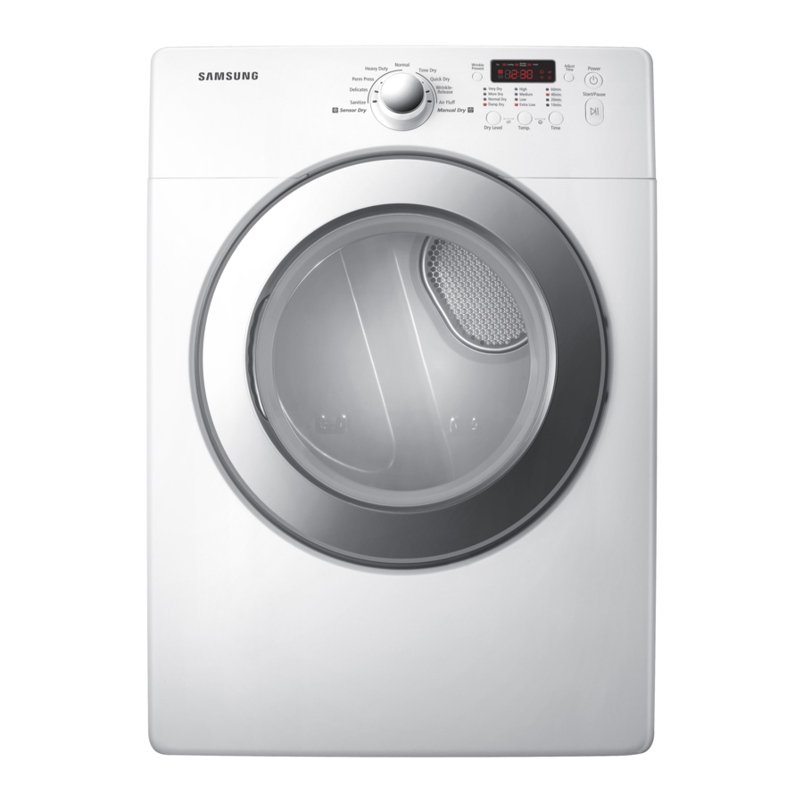
SERVICE
CLOTHES DRYER
DV231A**
Refer to the service manual in the GSPN (see the rear cover) for the more information.
CLOTHES DRYER
Basic Model : DV220AEW/XAA
(BIGBANG PROJECT)
Model Name : DV231AEW
(BIGBANG2 PROJECT)
Model Code : DV231AEW/XAA
DV231AGW/XAA
Manual
1. Safety Instructions
2. Features and Specifications
3. Disassembly and Reassembly
4. Troubleshooting
5. Exploded views and Parts list
6. PCB diagram
7. Wiring diagram
8. Schematic diagram
DV231AGW
CONTENTS
Advertisement
Table of Contents


Need help?
Do you have a question about the DV220AEW/XAA and is the answer not in the manual?
Questions and answers
The Samsung dryer turns on, but it doesn’t start. I know it’s not the belt because I’ve already checked it, but I don’t know if it’s a pool or not. I would like to get the electrical plug. Everything is good all night and the vents been cleaned trying to figure out what could it be model dk2220aewxaa
The Samsung dryer model DV220AEW/XAA may turn on but not start due to a faulty motor centrifugal switch. This switch is responsible for allowing the heating circuit to activate and may prevent operation if it's defective. If the heating element and other components test good and the control board relay is not closing, the motor or its centrifugal switch may need replacement.
This answer is automatically generated
Are most of the gas dryer parts (eg. fuses, thermostats) the same for DV220 and DV231? I can't find DV231AGW/XAA parts online. Thank you