DataCard SD260 Installation And Administrator's Manual
Hide thumbs
Also See for SD260:
- Installation and user manual (216 pages) ,
- User manual (156 pages) ,
- Installation and administration manual (116 pages)

Related Manuals for DataCard SD260


Summary of Contents for DataCard SD260
- Page 1 ® ™ ™ Datacard SD160 /SD260 Card Printers Installation and Administrator’s Guide November 2015 Part No. 527527-001, Rev. C...
-
Page 2: Trademark Acknowledgments
Notice Please do not attempt to operate or repair this equipment without adequate training. Any use, operation or repair you perform that is not in accordance with the information contained in this documentation is at your own risk. Trademark Acknowledgments Datacard is a registered trademark and service mark of Entrust Datacard Corporation in the United States and other countries. MasterCard is a registered trademark of MasterCard International Incorporated. Visa is a registered trademark of Visa International Service Association. All other product names are the property of their respective owners. Proprietary Notice The design and information contained in these materials are protected by US and international copyright laws. All drawings and information herein are the property of Entrust Datacard Corporation. All unauthorized use and reproduction is prohibited. Entrust Datacard 1187 Park Place Shakopee, MN 55379 Phone: 952‐933‐1223 Fax: 952‐933‐7971 www.entrustdatacard.com Copyright © 2015 Entrust Datacard Corporation. All rights reserved. - Page 3 MicroECC Copyright (c) 2013, Kenneth MacKay All rights reserved. Redistribution and use in source and binary forms, with or without modification, are permitted provided that the following conditions are met: – Redistributions of source code must retain the above copyright notice, this list of and the following disclaimer. – Redistributions in binary form must reproduce the above copyright notice, this list of conditions and the following disclaimer in the documentation and/or other materials provided with the distribution. THIS SOFTWARE IS PROVIDED BY THE COPYRIGHT HOLDERS AND CONTRIBUTORS "AS IS" AND ANY EXPRESS OR IMPLIED WARRANTIES, INCLUDING, BUT NOT LIMITED TO, THE IMPLIED WARRANTIES OF MERCHANTABILITY AND FITNESS FOR A PARTICULAR PURPOSE ARE DISCLAIMED. IN NO EVENT SHALL THE COPYRIGHT HOLDER OR CONTRIBUTORS BE LIABLE FOR ANY DIRECT, INDIRECT, INCIDENTAL, SPECIAL, EXEMPLARY, OR CONSEQUENTIAL DAMAGES (INCLUDING, BUT NOT LIMITED TO, PROCUREMENT OF SUBSTITUTE GOODS OR SERVICES; LOSS OF USE, DATA, OR PROFITS; OR BUSINESS INTERRUPTION) HOWEVER CAUSED AND ON ANY THEORY OF LIABILITY, WHETHER IN CONTRACT, STRICT LIABILITY, OR TORT (INCLUDING NEGLIGENCE OR OTHERWISE) ARISING IN ANY WAY OUT OF THE USE OF THIS SOFTWARE, EVEN IF ADVISED OF THE POSSIBILITY OF SUCH DAMAGE.
-
Page 5: Compliance Statements
Compliance Statements Liability The WARNING and CAUTION labels have been placed on the equipment for your safety. Please do not attempt to operate or repair this equipment without adequate training. Any use, operation, or repair in contravention of this document is at your own risk. Safety All Datacard® products are built to strict safety specifications in accordance with CSA/UL60950‐1 requirements and the Low Voltage Directive 2006/95/EC. Therefore, safety issues pertaining to operation and repair of Datacard® equipment are primarily environmental and human interface. The following basic safety tips are given to ensure safe installation, operation, and maintenance of Datacard equipment. • Connect equipment to a grounded power source. Do not defeat or bypass the ground lead. • Place the equipment on a stable surface (table) and ensure floors in the work area are dry and non‐slip. • Know the location of equipment branch circuit interrupters or circuit breakers and how to turn them on and off in case of emergency. • Know the location of fire extinguishers and how to use them. ABC type extinguishers may be used on electrical fires. • Know local procedures for first aid and emergency assistance at the customer facility. • Use adequate lighting at the equipment location. • Maintain the recommended temperature and humidity range in the equipment area. ... -
Page 6: Regulatory Compliance
Notice for USA (FCC notice) This equipment has been tested and found to comply with the limits for Class A computing devices, pursuant to Part 15 of FCC rules. These limits are designed to provide reasonable protection against harmful interference when the equipment is operated in a commercial environment. This equipment generates, uses, and can radiate radio frequency energy. If this equipment is not installed and used in accordance with this instruction manual, it may cause harmful interference to radio communications. Operation of this equipment in a residential area is likely to cause harmful interference in which case the user will be required to correct the interference at their own expense. Changes or modifications not expressly approved by the party responsible for compliance could void the user's authority to operate the equipment. Notice for Canada Industry Canada This digital apparatus does not exceed the Class A limits for radio noise for digital apparatus set out in the Radio Interference Regulations of the Canadian Department of Communications. Le présent appareil numérique n'émet pas de bruits radioélectriques dépassant les limites applicables aux appareils numériques de la classe A prescrites dans le Règlement sur le brouillage radioélectrique édicté par le ministère des Communications du Canada. RSS‐Gen, Issue 3, December 2010, Section 7.1.3 User Manual Notice This Device complies with Industry Canada License‐exempt RSS standard(s). Operation is subject to the following two conditions: 1) this device may not cause interference, and 2) this device must accept any interference, including interference that may cause undesired operation of the device. Cet appareil est conforme avec Industrie Canada RSS standard exemptes de licence(s). Son fonctionnement est soumis aux deux conditions suivantes: 1) ce dispositif ne peut causer des interférences, et 2) cet appareil doit accepter toute interférence, y compris les interférences qui peuvent causer un mauvais fonctionnement du dispositif. Notice for Europe The EU Declaration of Conformity can be found on Datacard.com We hereby certify that this printer complies with EMC Directive 2004/108/EC, R&TTE Directive 1999/5/EC, and the EU RoHS Directive EU Directive 2011/65/EC. This printer conforms to Class A of EN 55022 and to EN 301 489‐5. Operation of this equipment in a residential environment may possibly cause interference. In the event of interference, the users, at their own expense, will be required to take whatever measures are necessary to correct the problem. - Page 7 Notice for Europe and Australia This is a Class A product. In a domestic environment this product may cause radio interference, in which case the user may be required to take adequate measures. Notice for China (Simplified Chinese) 警告 此为 A 级产品,在生活环境中, 该产品可能会造成无线电干扰。 在这种情况下,可能需要用户 对干扰采取切实可行的措施。 Notice for Taiwan (Traditional Chinese) Notice for Japan Japanese Voluntary Control Council for Interference (VCCI) class A statement Korea Communications Commission (KCC) statement...
- Page 8 California Proposition 65 Compliance WARNING: This product contains chemicals, including lead, known to the State of California to cause cancer, and birth defects or other reproductive harm. Wash hands after handling. Datacard Group believes that its products are not harmful when used as designed. However, the above warning is made in compliance with the State of California Safe Drinking Water and Toxic Enforcement Act of 1986, which requires warning labels on products that may contain elements that the State of California considers harmful. viii...
-
Page 9: Revision Log
Revision Log SD160/SD260 Card Printers Installation and Administrator’s Guide Revision Date Description of Changes February 2015 First release of this document. May 2015 Updated for Card Printer Driver version 6.1; added rewrite capability to the SD260 November 2015 Updated for Card Printer Driver version 6.2... -
Page 11: Table Of Contents
Contents Chapter 1: Installation ............1 PC Requirements. - Page 12 Apply Topcoat ............. 23 Non-Printing Areas .
- Page 13 TroubleShooting Menu ............57 Testcard .
- Page 14 Cables and Power Supplies ........... . . 75 Data Cables .
-
Page 15: Chapter 1: Installation
This chapter describes system requirements and provides setup instructions for the Datacard® SD160 and SD260 Card Printers. Your installation may have additional requirements for a card production environment. Consult your system administrator to determine the optimum location for card production. For Card Printer Driver installation troubleshooting and card production troubleshooting information, refer to your printer’s Driver Guide and User’s Guide. PC Requirements Use a PC that meets or exceeds the following: A 32‐ or 64‐bit processor, running at 2 GHz or faster 4 GB or more memory (RAM) and at least 1 GB free space on the hard driver One of the following operating systems supported by the XPS Card Printer Driver: Windows 10, 32‐ or 64‐bit Windows 8.1, 32‐ or 64‐bit Windows 7, 32‐ or 64‐bit Windows Server 2012, R2 Windows Server 2008, 64‐bit USB 2.0 port or Ethernet network connection The SD160 card printer uses only a USB connection. It cannot connect via Ethernet. The SD260 card printer can be connected using either USB or Ethernet. A printer can use only one connection type. ID software or other card production software to capture and organize the data to print on each card SD160/SD260 Installation and Administrator’s Guide... -
Page 16: Ethernet Requirements
Ethernet Requirements You can connect many network printers to one PC. The maximum number of printers depends on the capacity of the network to deliver data to the printer. To install an SD260 printer on a network, the following components are required: An Ethernet network that uses the TCP/IP protocol and can run at 100 megabits per second, also called 100base‐T. Printers also support 10base‐T. An Ethernet cable to connect the printer to the network. An Ethernet cable is not supplied with the printer. A PC that meets the “PC Requirements” described on page 1, and is connected to and communicating with the network. USB Requirements You can connect up to eight card printers to a PC using USB cables. To install a printer using a USB connection, the following components are required: A high‐speed USB port. USB 2.0 is required. A USB 2.0 cable to connect the printer to the PC. A USB cable is supplied with the printer. A PC that meets the “PC Requirements” described on page 1. If you need to connect two card printers to a PC with one USB port, use a single, independently powered USB hub to which you can connect both printers. Electrical Requirements The power supply detects the input voltage and works within the range stated. Electrical Requirements Printer Model Input Output SD160 or SD260 110–240V/50–60 Hz/1.5 Amp 24V/3.0Amp/72W Installation... -
Page 17: Site Requirements
Model SD160/SD260 10.00 8.80 4.00 6.85 4.00 15.37 4.00 SD260 with smart 10.00 8.80 4.00 6.85 4.00 21.21 4.00 card Options such as a large output hopper and 200‐card input hopper add height to the printer. Additional clearance is required when using these options. Place the printer in an environment with temperatures ranging from 60° to 95°F (15° to 35°C). Use a single‐phase, 3‐wire, grounded receptacle. Place the system and its supplies in a clean office environment, keeping paper and foreign materials off of the equipment. Place the printer on a sturdy, level surface. Place the printer away from direct sunlight. Do not place the printer near heating ducts, fans, or other air vents. Do not use the printer for purposes other than the intended use. SD160/SD260 Installation and Administrator’s Guide... -
Page 18: Set Up The Printer
Set Up the Printer This section provides information about setting up the printer to print cards. Setup includes the following: Prepare the Printer Install Optional Equipment on page 8 Install the Card Printer Driver on page 13 Prepare the Printer To prepare the printer to print cards, load blank card stock into the input hopper, and load print ribbon and a cleaning sleeve onto the print cartridge. If you are printing rewritable cards, refer to “Prepare the Printer to Use Rewritable Cards” on page Load Cards If you are using a manual feed printer or are printing rewritable cards, skip this step and keep a supply of blank cards close to the printer. Do the following to load the input hopper: Open the input hopper. Load the cards into the input hopper. Cards can stick together. Slide or fan the cards to separate the edges before placing them in the hopper. Handle cards by their edges only. Refer to “Card Handling” on page 71 for more information. Insert ISO magnetic stripe cards with the stripe (back side) facing down and toward the right. Insert smart cards with the smart card chip facing up and toward the back of the hopper. A diagram inside the hopper shows the correct orientation for each type of card. Close the input hopper. -
Page 19: Load The Print Ribbon
Load the Print Ribbon Load the ribbon when you install the printer and when the ribbon runs out. (If you are using the rewritable option, refer to “Prepare the Printer to Use Rewritable Cards” on page Open the printer cover. Remove the print ribbon cartridge. Load a full roll of print ribbon (the blue spool) onto the spindle closest to the cartridge handle until it clicks into place. Place the silver take‐up spool on the spindle with the black gear until it clicks into place. Wind the take‐up spool counterclockwise one full turn. Load the Cleaning Sleeve Load a new cleaning sleeve with each new roll of print ribbon, if you notice debris on the printed cards, or if the cleaning sleeve is no longer sticky. The printer ships with the cleaning roller spindle in the accessory box. Locate the cleaning roller spindle and slide the spindle into the continuous cleaning sleeve (a). Place the spindle with cleaning sleeve onto the ribbon cartridge (b). Remove the protective wrapper from the cleaning sleeve (c). SD160/SD260 Installation and Administrator’s Guide... -
Page 20: Install The Ribbon Cartridge
Install the Ribbon Cartridge Install the assembled print ribbon cartridge into the printer. Open the printer cover. Hold the print ribbon cartridge by the handle and lower it into the printer with the handle toward the front of the printer. Make sure that the ribbon cartridge is correctly positioned in the guides. Close the printer cover. Press down on the ridges on the front of the cover to make sure that it latches completely on both sides. Installation... -
Page 21: Prepare The Printer To Use Rewritable Cards
Prepare the Printer to Use Rewritable Cards Open the printer cover and remove the print ribbon cartridge. Remove the print ribbon from the cartridge and set it aside. Make sure that the cleaning roller with the replaceable cleaning sleeve is installed. Return the print ribbon cartridge to the printer. Close the printer cover. Press down on the ridges on the front of the cover to make sure that it latches completely on both sides. Have rewritable cards available to insert into the printer. When you print rewritable cards, insert the cards one at a time. Make sure that the card is engaged in the pick rollers. The erase/rewrite process can cause the cards to bend slightly, which may prevent them from being picked from the input hopper. To print rewritable cards, you also must do the following: Enable rewritable printing in Printer Manager. Use the rewritable card settings to enable the rewrite option and specify the values to use. Refer to “Print” on page 44 for complete information about the Printer Manager settings. Specify rewritable card settings in the Card Printer Driver. For complete information about setting up the Card Printer Driver to print rewritable cards, refer to your printer’s Driver Guide. SD160/SD260 Installation and Administrator’s Guide... -
Page 22: Install Optional Equipment
Install Optional Equipment You can install additional equipment on the printer depending on your requirements. Install a Large Output Hopper The output hopper included with the printer holds about 25 0.030 in. (0.762 mm) cards. The printer also can be used with an optional large output hopper that holds up to 100 cards. The large output hopper kit includes two base sections and the large output hopper. The two base sections are identical, with hooks (marked by green circles) that attach to the bottom of the printer. To assemble the base, arrange the base sections back to back, as shown. Standard Output Hopper Large Output Hopper Base Sections You can remove the standard hopper and attach the large output hopper without using tools. Installation... - Page 23 Do the following to attach the printer to the bases, and to install the larger output hopper. You also can refer to the instructions shipped with the large output hopper kit. Position one base section with the open end facing the back of the printer. Lift the printer over the base section. Align the tabs in the base with the slots in the bottom of the printer. Push up to insert the four tabs in the slots, and then push the base forward to lock it to the printer. Position the other base section with the opening facing the front of the printer. Push up to insert the four tabs in the slots and then push the base back to lock it to the printer. Remove the 25‐card output hopper from the printer. Slide it out, similar to a drawer. Slide the 100‐card output hopper into the assembled base and printer. Make sure that the tabs (shown in circles in the illustration) secure the hopper to the printer. & T INTS The base sections contain drawers, useful for holding cards, cleaning swabs, or other frequently used items. The drawers can be opened from either the left or right side of the printer. The base and large output hopper remain attached when the printer is moved or carried. If you install the 100‐card output hopper, change the Printer Manager Printer Setting > Transport EjectHopperSpeed setting to Extended. This allows completed cards to stack properly in the larger output hopper. Refer to “Transport” on page 50 for complete information. SD160/SD260 Installation and Administrator’s Guide...
-
Page 24: Install The 200-Card Input Hopper
Install the 200-Card Input Hopper The standard input hopper can hold about 100 0.030 in. (0.762 mm) cards. The printers can be upgraded to use a 200‐card input hopper. The 200‐card input hopper kit includes the larger hopper with an attached cover. The standard hopper is easily removed and the 200‐card hopper can be installed without using tools. You also can refer to the instructions shipped with the 200‐card input hopper kit. Open the input hopper. Press the release tab located on the back wall of the hopper while lifting the hopper up and off the printer. Install the 200‐card input hopper by aligning the tabs with the slots on the printer. Hopper Release Tab Push the hopper down until it clicks into place. Load up to 200 cards in the hopper and close the hopper cover. The printer is ready to print cards. Installation... -
Page 25: Install The Optional Cable Lock
Install the Optional Cable Lock The cable lock is a user‐installed feature that does not require special tools to install. The package contains a Kensington® lock with keys, instructions, and a metal security plate. The security plate is installed in the printer and is designed to accommodate the T‐bar of the Kensington lock. Prepare the printer by installing the metal security plate: Tip the printer on its right side. Locate the security plate receptacle on the underside of the printer toward the back left side. Insert the security plate into the receptacle with the open end toward the printer. Follow the instructions included with the lock to complete the installation. SD160/SD260 Installation and Administrator’s Guide... -
Page 26: Plug In And Power On The Printer
Plug In and Power On the Printer Plug in the printer power cables and connect the printer to a facility power source. Press the P button on the front panel to power on the printer. The front panel LCD displays OWER Ready when the printer is ready to print. The LCD Ready display may differ slightly for some printer models. Installation... -
Page 27: Use The Front Panel
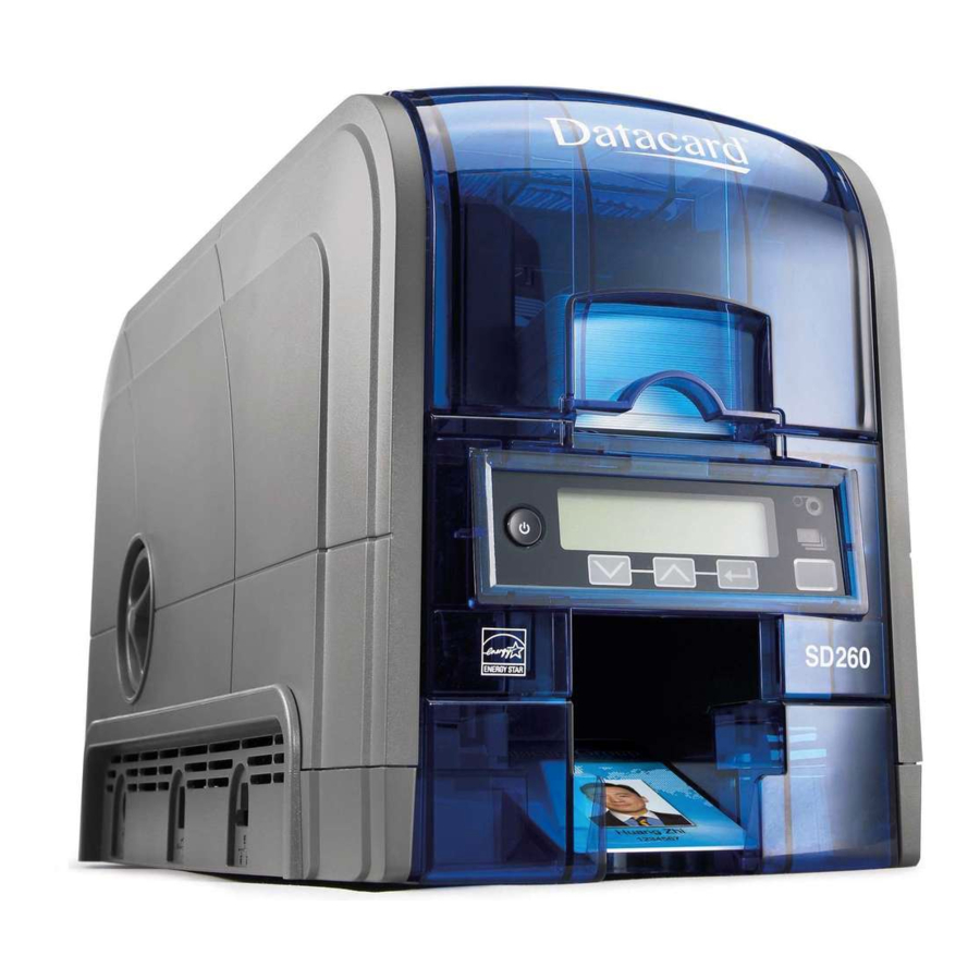
Use the Front Panel The front panel of the printer provides the controls you need to operate the system. Refer to the printer’s User’s Guide for complete information about using the front panel. LCD Panel Status Lights Ribbon Cards Power Button User Light & Down Up Enter User Button Arrow Arrow Install the Card Printer Driver The Card Printer Driver uses Microsoft XPS print technology to support printing from currently available Microsoft Windows applications. To use the SD card printer with the Card Printer Driver, you must install and configure the driver. Refer to your printer’s Driver Guide for complete information about installing and using the Card Printer Driver. SD160/SD260 Installation and Administrator’s Guide... - Page 28 Installation...
-
Page 29: Chapter 2: Elements Of Card Design
Magnetic Stripe Design on page 27 Smart Card Design on page 29 Settings for Card Design in Printer Manager on page 30 Basic Card Design Card design includes: Color and monochrome printing. Back of Card Magnetic Stripe The various types of data, such as Signature Panel name, account number, and special features such as a magnetic stripe or smart card chip. The layout of the data. Front of Card Printed Topcoat Optional ultraviolet (UV) printing for Smart Card Chip enhanced security. Photo Bar Code SD260L/SD360/SD460 Installation and Administrator’s GuideSD160/SD260 Installation and... -
Page 30: Printing Design
Printing Design Printing design includes color and monochrome printing, bar code printing, non‐printing areas, and card layout. Color Printing Color print ribbon is available in full‐panel and short‐panel styles. Full-Panel Ribbon Full‐panel color printing uses a print ribbon with three color panels: Y (yellow), M (magenta), and C (cyan). The ribbon also includes a K (black) panel and a T (topcoat) panel. The printer applies the YMC color panels to the card first, prints black components using the K panel, and then applies the T (topcoat) to protect the color image from damage. Full‐panel color print ribbons with an ultraviolet (UV) fluorescent panel, YMCKFT, also are available. YMCKFT ribbons are available for all printers and apply the topcoat panel over the printing to protect the images from damage. The UV printing is undetectable under normal lighting and is meant to provide another form of security. Refer to your printer’s Driver Guide or your card personalization software documentation for more information about setting up a card design that includes UV printing. The ribbon panel configuration that supports YMCKFT functionality can differ depending on your printer model. Short-Panel Ribbon Color print ribbon also is available in a short‐panel option. The color area for short‐panel ribbon is either 1.57 inches (40 mm) or 1.47 inches (37.5 mm), depending on the ribbon configuration. The ymc panels of short‐panel ribbon are approximately half the length of a full card. (In this guide, “ymc” in lowercase, instead of “YMC,” refers to “short‐panel” color panels.) When you print with short‐panel print ribbon, you define the location of the color area in the card design. Color printing begins when the software detects a color pixel and continues for the length of the ymc panels. Elements of Card Design... -
Page 31: Split-Ribbon Color Printing
Most types of cards, including cards with magnetic stripes and smart cards, can be printed using split‐ribbon printing. Options for color, monochrome, and topcoat are available when you use split‐ribbon printing. Manage Color Color management is the process of making color on the PC monitor and printed card appear as similar as possible. For color management, the card printer uses the sRGB color standard (standard Red, Green, and Blue color space). You specify the color management system in Printer Manager. Refer to “Print” on page 44 for more information. Print Text in Color The printer can print text in any color. Small characters are likely to be more readable if they are a sans‐serif font formatted as black and printed with the black (K) panel. Refer to “Print Text in Monochrome” on page 19. The printer supports 6‐point or larger text. Print Graphics in Color The printer produces full‐color images from most types of graphics. It can use BMP, JPEG, TIFF, and PNG file formats for photos and logos. Vector graphics, such as WMF and SVG files, have components such as shapes with lines and fills. Components defined as black normally print with the K panel. Because the printer uses the print ribbon panels in sequence (YMC first, then K), black images can print over color graphics. For the best appearance of color graphics, or to prevent backgrounds that are black from printing over colored images, use a color that appears black but is not, so that all parts of an image print with the YMC panels. For example, in the RGB color space, 0, 0, 0 is black (and prints with the K panel), but 0, 0, 5 is not black (and prints with the YMC panels). SD260L/SD360/SD460 Installation and Administrator’s GuideSD160/SD260 Installation and... -
Page 32: Monochrome Printing
Types of Color Images Cards can include both color photos and color logos. The logo is usually the same on each card, and the photo is unique. Follow these guidelines to obtain the best results for printing both logos and photos. Evaluate the color quality of the photos: Adjust the image capture system to get the best quality photos; work with distance, lighting, and camera settings to obtain consistent, high‐quality photos. Evaluate the quality of printed photos after the image capture system is optimized. Evaluate the other color areas of the card, such as text or logo: Check your card production application for settings that can help improve the printed color of text. Use an image editing application to adjust the color of a logo file for optimal printing. Monochrome Printing Monochrome printing prints cards using a single color. You can use a full‐color ribbon or a monochrome ribbon that has only one color. Monochrome Printing with Full-Color Ribbon Full‐color print ribbon includes a black panel. The black panel transfers to the card differently than the YMC panels. Text and bar codes are usually printed with the black panel. Full‐color print ribbon also prints any monochrome or one‐bit‐per‐pixel graphics using the K panel. Elements of Card Design... -
Page 33: Monochrome Ribbon
Monochrome ribbon produces single‐color cards. Monochrome ribbon can be any of the following: Alternating black and topcoat panels (KT or KTT ribbon) The printer applies black and one or two topcoat panels on the same side of the card. Continuous black (K ribbon) A continuous color, for example, green or silver (also called a K ribbon). Refer to “Monochrome Print Ribbon Kits” on page 67 for a list of available colors. Ribbon Saver Continuous monochrome printing with Datacard‐certified ribbon uses the Ribbon Saver feature. With Ribbon Saver, the printer begins using ribbon at a location that corresponds to the leading edge of the card. The printer continues to spool ribbon for the length of the image but no farther. The printer leaves a small margin between each card to avoid image overlap. Print Text in Monochrome Printing text using a K panel can make text look crisp, because it uses only one panel for printing. Fine text is more readable when printed with more power. You set the power for the K panel using Printer Manager. Refer to “Print” on page 44 for more information. The font used also affects legibility. The printer reliably prints 6‐point Arial font. Bold, sans‐serif fonts are more readable after printing than serif fonts, or fonts with thin strokes, as shown at right. In the example, fonts that print well are shown toward the top of the card. SD260L/SD360/SD460 Installation and Administrator’s GuideSD160/SD260 Installation and... -
Page 34: Rewritable Card Design
Rewritable Card Design The SD160 and SD260 printers allow you to erase and reprint multiple times on special rewritable cards. Rewritable cards are used in applications that contain variable, or changing, information, such as short‐term contractor or visitor badges, and customer loyalty cards. A rewritable card design includes the following elements: Static Area Static Elements Elements that always remain the same, such as a company name and logo, phone number, or website. Erase Area Variable Elements Elements that can change from user to user, such as a photo or expiration date. Where you place the variable elements determines how the card will be erased. Refer to your printer’s Driver Guide Static Area for more information about setting up the printer to use the rewritable option. Refer to “Print” on page 44 for information about the Printer Manager settings that control the rewritable function. Print Bar Codes Bar code design follows a set of standards based on the type of bar code produced. Bar codes contain a series of black lines (bars) separated by white areas (spaces). Each character of encoded data is represented by a set of bars and spaces. A bar code standard specifies the number and width of bars and spaces needed to encode a character. The standard also specifies the minimum size of the white area, or quiet zone, that surrounds the bar code. Refer to “Print Bar Codes With the Card Printer Driver” on page 22 for information ... -
Page 35: Bar Code Guidelines
Bar Code Placement Maintain the required quiet zone around the actual bar code, as shown in the illustration. Locate bar codes at least 0.25 inch (6.3 mm) from other printing and from the edge of the card. For best results, orient the card so that the bars are parallel to the long edges of the card, as shown. This orientation most accurately prints readable bar codes. Bar Code Size A lower density bar code is easier to read, because the bars are wider and spaced farther apart. The width of the narrow elements in the bar code must be large enough to be read consistently. The capabilities of the bar code reader can influence this. The bar code must be tall enough to be read under normal conditions. Bar Code Print Settings To achieve the best quality printing and improve the readability of the bar code, use the K (black) panel of color print ribbon to print the black bars. Bar codes printed with YMC panels are not as crisp and sharp as those printed with the K panel only. Infrared readers require that the K panel be used to print the bar code. The ANSI standard for bar code quality (X3.182) assigns a grade to a bar code to indicate its readability. Choose a K power value and bar code size to produce the grade your system requires. Refer to “Print” on page 44 for information about setting the K power value. SD260L/SD360/SD460 Installation and Administrator’s GuideSD160/SD260 Installation and... -
Page 36: Test Bar Codes
Test Bar Codes Always test the readability of bar codes under production conditions. Factors to consider include: If you print cards one at a time, print the samples using that method. If you print cards in batch (many cards sent to the printer at the same time), use a production‐sized batch and evaluate cards from the beginning, middle, and end of the batch. Use exactly the same card stock for testing that you use for production. The card stock can affect the readability of bar codes. Usually, a white surface that reflects light in many directions is needed. Test cards before purchasing production quantities. Include other card design components that you use in production, such as topcoat. Use the same bar code readers as users have, and test each card multiple times to simulate any wear the card might experience. Also test multiple cards. Card Design Changes That Affect Bar Codes If you make substantial changes to the way you produce cards, review your setup tasks to make sure that cards continue to have the quality you require. Changes that can affect bar codes include: Purchasing a new brand of card stock, which can change the color of some images. Changing to, or from, preprinted cards, which can change the color of some images. If you change the design of your cards, or if you start producing an additional card design, test each design as described in “Test Bar Codes” to make sure that the bar code prints as expected. Print Bar Codes With the Card Printer Driver The Card Printer Driver includes a setting that allows the printer to use the black (K) panel to ... -
Page 37: Apply Topcoat
Apply Topcoat Full‐color and UV printing fades if it lacks topcoat protection. Topcoat protects the printed image on the card. It is applied as an even, consistent film. Make sure that all color printing is covered with topcoat (except for areas such as a magnetic stripe, smart card chip, or signature panel). When a ribbon with a topcoat (T) panel is installed, the printer can apply topcoat to the card using the printhead. Most full‐ color ribbons include topcoat panels. Topcoat must be requested by the application sending the card to the printer. Most card production software requests topcoat automatically. Do not apply topcoat over the magnetic stripe, smart card chip, or signature panel of a card. To prevent topcoat application, you must specify a non‐printing area. Non-Printing Areas The card design can have areas where printing is not allowed. Such areas include a magnetic stripe, signature panel, or smart card chip. Card production software usually manages such non‐ printing areas automatically. If you do not use ID software, you can use the dimensions provided in the following sections for magnetic stripe and smart card non‐printing areas to customize your print and topcoat areas. Blocking for non‐printing areas typically extends 0.1 inch beyond the edges of a feature. The dimensions listed in the following sections include the extended blocking region. Print several cards using your card design and application to verify that printing and topcoat are applied as you intend. SD260L/SD360/SD460 Installation and Administrator’s GuideSD160/SD260 Installation and... -
Page 38: Standard Magnetic Stripe Non-Printing Area
Standard Magnetic Stripe Non-Printing Area The 3‐track magnetic stripe typically is on the back of the card, while the single‐track magnetic stripe is usually on the front of the card. The green arrow shows the direction the card travels through the printer. Use the following dimensions to prevent printing in the magnetic stripe area. 3‐track 3.37 in 1.46 in 0.66 in 85.6 mm 37.1 mm 16.8 mm 2‐track 3.37 in 1.57 in 0.55 in 85.6 mm 39.9 mm 14 mm Single‐track (JIS) 3.37 in 1.60 in 0.52 in 85.6 mm 40.6 mm 13.2 mm Standard Smart Card Non-Printing Area The smart card area typically is on the front of the card. The green arrow shows the direction the card travels through the printer. Use the following dimensions to prevent printing in the smart card area. 0.88 in 1.17 in 0.88 in... -
Page 39: Card Layout
Card Layout The arrangement or layout of components determines how well your card design works for users. Follow these guidelines to position card design components for best results. Margins Any unprinted area at the edge of the card or around the perimeter of a card feature is called the margin. Margins at the Edge of a Card The card printers can print edge to edge, which is the same as a margin of zero (0) or no margin. The card on the left shows a margin of white space at the outer edge of the card. The card on the right shows edge‐to‐edge printing. Edge‐to‐edge printing can require fine‐tuning the printer and the card design. Include this task as part of setup. Margins for Card Features Maintain a margin between printing and card features, such as a signature panel, magnetic stripe, or smart card chip. For best results, do not print closer than 0.1 inch (2.5 mm) from such a feature. SD260L/SD360/SD460 Installation and Administrator’s GuideSD160/SD260 Installation and... -
Page 40: Backgrounds
Backgrounds Use the following suggestions to help you select a background for a professional‐looking card. For best results, make sure that the background design does not emphasize the location of card features, such as embedded electronics. Consider using a white background for the card to achieve consistent professional results. Consider using smaller blocks of color, patterned areas, or gradients to highlight printed card features such as a name, photo, or logo. Avoid using a solid‐color background over a large area of the card. It can show flaws on the card (such as an uneven surface) or the location of card features (such as a smart card chip). Image Placement Use the following suggestions to help you locate important images, such as a photo, logo, or bar code. When placing images, avoid uneven areas and areas of high wear, which can result in inconsistent print quality. Do not place an important image on the front of the card in the same area as a magnetic stripe or other machine‐ readable feature. Frequent use of a card in a reader can wear away the image on the opposite side of the card. Do not place an important image directly on the opposite side of a signature panel. This can cause residue from the signature panel to interfere with printing on an adjacent card. Place the image above, below, or to the side of the panel. Do not place an important image directly on the opposite side of a smart card chip. The card might not be as flat in that area, and printing voids can occur. Elements of Card Design... -
Page 41: Magnetic Stripe Design
Magnetic Stripe Data Formats The module format (ISO or JIS) defines the type and format of the information to encode. The standard ISO format (also known as IAT) is a three‐track option. The JIS format is a single‐track option. Both formats include default data settings that determine how many characters can be encoded on each track, and which characters can be encoded. Your cards can use the default format for each track, or can use a different combination of tracks and data formats. Three-Track Option (ISO/IAT) The default data formats for a three‐track magnetic stripe option are: Track 1 — IATA Track 2 — ABA Track 3 — TTS This combination is often abbreviated IAT. This format is also called ISO format. IATA (International Air Transport Association) The maximum number of characters for IATA format data is 76 characters. These characters can include spaces, uppercase alphabetic characters (A–Z), numeric characters (0–9), and the following special characters: ! # $ % ' ( ) * + , ‐ . / ; : < @ > = ^ ] \ [ " & _ ABA (American Bankers Association) The maximum number of characters for ABA format is 37 characters. Numeric characters (0–9) and the following special characters are allowed: : ; < = > TTS (Thrift Third Standard) The maximum number of characters for TTS format is 104 characters. Numeric characters (0–9) and the following special characters are allowed: : ; < = > SD260L/SD360/SD460 Installation and Administrator’s GuideSD160/SD260 Installation and... -
Page 42: Single-Track Option (Jis)
Single-Track Option (JIS) The default data format for a single‐track magnetic stripe module is the JIS (Japanese Industrial Standard) Type II format. The maximum number of characters for the JIS format is 69 characters. These characters can include spaces, numeric characters (0–9), uppercase alphabetic characters (A–Z), lowercase alphabetic characters (a–z), and the following special characters: ! " # $ % & ' ( ) * + , ‐ . / : ; < = > ? @ [ ] ^ _ ~ { | } ~ A PC running a Japanese edition of a supported Windows operating system also supports Japanese‐language special characters and 55 Katakana characters. They include the following: Special characters: 45 Katakana characters: 10 Katakana characters: Each time you start or stop using Japanese‐language characters, the Card Printer Driver adds a hidden character. Each hidden character reduces the number of characters you can encode by one character. Elements of Card Design... -
Page 43: Magnetic Stripe Coercivity
Magnetic Stripe Coercivity The printer may require additional settings to match the coercivity of the card. When these values are set they remain the same for all cards processed using the same design. The defaults are set to standard ISO format and high coercivity. Refer to “MagStripeGeneral” on page 51 for information about changing the coercivity. The type of magnetic stripe cards you use must match the type of module installed. Three high‐ coercivity cards are included with the system. Use these cards to make sure that the printer is encoding magnetic stripe information properly. Purchase additional magnetic stripe cards to match the type of module you are using. Smart Card Design Smart card processing differs from other types of card personalization. The “smart card” step of personalization is controlled by an application that is separate from the rest of card personalization. Smart card setup usually is provided by a value‐added reseller or service provider. Request information about the smart card module installed and the type of cards to use from your service provider or value‐added reseller. Smart Card Processing Requirements The following items are required to personalize smart cards: A smart card reader in the printer A cable for the smart card port used A card production application that is designed to work with the printer and the smart card application Smart cards that work with the reader in the printer SD260L/SD360/SD460 Installation and Administrator’s GuideSD160/SD260 Installation and... -
Page 44: Smart Card Codes On The Printer Label
Smart Card Codes on the Printer Label The configuration label includes codes that identify the type and model of the smart card module installed in the printer. The following table lists the codes used on the configuration label. Code on Label Type of Smart Card Module Integrator Contactless HID pcProx Contactless iCLASS Read Contactless iCLASS Read/Write Contactless DUALi Standard GEMPC USB / pcProx Dual Contact Station Identive Dual Interface Reader pcProx Plus Dual Frequency The S1 value on the configuration label indicates that the printer has the basic smart card components installed. Basic components include the mounting hardware only. An integrator must install a contactless reader. If the Sx value is included in the configuration code, the printer has the basic components of an S1, plus the appropriate interface installed. The smart card readers available may vary by printer model. Contact your authorized dealer for more information. Settings for Card Design in Printer Manager Printer Manager contains card design settings that managers and service providers can use to set up card production. The card design settings include magnetic stripe setup and smart card testing. Printer Manager also contains troubleshooting features such as a log file that can track all processes of a card job. Service providers can use the information in the log file to troubleshoot and relay information when troubleshooting card processing issues. Refer to Chapter 3: "Printer Manager” for more information. -
Page 45: Chapter 3: Printer Manager
Chapter 3: Printer Manager This section describes Printer Manager, the Datacard web interface available to users, administrators, and Datacard service providers. Printer Manager Printer Manager is a web‐based interface that displays information about the printer. System administrators and service providers can use Printer Manager to fine‐tune card appearance, set advanced options, and troubleshoot printing problems. You can access Printer Manager using an Internet browser and the IP address of the printer. Printer Manager includes different user access levels that control the type of information that can be viewed. You can choose from three user access levels to perform a variety of basic and advanced tasks: WebUser, WebAdmin, and WebService. SD160/SD260 Card Printers Installation and Administrator’s Guide... -
Page 46: Printer Manager User Access Levels
Printer Manager User Access Levels The Username field controls the level of access to information and settings that correspond to the user’s job responsibility. WebUser WebUser access allows users to view information and change a limited number of values. The WebUser access level typically is used by the person responsible for printing cards. Other responsibilities can include cleaning the printer, ordering printer supplies, or printing a daily or weekly log of card production. The WebUser access level displays four menu selections: Status, Printer Setting, Maintenance, and Log Out. WebAdmin WebAdmin access allows an administrator to set up a test card and make minor adjustments to the printer. The WebAdmin user has access to configuration options and the use of diagnostics tools for troubleshooting. The WebAdmin user also can specify a password (using the Printer Settings > Update Password option) for WebUser access‐level users. In a card production environment, the WebAdmin access‐level user typically sets up the card design, verifies communication with external data sources, and tracks printer activity and performance. WebService WebService access has all of the above adjustments with additional access to adjust offsets. The WebService user typically is a Datacard‐trained service provider. Printer Manager... -
Page 47: Access Printer Manager
Access Printer Manager The initial Printer Manager screen allows users to log on with a user name and password that determine their user access level. The user access level determines which menu items, options, and adjustments are available. Make sure that the printer's LCD panel displays Ready. Access Printer Manager in one of the following ways: Open the Printer Properties window for the printer and select the Printer Status tab. Click Configure Printer to launch Printer Manager in your default browser. Obtain the printer’s IP address and write it down. Refer to the printer’s User’s Guide for detailed information about how to retrieve the printer IP address. Open a web browser on the PC. In the Address area of the browser, enter the following: http://printer_IP_address For example: http://123.12.3.123 where 123.12.3.123 is the printer IP address. The Printer Manager Log In screen displays. Select the language in which to display the Printer Manager session from the Select Language column. In the Please Log In section, select a Username that matches your job responsibility and enter a password (if required). Refer to “Printer Manager User Access Levels” on page 32 for a description of the user access levels. SD160/SD260 Card Printers Installation and Administrator’s Guide... -
Page 48: Printer Manager Settings
Click Log In to display the Printer Manager Welcome page. & T INTS If the browser cannot connect to the printer, make sure that Ready displays on the LCD panel of the printer. Some Printer Manager pages feature hover text that displays help information when the cursor hovers over the setting in the description column. Printer Manager Settings The printer is shipped with recommended settings in Printer Manager. You may need to change these settings to customize the printer for your site. Printer Manager provides access to the printer settings. Many of the Printer Manager menu options display the Set Current and Restore Default buttons. Set Current saves any changed settings on the displayed page. When you change a value and click Set Current, the printer uses the new settings until the default values are restored. If you exit a page without clicking Set Current, your changes are not applied. If you enter a value outside the allowed range for a setting, the settings are not updated and a message displays asking you to correct your entry. Restore Default restores the default settings to the values on the displayed page. Print a Printer Manager Page Use your Internet browser Print option to print the information from any Printer Manager page to a paper printer. Select File > Print from your Internet browser’s main menu. If the printed page does not display all the information from the Printer Manager, select File > Print Preview in your Internet browser to scale the image to fit the paper. Printer Manager... -
Page 49: Use Printer Manager
Use Printer Manager The following sections describe how to use the options on the Printer Manager menus that are available to WebUser and WebAdmin access‐level users. For information about settings available to the WebService access level, contact your service provider. The options available in Printer Manager are determined by the printer model and the options installed on the printer. The Printer Manager options described in the following sections may not be available for all printers. Status Menu The Status menu displays general information about the printer and its usage statistics. Users at all access levels can view or print the Status menu information. You cannot change the information on the Status menu. SD160/SD260 Card Printers Installation and Administrator’s Guide... - Page 50 Status Menu Option Function WebUser WebAdmin Display printer vital product data View View (VPD), including the manufacturer, model, installed options, serial numbers, and version numbers. Print this page for reference if you need to contact your service provider. Printer Status Display printer status information, View View including the printer state, how long the printer has been powered on (in seconds), and current conditions. Supplies Display information about the View View supplies currently installed in the printer. This includes the part number and serial number, additional codes that identify the supply, and the percent of supply remaining in relation to a new full roll. Audit Data Display card printer usage data, View View including card counts (both resettable—shown with an r as the first letter of the name—and non‐ resettable counts) and error reporting collected by the printer. This page acts as a general overview ...
-
Page 51: Printer Setting Menu
Change Current mode type and enter IP Values address, subnet mask, and gateway address information, if necessary. ActivityLog Set logging values in the Change all Current activity log to help isolate Values card production issues. Behavior Display printer operation and Change Change all Current control methods. RibbonInitialize Values VitalProductData Modify printer information. Available to WebService access level users only. FrontPanel Set front panel values for the Change Backlight Change all Current printer. Brightness, Values KeySenseLevel and SpeakerEnabled values SD160/SD260 Card Printers Installation and Administrator’s Guide... - Page 52 Printer Setting Menu Option Function WebUser WebAdmin Print Set print parameters for Change Rewritable Change all Current color management, print CardType Values intensity, and registration settings. Pick Display and set pick values. Available to WebService access level users only. Transport Set the eject speed based on Change the hopper type, and the EjectHopperSpeed transport motor speed. Flipper Set values for the duplex module in duplex‐option printers. Available to WebService access level users only. MagStripeGeneral Set magnetic stripe options Change all Current including coercivity, custom Values magnetic stripe formats, and data formats. MagStripeCustomTrack1 Set customized magnetic Change all Current stripe values for track 1.
-
Page 53: Communication
Description Default Value Current Value (unit) 1) EthAddressMethod DHCP DHCP 2) EthGatewayAddress 0.0.0.0 0.0.0.0 3) EthIpAddress 0.0.0.0 0.0.0.0 4) EthSubnetMask 0.0.0.0 0.0.0.0 EthAddressMethod—The method used to obtain the Ethernet network IP address. Select DHCP or STATIC from the Current Value drop‐down list. When the value is DHCP, the EthGatewayAddress, EthIpAddress, and EthSubnetMask values are filled in automatically. When the value is STATIC, the EthGatewayAddress, EthIPAddress, and EthSubnetMask values must be set manually. EthGatewayAddress—Enter the gateway address for the Ethernet network. EthIpAddress—Enter the static IP address for the printer. EthSubnetMask—Enter the subnet mask for the Ethernet network. Click Set Current to apply the changes. Log out of Printer Manager, and then restart it for the changes to take effect. SD160/SD260 Card Printers Installation and Administrator’s Guide... -
Page 54: Activitylog
ActivityLog The ActivityLog settings allow you to record technical information about the printer. WebAdmin or WebService access‐level users can change settings in the activity log to help troubleshoot and isolate a card production problem. You specify the types of actions to include in the logs and set the severity level for when the action should be written to the log. Filter severity level options are: Off, Critical, Error, Warning, Notice, Information, and Debug. Description Default Value Current Value (unit) 1) ExternalLog Disabled Disabled 2) ExternalLogServer 0.0.0.0 0.0.0.0 None 3) FilterCardActions Notice Notice 4) FilterConfigChanges Notice Notice 5) FilterJobStates Notice Notice 6) FilterSoapMsgs Notice Notice 7) FilterSystem Notice Notice 8) InternalLog Enabled Enabled ExternalLog—Enable or disable writing the activity log to an external Syslog server. ExternalLogServer—Specify the IP address of the external Syslog server if you are writing to an external log (ExternalLog must be set to Enabled). FilterCardActions—Write the start and completion of a card action with the specified ... - Page 55 Activity Log Example: Change the FilterJobStates status recorded in the activity log to help isolate a card production problem. Select Printer Setting > Activity Log. Set FilterJobStates to Error from the drop‐down list. Changes to the state of a job, with this severity and higher, are written to the activity log. Click Set Current to apply the changes. We recommend that you operate at all default logging settings to reduce unnecessary logging for typical printer operations. SD160/SD260 Card Printers Installation and Administrator’s Guide...
-
Page 56: Behavior
Behavior Use the Printer Setting menu Behavior settings to control printer operation. Description Default Value Current Value (unit) 1) RejectHopper Enabled Disabled 2) RibbonInitialize Enabled Enabled 3) WebServer Enabled Enabled Update the Current Values as needed, and then click Set Current to apply the changes. RejectHopper—Enable or disable use of the reject hopper, if one is available, for rejected cards. If this value is set to Disabled, the cards are placed in the front hopper. RibbonInitialize—Enable or disable initialization of the ribbon when the printer is powered on. WebServer—Enable or disable access to Printer Manager (the web server). Caution: Do not disable the web server. If the web server is disabled, you cannot launch Printer Manager and configuration changes cannot be made. To reverse this action, you must contact Datacard. To restrict access for the WebAdmin access level, select Printer Setting > Update Password and specify a password. VitalProductData The VitalProductData settings allow WebService access level users to change information about the printer or system in specific circumstances. Contact your service provider should it become necessary to modify the VitalProductData settings. Printer Manager... -
Page 57: Frontpanel
6) LedRibbonLow percent [0 – 100] 7) SpeakerEnabled Enabled Enabled Change the front panel settings as needed, and then click Set Current to apply the changes. BacklightBrightness—Set the LCD front panel backlight brightness at the desired level, from 0 percent (no backlight) to 100 percent (bright). KeySenseLevel—Set the front panel key sensitivity to a comfortable level. Select from 0 (low sensitivity, almost a press) to 10 (high sensitivity, barely a touch). LcdConfigMenu—Enable or disable access to the Configuration menu on the LCD panel menu system. (The Status and Maintenance menus cannot be disabled.) LedCardsPickedToCleaning—Set the number of cards to pick between required cleaning. The card light displays amber when the printer reaches this value. If this value is set to 0, cards between cleaning are not tracked. LedPrintheadCyclesToCleaning—Set the number of printhead cycles between required cleaning. The card light displays amber when the printer reaches this value. If this value is set to 0, cycles between cleaning are not tracked. LedRibbonLow—Set the percentage of ribbon remaining before being notified that the ribbon is low and should be changed. The ribbon light displays green when the ribbon reaches this value. SpeakerEnabled—Enable or disable the external printer speaker. The speaker provides a sound in addition to the front panel lights and LCD text. SD160/SD260 Card Printers Installation and Administrator’s Guide... -
Page 58: Print
Print The Print selections provide a WebAdmin access‐level user with the ability to fine‐tune print quality. Allowed Description Default Value Current Value (unit) Range 1) CardRegistration 0 [‐0.5 – 50.8] 2) ColorManagement sRGBColorSpace None 3) ColorMatchB_0 4) ColorMatchB_1 5) ColorMatchB_2 6) ColorMatchB_3 7) ColorMatchB_4 8) ColorMatchB_5 9) ColorMatchB_6 10) ColorMatchB_7 11) ColorMatchB_8 12) ColorMatchB_9 13) ColorMatchB_10 14) ColorMatchG_0 15) ColorMatchG_1 16) ColorMatchG_2 17) ColorMatchG_2 18) ColorMatchG_4 19) ColorMatchG_5 20) ColorMatchG_6 21) ColorMatchG_7 Printer Manager... - Page 59 32) ColorMatchR_6 33) ColorMatchR_7 34) ColorMatchR_8 35) ColorMatchR_9 36) ColorMatchR_10 37) FPower Special [‐100 – 100] 38) FPowerDuplex Special [‐100 – 100] 39) KPower 20 Special [‐100 – 100] 40) KPower1200DPI 0 Special [‐100 – 100] 41) KPower600DPI 0 Special [‐100 – 100] 42) KPowerDuplex Special [‐100 – 100] 43) KWhiteShade Shades [‐100 – 100] 44) LeadTrim 0.254 0.23 [0 – 5.08] SD160/SD260 Card Printers Installation and Administrator’s Guide...
- Page 60 Allowed Description Default Value Current Value (unit) Range 45) RewritableCardEnable Disabled Disabled 46) RewritableCardType MitsubishiBlue30 MitsubishiBlue30 47) RewritableErasePasses None [1 – 4 48) RewritableErasePower Special [‐100 – 100] 49) RewritableWritePower Special [‐100 – 100] 50) SettingsGroupPurpose Print Print None 51) TPower Special [‐100 – 100] 52) TPowerDuplex Special [‐100 – 100] 53) TWhiteShade Shades [‐100 – 100] 54) TrailTrim 1.27 1.47 [0 – 5.08] 55) VerticalOffset dots [‐100 – 100] 56) YMCPower ...
- Page 61 If any of the ColorMatch settings are changed, they cannot be restored by clicking Restore Defaults. To restore the color match settings to their original values, set ColorMatchR_10 to 0 and click Set Current. Power off the printer, and then power it on again. This restores all 33 of the ColorMatch settings to their original calibrated values. ColorMatchMode—Use the ColorMatchMode setting to enable or disable the ColorMatchB/ G/R values for SD160 printers only. Enable tells the printer to use the ColorMatch settings for all ribbon types. Disable uses the color settings that were in effect with the previous version of the SD160 firmware. If you have upgraded your SD160 printer firmware from a version prior to D.2.15.x‐x, select Disable to keep your card production consistent with the cards printed earlier. FPower—Modify the print intensity for the F panel of UV ribbon. Increase the value to make UV printing more defined on the card. Decrease the value to reduce the UV intensity or prevent frequent ribbon breaks when printing with a UV ribbon. FPowerDuplex—Modify the print intensity for the back side F panel of UV ribbon. Increase the value to make UV printing more defined on the card. Decrease the value to reduce the UV intensity or to prevent frequent ribbon breaks when printing with a UV panel. KPower—Modify the print intensity for K (single‐color) panel or K (single‐color) ribbon. Increase the value to make single‐color printing thicker and more defined on the card. Decrease the value for crisp bar codes or to prevent frequent ribbon breaks when printing with the K panel. SD160/SD260 Card Printers Installation and Administrator’s Guide...
- Page 62 KPower1200DPI—Modify the print intensity at 1200 dpi for the K panel or K ribbon. Increase the value to make single‐color printing thicker and more defined on the card. Decrease the value for crisp bar codes or to prevent frequent ribbon breaks when printing with the K panel. KPower600DPI—Modify the print intensity at 600 dpi for the K panel or K ribbon. Increase the value to make single‐color printing thicker and more defined on the card. Decrease the value for crisp bar codes or to prevent frequent ribbon breaks when printing with the K panel. KPowerDuplex—Modify the print intensity for the back‐side K panel and K ribbons. Increase the value to make single‐color printing thicker and more defined on the card. Decrease the value for crisp bar codes or to prevent frequent ribbon breaks when printing with the K panel. KWhiteShade—Modify the amount of power applied to the printhead to reduce ribbon friction without transferring material. Decrease the value if material transfers to the card when it should not. LeadTrim—Modify the number of millimeters to remove from the leading edge of a full‐size image to keep it within the print area (1 mm = 0.0394 in. or about 11.8 dot rows). RewritableCardEnable—Enable or disable rewritable card printing. RewritableCardType—Select the type of rewritable card you are using. RewritableErasePasses—Specify the number of erase passes to make on a rewritable card before reprinting. You may need to make multiple erase passes to remove the previously printed information before printing on the card again. You can specify up to four erase passes. RewritableErasePower—Modify the erase power for a rewritable card, based on the card type. Use this setting to fine‐tune the card appearance. RewritableWritePower—Modify the write power for a rewritable card, based on the card ...
-
Page 63: Trailtrim
TrailTrim—Modify the number of millimeters to remove from the trailing edge of a full‐size image to keep it within the print area (1 mm = 0.0394 in. or about 11.8 dot rows). Increase the value to lengthen the printed area. Decrease the value to shorten the printed area. VerticalOffset—Modify the image placement on the card. Use this setting to align printing with the long edges of the card. Specify the number of printhead dots to shift printing toward the top or left side of the card. You cannot change the number of dots between the long edges of the card. YMCPower—Modify the intensity of the YMC (color) ribbon panels. Increase the value to make the color printing more intense. Decrease the value to reduce the color intensity or to prevent frequent ribbon breaks when printing colors. YMCPower600—Modify the print intensity at 600 dpi for the YMC (color) ribbon panels. Increase the value to make the color printing more intense. Decrease the value to reduce the color intensity or to prevent frequent ribbon breaks when printing colors. YMCPowerDuplex—Modify the intensity of the back‐side YMC (color) ribbon panels. Increase the value to make the color printing more intense. Decrease the value to reduce the color intensity or to prevent frequent ribbon breaks when printing colors. SD160/SD260 Card Printers Installation and Administrator’s Guide... -
Page 64: Pick
YMCPowerNosRGB—Modify the intensity when you are printing without the sRGB color mode. Increase the value to make the non‐sRGB color darker Decrease the value if using non‐sRGB color mode to prevent overly dark printing or ribbon wrinkles or tears. YMCWhiteShade—Modify the amount of power applied to the printhead to reduce ribbon friction without transferring material. Decrease the value if unprinted or white areas of the card have color applied to them and should not. Pick The Pick settings define how cards are picked from the input hopper. Pick settings are available for WebService access‐level users only. Contact your service provider for information about changing the printer’s pick settings. Transport The Transport options allow you to set values for card travel through the printer. Description Default Value Current Value (unit) Allowed Range 1) EjectHopperSpeed Standard Standard 2) TransMedSpeed 1500 StepsPerSecond [300 – 1800] Change the settings as needed, and then click Set Current to apply the changes. EjectHopperSpeed—Optimize the card eject speed based on the hopper type. Select Standard if the printer has a standard output hopper. Select Extended if the printer has an extended (100‐card) output hopper. If you have installed the 100‐card output hopper, change the EjectHopperSpeed setting to Extended to allow completed cards to stack properly in the hopper. TransMedSpeed—The speed at which the transport motor runs when clearing errors. You cannot change this value. -
Page 65: Magstripegeneral
IATA 4) DataFormat2 5) DataFormat3 6) NoDataDisableTrack Disabled Disabled 7) ReadTrack1 Enabled Enabled 8) ReadTrack2 Enabled Enabled 9) ReadTrack3 Enabled Enabled 10) SSA1 0 [‐4 – 4] 11) SSA2 0 [‐4 – 4] 12) SSA3 0 [‐4 – 4] 13) WriteTrack1 Enabled Enabled 14) WriteTrack2 Enabled Enabled 15) WriteTrack3 Enabled Enabled SD160/SD260 Card Printers Installation and Administrator’s Guide... - Page 66 Change the settings as needed, and then click Set Current to apply the changes. Attempts—Specify the number of attempts (automatic retries) the printer makes to encode the magnetic stripe data. This value also is used for the number of times to attempt to read magnetic stripe data. If you set this number to a lower value, it increases the throughput of the printer but can decrease the reliability of magnetic stripe encoding. If you set the number to a higher value, it decreases the throughput of the printer but can increase the reliability of magnetic stripe encoding. A value of 1 means no retry attempts. Coercivity—Select the coercivity setting that matches the cards you are using. Coercivity measures the resistance of magnetic material to the removal of encoded data. High coercivity (HICO) requires more electrical force to encode data and the data is more resistant to magnetic interference. The choices are HICO, LOCO, NTT1, NTT2, NTT3. DataFormat(1, 2, 3)—Specify the names of the data formats used for tracks 1, 2, and 3. For single‐track magnetic stripe encoding, set DataFormat1 to JIS and DataFormat2 and DataFormat3 to NONE. To use a custom data format, define the formats for tracks 1, 2, and/or 3 using the MagStripeCustomTrack(1, 2, 3) settings and then set the corresponding DataFormat settings to CUSTOM. NoDataDisableTrack—Disable the magnetic stripe write head for a track if the track contains no data. When this is disabled, any track that was not given data is erased. ReadTrack(1, 2, 3)—Allow magnetic stripe read actions to read from tracks 1, 2, and 3. SSA(1, 2, 3)—Adjust the start sentinel position for tracks 1, 2, and 3. (SSA3 also sets the start sentinel for a single track.) The start sentinel is encoded on the magnetic stripe immediately before the first data character and indicates the beginning of data. Enter a value from ‐4 to 4. WriteTrack(1, 2, 3)—Allow magnetic stripe write actions to write to tracks 1, 2, and 3. Printer Manager...
-
Page 67: Magstripecustomtrack 1-3
Track 2: 37 Track 3: 104 6) CustomDensity Tracks 1 & 3: 210 BitsPerInch [1 – 255] Track 2: 75 7) CustomEndSentinel 63 None [1 – 255] 8) CustomLrc EVEN EVEN 9) CustomParity 10) CustomSdsNulls 0 quantity [0 – 255] 11) CustomSdsRecords 1 quantity [0 – 255] 12) CustomSdsSs 1 quantity [1 – 255] 13) CustomStartSentinel Track 1: 37 37 None [1 – 255] Tracks 2 & 3: 59 SD160/SD260 Card Printers Installation and Administrator’s Guide... - Page 68 Change the settings as needed, and then click Set Current to apply the changes. CustomCharHigh—Specify the numeric value of the highest ASCII character supported for input data on the track. CustomCharLength—Set the number of bits to represent one character of data on the track, also called bits per character. CustomCharLow—Specify the numeric value of the lowest ASCII character supported for input data on the track. CustomCharMask—Specify the mask value that is subtracted from the ASCII numeric value to get the encoded value. CustomCharMax—Specify the maximum number of data characters for the track. The value does not include the start sentinel or end sentinel. CustomDensity—Specify the number of data bits per inch of magnetic stripe media for the track, also called bits per inch or bpi. Allowed values are 75 bpi or 210 bpi. CustomEndSentinel—Specify the last character encoded, which identifies the end of encoded data for the track. CustomLrc—Specify a cumulative parity bit that is encoded after the end sentinel to provide simple error checking. CustomParity—Specify a character‐level parity bit encoded after each character to provide simple error checking. CustomSdsNulls—The number of nulls between each copy of the data record. You should not change this value. CustomSdsRecords—The number of times to encode the data record. You should not change this value. CustomSdsSs—The number of start sentinels before each data record. You should not change this value. CustomStartSentinel—Specify the first character encoded, which identifies the start of the encoded data for the track. Printer Manager...
- Page 69 Using custom magnetic stripe data formats is a two‐step process. First, define the custom tracks using MagStripeCustomTrack1, MagStripeCustomTrack2, and MagStripeCustomTrack3. Second, apply the custom track using the settings on the MagStripeGeneral menu. To use the defined custom track: Open the MagStripeGeneral menu. Select Custom for DataFormat1, DataFormat2, or DataFormat3 to use the custom track. MagStripeCustomTrack1 corresponds to DataFormat1 MagStripeCustomTrack2 corresponds to DataFormat2 MagStripeCustomTrack3 corresponds to DataFormat3 Click Set Current to apply the changes. SD160/SD260 Card Printers Installation and Administrator’s Guide...
-
Page 70: Update Password
Update Password WebAdmin access‐level personnel can specify to password protect Printer Manager and limit access to the advanced settings. Adding password protection is the preferred method of restricting access to Printer Manager. If no password is assigned, a password is not needed to log on to Printer Manager. Description Value Choose Username to Update WebAdmin Current Password New Password Confirm New Password Select the access level for which you want to assign a password. The WebAdmin access level can update the WebAdmin, WebUser, SnmpRwCommunity, and SnmpRoCommunity passwords. Enter the current password. If a current password is not set, leave this field blank. Enter the new password in the corresponding field. To remove a password, leave this field blank. Enter the new password again to confirm it. Leave the field blank if you are removing the password. Click Update Password to apply the changes. & T INTS Passwords are hierarchical in the following order: WebService, WebAdmin, and WebUser. You can use a password that is higher in the hierarchy to log on to a specific role. Passwords may contain the following characters: a–z, A–Z, 0–9, +, and /. Caution: Do not change the WebService password. Printer Manager... -
Page 71: Troubleshooting Menu
TroubleShooting Menu The TroubleShooting menu for the WebAdmin access level contains settings and tools that help you isolate card production issues. Use the TroubleShooting options to print test cards, view and print the activity log, reset the log, reset counters, and reset the printer. TroubleShooting Menu Option Function WebUser WebAdmin Testcard Print test cards Change all current values and run a test card Activity Log Display printer View activity Reset Log Reset the activity log Reset Counters Reset card counters Printer Reset Restart the printer SD160/SD260 Card Printers Installation and Administrator’s Guide... -
Page 72: Testcard
Testcard The Testcard menu shows the items available to WebAdmin access‐level users. Print test cards to troubleshoot card production issues. Select the options to test from the following. Test Card Print Options Description Card Front (page 1) Card Back (page 2) Magnetic Stripe Color [] Monochrome Topcoat Second Topcoat Rewritable Write (Pre‐Erase) Rewritable Erase Rewritable Write (Post‐Erase) Test Pattern to use for Color [TestPattern1] [TestPattern1] and/or Monochrome Test Card Other Options Description Current Value (unit) Allowed Range Copies [1 – 10] Park Smart Card Smart Card Park Time seconds [0 – 300] Enter the value(s) for the type of test card to print, and then click Run to send the test card to print. Magnetic Stripe—Print the test card with encoded magnetic stripe data. Color—Print the test card using the YMCK panels of the print ribbon on the front or back. Monochrome—Print the test card using a monochrome ribbon (or the K panel of a color ribbon) on the front or back. Topcoat—Print the test card with topcoat on the front or back. ... - Page 73 Select this option with the RewritableErase setting to make sure that the card is erased before writing. The rewritable test cards print the selected test pattern as though they are printed using a monochrome ribbon. Test Pattern to use for Color and/or Monochrome—Select the type of test pattern to use on the front or back of the test card. You can select from the following: TestPattern1—Use this test to evaluate the overall print quality of the card. The color test prints a full‐color test card using the YMCK panels of the print ribbon. The monochrome test card prints several lines of text. TestPattern2—Use this test to evaluate the overall print quality when using short‐panel color print ribbon. The monochrome test card prints several lines of text. TestPattern3—Use this test to identify print intensity issues that can appear as wrinkles on the printed card. The color test prints a dense blue color card to test the density of the printed card. The monochrome test card prints a calibration grid. TestPattern4—Use this test to print a color‐step test card that uses all panels of the print ribbon and displays the steps of each color from darkest to lightest. The monochrome test card prints a calibration grid. TestPattern5—Use this test to set up the card registration of the printer. Print the card to verify changes to the card registration settings. The monochrome test card prints a calibration grid. TestPattern6—Use this test to print a marbles‐image color test card to evaluate general appearance. The monochrome test card prints several lines of text. TestPatternRegistration and TestPatternCheckered—Use these tests to check card registration mechanically. Side/side or lead/trailing issues may indicate a chassis, card guide, or roller problem. The monochrome test card prints several lines of text. SD160/SD260 Card Printers Installation and Administrator’s Guide...
-
Page 74: Activity Log
TestPatternShort—Use this test to print a short‐panel ymcKT test card. The monochrome test card prints text on the card. TestPatternGrid—Use this test to print a full K panel (or rewritable) test card. TestPatternManufacture A – E—These test cards are used only during manufacturing setup. TestPatternPaleBlue—Use this test to identify print intensity issues that can appear as wrinkles on the printed card. This option prints a lighter blue color card than TestPattern3. The monochrome test card prints several lines of Katakana text on the card. RewritableTestCard—Select this test pattern with the Rewritable Write Pre‐Erase and Rewritable Erase options to print a test card that shows the effect of the erase power settings. RewritableEraseWholeCard—Erase the entire card. Use this test pattern with the Rewritable Erase option to erase a card with no rewrite. Copies—Enter the number of test cards to print for each test, from 1 to 10. Park Smart Card—Select this option to park the test card in the smart card bay. The test does not transmit any data, but is used to test the movement of the card into, and out of, the bay. Smart Card Park Time—Enter the amount of time to hold the test card in the smart card bay, from 0 to 300 seconds. Activity Log The Activity Log displays information about printer activity. It includes all actions and errors encountered since last reset. Save and send the activity log to your service provider when you request service. The log provides valuable information for troubleshooting printer performance issues. Click Download to save the activity log information. Enter a location on your PC to save the file. Save and send the activity log to your service provider when you request service. Sample Data 14: 0d 00h 00m 25.196s [SYSTEM__WARNING] Improper shutdown detected 26: 0d 04h 04m 54.653s [PERSO___WARNING] ‐PICK‐Latch is open Can't Pick Card Reset Log The Reset Log option allows a WebAdmin access‐level user to reset the Activity Log. ... -
Page 75: Reset Counters
Reset Counters The Reset Counters option resets the Current Card counter functions in the printer. Life counters or total card counts cannot be reset. Click Run to reset the counters. Printer Reset The Printer Reset option restarts the printer. Click Run to restart the printer. SD160/SD260 Card Printers Installation and Administrator’s Guide... -
Page 76: Maintenance Menu
Maintenance Menu The Maintenance menu allows WebUser and WebAdmin access‐level users to run a cleaning card from Printer Manager. Additionally, the Maintenance menu provides the WebAdmin level with the rights to upload updates to the printer. Maintenance Menu Option Function WebUser WebAdmin Cleaning Clean the printer Run card Run card Updates Update the printer settings Upload File Cleaning Cleans the printer using a cleaning card. Remove the supplies. Open the printer’s top cover and remove the ribbon cartridge. Remove any blank card stock from the input hopper. Close the printer cover. Place the unwrapped cleaning card in the card input hopper. Select Maintenance > Cleaning. Select Printer Card. Click Run to start the cleaning process. Press the U button on the printer when the message “172: Insert cleaning card” displays on the LCD panel. The printer picks the cleaning card, moves it through the printer several times, and ejects it in the output hopper. Printer Manager... -
Page 77: Updates
Remove the used cleaning card. Wait a few minutes for the rollers to dry. Replace the supplies. Place the cards in the input hopper. Replace the cleaning sleeve with a new sleeve and remove the protective cover. Replace the ribbon cartridge and close the printer cover. Updates The Updates option allows a WebAdmin access‐level user to send an external settings file to the printer. To upload a settings file: Click Browse and select the file to upload. Click Upload File. Log Out Menu Use the Log Out option to end the current Printer Manager session and return to the Printer Manager Log In page. For security, close the browser window after you log out. Log Out Menu Option Function WebUser WebAdmin Log Out Log out and return to the Log In page SD160/SD260 Card Printers Installation and Administrator’s Guide... - Page 78 Printer Manager...
-
Page 79: Chapter 4: Supplies And Parts
Chapter 4: Supplies and Parts This section describes the supplies and parts for the printer. It includes: Print Ribbon on page 66 Cards on page 69 Cleaning Supplies on page 72 Replacement Parts on page 73 Optional Equipment on page 74 Cables and Power Supplies on page 75 SD160/SD260 Installation and Administrator’s Guide... -
Page 80: Print Ribbon
Print Ribbon Print ribbon kits are available from your dealer. Kits include a print ribbon, a cleaning card, and a replaceable cleaning sleeve. For best results, run a cleaning card and replace the cleaning sleeve with each new print ribbon. The color and monochrome print ribbons that are supported are determined by the printer model and its options. Some ribbons may not be available for all printers. Contact your dealer for complete information when ordering ribbons for your printer. If your printer requires supplies with a region code, refer to the printer LCD panel to see the correct region code for your printer. Color Print Ribbon Color print ribbon is available in either full‐panel or short‐panel options. Both full‐panel and short‐panel print ribbons use the following color panels: Y (yellow), M (magenta), C (cyan/blue), K (black), and T (topcoat). Ribbons with an ultraviolet fluorescent (F) panel provide an additional security feature. Full-Panel Color Print Ribbon Use full‐panel print ribbon when the card design calls for color printing on the entire card. Full‐panel color print ribbon with an ultraviolet (UV) fluorescent panel, YMCKFT, also is available. The ribbon panel configuration that supports YMCKFT functionality can differ depending on your printer model. Short-Panel Color Print Ribbon Use short‐panel print ribbon when only a portion of the card design calls for color. For example, a card design may have a color photo on the top or left of the card, and black text on the bottom of the card. The color area for short‐panel ribbon is either 1.57 inches (40 mm) or 1.47 inches (37.5 mm), depending on the ribbon configuration. The ymc panels of short‐panel ribbon are approximately half the length of a full card. ... -
Page 81: Color Print Ribbon Kits
Color Print Ribbon Kits The following color print ribbon kits are available. The color print ribbons available may vary by printer model. Contact your authorized dealer for complete information about available ribbon types. YMCKT Color Ribbon, 250 images per roll YMCKT Color Ribbon, 500 images per roll ymcKT (short‐panel) Color Ribbon, 650 images per roll YMCKFT Color Ribbon with UV, 300 images per roll Monochrome Print Ribbon A monochrome ribbon prints the entire card in one color. Monochrome ribbons do not have a region code and can be used by all printers. Monochrome ribbon can be: Alternating black and topcoat panels (KT or KTT ribbon) Continuous black (K ribbon) A continuous color, such as red or silver Monochrome Print Ribbon Kits The following monochrome print ribbon kits are available: Alternating black and topcoat panels (KT ribbon), 1000 images per roll Black with two topcoat panels (KTT ribbon), 750 images per roll The printer applies black and two topcoat panels on the same side of the card. SD160/SD260 Installation and Administrator’s Guide... -
Page 82: Ribbon Saver
Continuous white, up to 1500 images per roll Continuous red, up to 1500 images per roll Continuous green, up to 1500 images per roll Continuous silver, up to 1500 images per roll Continuous gold, up to 1500 images per roll Continuous silver metallic, up to 1500 images per roll Continuous gold metallic, up to 1500 images per roll Continuous scratch‐off, up to 1500 images per roll Ribbon Saver A roll of Datacard‐certified monochrome ribbon enables the Ribbon Saver feature in the printer. Ribbon Saver can increase the number of cards printed with each roll of ribbon because only the printed portion of the ribbon is used. Excess ribbon is not advanced, reducing waste. Print Ribbon Storage Guidelines Store print ribbon in the original package until you load it in the printer. Keep the original packaging closed until you are ready to use the ribbon. The print ribbon maintains its quality for about one year. For optimum card quality, purchase and store quantities of print ribbon that can be used within one year. The print ribbon and card stock might require secure storage and tracking. Follow your organization’s policy for storing and tracking the supplies used to make cards. Store the print ribbon in a location away from direct sunlight, with a temperature between 32° and 77°F (0° and 25°C). A range of 40% to 60% non‐condensing humidity is recommended. Install supply rolls at room temperature. If supplies are stored in an environment that is ... -
Page 83: Cards
3.37 inches long by 2.125 inches wide (85.60 mm long x 53.98 mm wide). 0.010 to 0.030 inches thick (0.254 mm to 0.76 2 mm thick). For encoding magnetic stripe, use cards with the following specifications: 3.37 inches long by 2.125 inches wide (85.60 mm long x 53.98 mm wide). 0.010 to 0.030 inches thick (0.508 mm to 0.762 mm thick). Actual card thickness can vary by up to ten percent from the sizes listed. The card bow must be less than the thickness of the card. Card Material Use cards with a glossy PVC surface, either 100% PVC cards or composite cards with a PVC surface. Cards can have a magnetic stripe on one side of the card. Pre-Punched Cards For best results, punch cards after printing them. The cards can have a punched area within 1 inch (25 mm) of the left edge, as the cards are loaded in the printer. If the card has a magnetic stripe, the card cannot be punched anywhere in the stripe. New Cards for Color Printing The printer is designed to print on new card stock. If you print on cards twice, be careful to avoid getting dirt, fingerprints, or other contaminants on cards before the second printing. Previous printing can interfere with printing and result in cards that do not have the appearance you want. Printing on cards that previously have been issued might introduce substances that interfere with card printing or damage the printer. If a previously printed card has been printed with topcoat, the card cannot be printed a second time. SD160/SD260 Installation and Administrator’s Guide... -
Page 84: Adhesive-Backed Cards
Adhesive-Backed Cards Adhesive‐backed cards are printed, and then adhered to contactless smart cards when the card surface is not flat enough to print. Use only Datacard adhesive‐backed cards with the printer. The printing surface (white side) of an adhesive‐backed card meets the material requirements for use in the printer. Use the following guidelines: Store cards in a cool place (such as a refrigerator) to avoid adhesive migration. Clean the printer’s card tracks to remove any adhesive residue. Use a printhead cleaning swab or isopropanol and a swab to remove the residue. Fan cards before loading them into the input hopper. Use a print margin of at least 0.05 inch when using adhesive‐backed cards. Rewritable Cards The card printers allow you to print and erase rewritable cards. We recommend that you use rewritable card stock with the following specifications: Cards that are 0.030 in. (0.762 mm) thick; blue cards are recommended High‐coercivity IAT magnetic stripe Clean the card with a lint‐free cloth before rewriting to remove surface contaminants that could damage the printhead or reduce erase and rewrite quality. Contact your dealer for more information about purchasing rewritable cards. Supplies and Parts... -
Page 85: Card Quality Guidelines
Card Handling These guidelines apply to unprinted cards. Any debris or particles on the surface of an unprinted card can reduce print quality and damage the printhead. Grease or oils, such as oils from your fingers, also reduce print quality. Keep cards completely clean. Do not touch the print surface of a card with your fingers or hands. Do not use a rubber band to bind blank cards together. If you drop a card on the floor, do not insert it into the printer. Card Storage These guidelines apply to both printed and unprinted cards. Cards must be stacked so that they do not shift and rub against each other. When you store cards, make sure that no two cards contain images or blocks of color that come in contact with each other. Make sure that the magnetic stripe on one card does not come in contact with the magnetic stripe on another card. Make sure that cards with magnetic stripes are stored away from magnets and other magnetic objects. Store cards in a cool, dry, and dark place. Excessive light can cause yellowing of cards on exposed edges. Keep cards in their original packaging. Cards must be at room temperature when they are used. If cards are stored in a cooler environment than the printer, allow them to reach room temperature before you use them. SD160/SD260 Installation and Administrator’s Guide... -
Page 86: Cleaning Supplies
Cleaning Supplies The print ribbon kit includes a cleaning card and a replaceable cleaning sleeve. For best results, keep additional cleaning supplies on hand. The following additional cleaning supplies are available: Package of 5 Replaceable Cleaning Sleeves Package of 10 Printer Cleaning Cards Package of 5 Cleaning Swabs—use a cleaning swab to clean the printhead and other internal parts of the printer and then discard the swab. Supplies and Parts... -
Page 87: Replacement Parts
Replacement Parts The following replacement parts are available. Printhead Cartridge The printer has a replaceable printhead cartridge. The printhead is subject to wear or damage and has a direct impact on print quality. Do not touch the printing edge of the printhead in the printhead cartridge. Clean the printhead following the steps in your printer’s User’s Guide. Print Ribbon Cartridge The ribbon cartridge holds the print ribbon and the replaceable cleaning sleeve in the printer. Cleaning Roller Spindle The cleaning roller spindle holds the replaceable cleaning sleeve. SD160/SD260 Installation and Administrator’s Guide... -
Page 88: Optional Equipment
Optional Equipment The following optional equipment is available. Large Output Hopper The printer can use a large output hopper, which holds about 100 cards. You can replace the small, standard hopper with the large hopper without using tools. 200-Card Input Hopper The 200‐card input hopper kit includes the larger hopper with an attached cover. The standard hopper is easily removed and the 200‐card hopper can be installed without using tools. Cable Lock The printer can be used with a Kensington cable lock. Obtain the lock from your dealer, because it includes an added security plate. Supplies and Parts... -
Page 89: Cables And Power Supplies
Data Cables The data cable connects the printer to the network or directly to a PC. You can use one of the following data cables: USB Ethernet Use only one type of data cable with a printer. If you need to connect more than one PC to a printer, use a network connection. USB Cable Use a USB data cable, 6 feet (2 meters) long, to connect the printer to the PC. Be sure to use a cable rated for USB 2.0 data transmission. Ethernet Cable Use a standard Ethernet network cable, also called a Category 5 or Cat 5 cable, to connect the printer to a network port. Ethernet cables are not available from Datacard. You can purchase a cable from a third‐party supplier. USB Smart Card Cable Use a USB cable, up to a maximum of 6 feet (2 meters) long, to connect the smart card port to the PC. Power Supply The printer power supply is rated as follows: Input: 110–240V, 50–60 Hz, 1.5A Output: 24V, 3.0A, 72W It is self‐adjusting within the rated input voltage. SD160/SD260 Installation and Administrator’s Guide... -
Page 90: Power Cords
Power Cords The power cord connects the printer power supply to the facility power. Be sure to use a cord that grounds to the facility power source The printer can use one of the following country‐specific power cords: USA power cord European power cord Australian power cord United Kingdom power cord Danish power cord Indian power cord Israeli power cord Italian power cord Swiss power cord Chinese power cord Japanese power cord Supplies and Parts...
Need help?
Do you have a question about the SD260 and is the answer not in the manual?
Questions and answers