Table of Contents
Advertisement
Quick Links
Advertisement
Table of Contents

Related Manuals for ASROCK NUC BOX 8265U


Summary of Contents for ASROCK NUC BOX 8265U
- Page 1 NUC BOX 8265U NUC BOX 8365UE User Manual Version 1.0 Published October 2019...
- Page 2 (including damages for loss of profits, loss of business, loss of data, interruption of business and the like), even if ASRock has been advised of the possibility of such damages arising from any defect or error in the documentation or product.
- Page 3 DISPOSE OF USED BATTERIES ACCORDING TO THE INSTRUCTIONS Contact Information If you need to contact ASRock or want to know more about ASRock, you’re welcome to visit ASRock’s website at www.ASRock.com; or you may contact your dealer for further information.
-
Page 4: Table Of Contents
How to Install the M.2 SSD How to Install the 2.5-inch Hard Drive How to Install the Memory Modules (DDR4 Low Voltage (1.2V)) How to Install the M.2 Heatsink Chapter 4 Motherboard (NUC BOX 8265U) Motherboard Layout Motherboard Specifications Jumpers Setup Onboard Headers and Connectors... - Page 5 Chapter 5 Motherboard (NUC BOX 8365UE) Motherboard Layout Motherboard Specifications Jumpers Setup Onboard Headers and Connectors Expansion Slots (M.2 Slots)
-
Page 6: Chapter 1 Introduction
Because the hardware specifications might be updated, the content of this documentation will be subject to change without notice. 1.1 Package Contents • NUC BOX 8265U/8365UE • NUC-8265U/NUC-8365UE (pre-installed motherboard) • 1 x SATA 1 to 1 Power Cable • 4 x HDD Screws (M3x4) • 1 x WiFi Module Screw... -
Page 7: Product Specifications
NUC BOX Barebone 8265U/8365UE Intel® 8 Gen (Whiskey lake-U) Core™ MCP Processors NUC BOX 8265U (I5-8265U QC, 1.6HGz, 15W) NUC BOX 8365UE (I5-8365UE QC, 1.6GHz, 15 W) Chipset Memory Supports Dual Channel DDR4 2400 MHz, 2 x SO-DIMM slots, Max. 32GB... - Page 8 Volume 0.6L (Liters) Operating 0°C~40°C Temperature * For NUC BOX 8265U/8365UE, it is not recommended to install 2.5” HDD. If you install the 2.5” HDD, please keep the NUC BOX 8265U/8365UE in a vertical position to ensure better cooling performance.
-
Page 9: Block Diagram
NUC BOX 8265U/8365UE 1.3 Block Diagram... -
Page 11: Chapter 2 Product Overview
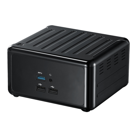
NUC BOX 8265U/8365UE Chapter 2 Product Overview This chapter provides diagrams showing the location of important components of the NUC BOX 8265U/8365UE. 2.1 Front View Description USB 3.0 (Type A) Audio(Mic-in, Line-out) 2 x USB 2.0 (Type A) Power Button... -
Page 12: Rear View
2.2 Rear View Description DC-IN HDMI 2 x USB 3.0 (Type A) 2 x DisplayPort 2 x RJ-45 * There are two LEDs on the LAN port. Please refer to the table below for the LAN port LED indications. ACT/LINK LED SPEED LED LAN Port Activity / Link LED... -
Page 13: Inside View
NUC BOX 8265U/8365UE 2.3 Inside View Description Mini PCIe Slot M.2 Slot SATA 3.0 Connectors SO-DIMM Slot Hard disk drive tray (compatible with 2.5" SATA HDD/SSD) SO-DIMM memory, hard drive and mSATA SSD are not included with this system. -
Page 14: Chapter 3 Hardware Installation
NUC BOX 8265U/8365UE Chapter 3 Hardware Installation This chapter helps you install or remove important components. 3.1 How to Remove the Bottom Case 1. Remove the four screws on the bottom case. 2. Then lift up and remove the bottom panel.. -
Page 15: How To Install The Wifi Module
3.2 How to Install the WiFi Module 1. Locate the WiFi Module slot on the motherboard. 2. Carefully insert the WiFi Module into the slot. 3. Tighten the screw to secure the WiFi Module to the motherboard. -
Page 16: How To Install The M.2 Ssd
NUC BOX 8265U/8365UE 3.3 How to Install the M.2 SSD 1. Locate the M.2 slot on the motherboard. 2. Carefully insert the M.2 SSD into the slot. 3. Tighten the screw to secure the M.2 SSD to the motherboard. -
Page 17: How To Install The 2.5-Inch Hard Drive
3.4 How to Install the 2.5-inch Hard Drive 1. Remove the four screws on the bottom case. Then lift up and remove the bottom panel. 2. Attach the HDD to the hard drive mounting bracket and secure it using the four screws. - Page 18 NUC BOX 8265U/8365UE 3. Attach the HDD assembly to the bottom panel and secure it using the four screws. Connect the SATA Data and Power Cable to the HDD. 4. Then reinstall the bottom panel.
-
Page 19: How To Install The Memory Modules (Ddr4 Low Voltage (1.2V))
3.5 How to Install the Memory Modules (DDR4 Low Voltage (1.2V)) 1. The NUC BOX 8265U/8365UE requires DDR4 SO-DIMM (1.2V). 2. For dual channel configuration, you always need to install identical (the same brand, speed, size and chip-type) DDR4 SO-DIMM pairs. -
Page 20: How To Install The M.2 Heatsink
NUC BOX 8265U/8365UE 3.6 How to Install the M.2 Heatsink 1. Gently insert the M.2 module, along the guiding tabs, into the heatsink bracket. 2. Remove the membranes from both sides of the thermal pad. Then paste the thermal pad onto the M.2 module. -
Page 21: Chapter 4 Motherboard (Nuc Box 8265U)
Chapter 4 Motherboard (NUC BOX 8265U) 4.1 Motherboard Layout PANEL1 RESET HDLED PWRBTN PLED USB2_3_4 USB 3.1: USB3_3 COM1 BIOS AUDIO1 SATA_PWR1 Industrial NUC-8265U SATA3_1 DDR4_B1 (Support DDR4L Only) M2_SEL2 DC_IN1 CLRMOS1 DDR4_A1 (Support DDR4L Only) 1 : M.2 Key-M Socket (M2_1) 2 : M.2 Key-E Socket (M2_2) -
Page 22: Motherboard Specifications
NUC BOX 8265U/8365UE 4.2 Motherboard Specifications Form Dimensions NUC 4.09" x 4.02" (104 x 102mm) Factor ® Intel 8th Gen (Whiskey lake-U) Core™ MCP Processor Processors System I5-8265U QC, 1.6HGz, 15W (NUC-8265U) Chipset PCIe Mini-PCIe mSATA Expansion 1 x Key M (2242/2260/2280 by BRACKET) with... - Page 23 2 x USB 2.0 LVDS/ inverter Serial 1 x COM (RS-232/422/485) Internal SATA 1 x SATA3 ( 6.0Gb/s) Connector Parallel GPIO SATA PWR Output Speaker Header Watchdog Output Interval Timer Input PWR 12V / 96W DC-In (DC Jack) Power ATX Supported Requirements Power On ATX: Press Button to PWR on after Power...
-
Page 24: Jumpers Setup
NUC BOX 8265U/8365UE 4.3 Jumpers Setup The illustration shows how jumpers are setup. When the jumper cap is placed on pins, the jumper is “Short”. If no jumper cap is placed on pins, the jumper is “Open”. The illustration shows a 3-pin jumper whose pin1 and pin2 are “Short”... -
Page 25: Onboard Headers And Connectors
4.4 Onboard Headers and Connectors Onboard headers and connectors are NOT jumpers. Do NOT place jumper caps over these headers and connectors. Placing jumper caps over the headers and connectors will cause permanent damage of the motherboard! SATA3 Connector This Serial ATA3 (SATA3) connector supports SATA data (SATA3_1: see p.16, No. - Page 26 NUC BOX 8265U/8365UE RESET (Reset Switch): Connect to the reset switch on the chassis front panel. Press the reset switch to restart the computer if the computer freezes and fails to perform a normal restart. PLED (System Power LED): Connect to the power status indicator on the chassis front panel. The LED is on when the system is operating.
- Page 27 Back Side: Power Button Header (PWR_BTN1) Fan Connector (FAN1)
-
Page 28: Expansion Slots (M.2 Slots)
NUC BOX 8265U/8365UE 4.5 Expansion Slots (M.2 Slots) There are 2 M.2 slots on this motherboard. M.2 for SSD: Key M (M2_1) (2242/2260/2280 by BRACKET) supports PCIe x4 and SATA3 for SSD. M.2 for Wi-Fi: Key E (M2_2) (2230) supports PCIe x1 and USB 2.0 for Wireless. - Page 29 Chapter 5 Motherboard (NUC BOX 8365UE) 5.1 Motherboard Layout PANEL1 RESET HDLED PWRBTN PLED USB2_3_4 USB 3.1: USB3_3 COM1 BIOS AUDIO1 SATA_PWR1 Industrial NUC-8365U SATA3_1 DDR4_B1 (Support DDR4L Only) M2_SEL2 DC_IN1 CLRMOS1 DDR4_A1 (Support DDR4L Only) 1 : M.2 Key-M Socket (M2_1) 2 : M.2 Key-E Socket (M2_2) 3 : USB2.0 Connector (USB2_3_4) 4 : COM Port Header (RS232/422/485)
- Page 30 NUC BOX 8265U/8365UE 5.2 Motherboard Specifications Form Dimensions NUC 4.09" x 4.02" (104 x 102mm) Factor ® Intel 8th Gen (Whiskey lake-U) Core™ MCP Processor Processors System I5-8365UE QC, 1.6GHz, 15 W (NUC-8365UE) Chipset PCIe Mini-PCIe mSATA Expansion 1 x Key M (2242/2260/2280 by BRACKET) with...
- Page 31 2 x USB 2.0 LVDS/ inverter Serial 1 x COM (RS-232/422/485) Internal SATA 1 x SATA3 ( 6.0Gb/s) Connector Parallel GPIO SATA PWR Output Speaker Header Watchdog Output Timer Interval Input PWR 12V / 96W DC-In (DC Jack) Power ATX Supported Requirements Power On ATX: Press Button to PWR on after Power...
- Page 32 NUC BOX 8265U/8365UE 5.3 Jumpers Setup The illustration shows how jumpers are setup. When the jumper cap is placed on pins, the jumper is “Short”. If no jumper cap is placed on pins, the jumper is “Open”. The illustration shows a 3-pin jumper whose pin1 and pin2 are “Short”...
- Page 33 5.4 Onboard Headers and Connectors Onboard headers and connectors are NOT jumpers. Do NOT place jumper caps over these headers and connectors. Placing jumper caps over the headers and connectors will cause permanent damage of the motherboard! SATA3 Connector This Serial ATA3 (SATA3) connector supports SATA data (SATA3_1: see p.24, No.
- Page 34 NUC BOX 8265U/8365UE RESET (Reset Switch): Connect to the reset switch on the chassis front panel. Press the reset switch to restart the computer if the computer freezes and fails to perform a normal restart. PLED (System Power LED): Connect to the power status indicator on the chassis front panel. The LED is on when the system is operating.
- Page 35 Back Side: Power Button Header (PWR_BTN1) Fan Connector (FAN1)
- Page 36 NUC BOX 8265U/8365UE 5.5 Expansion Slots (M.2 Slots) There are 2 M.2 slots on this motherboard. M.2 for SSD: Key M (M2_1) (2242/2260/2280 by BRACKET) supports PCIe x4 and SATA3 for SSD. M.2 for Wi-Fi: Key E (M2_2) (2230) supports PCIe x1 and USB 2.0 for Wireless.
Need help?
Do you have a question about the NUC BOX 8265U and is the answer not in the manual?
Questions and answers