Table of Contents
Advertisement
Quick Links
Advertisement
Table of Contents

Related Manuals for Quanser qbot


Summary of Contents for Quanser qbot
- Page 1 Specialty Plants User Manual Quanser Qbot...
-
Page 2: Table Of Contents
“Sampling rate is too fast for base rate”............................21 6.6. Trying to start the Qbot model results in the error “Unable to locate the dynamic link library or shared object.”....................21 6.7. The LEDs QBOT POWER and GUMSTIX POWER do not illuminate when the Qbot robot is powered on....................22... - Page 3 Quanser Qbot: User Manual 6.8. Building a model fails with the error “Not enough system resources are available to perform the operation.” The hard disk is full on the Gumstix computer......22 6.9. The Display Image block is not showing any image..........22...
-
Page 4: Introduction
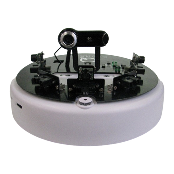
QUARC, Quanser's real-time control software, and the Qbot data acquisition card (DAC). Figure 1: The Quanser Qbot - top view The interface to the QCM is MATLAB Simulink with QUARC. The Qbot is accessible through three different block sets: the Roomba block set to drive the vehicle, the HIL block set to read from sensors and/or write to servo outputs, and finally the OpenCV block set to access the camera. -
Page 5: Prerequisites
The general system description, component nomenclature, specifications, and model parameters are all given in Section 4. Section 5 goes into detail on how to setup the Qbot. Lastly, Section 6 contains a troubleshooting guide. -
Page 6: System Hardware Description
4.1. Qbot Ground Vehicle 4.1.1. The iRobot Create® The Qbot uses an iRobot Create® frame (Figure 3). The Qbot follows the Quanser standard for body frame axes, where the x-axis is in the forward direction, the y-axis is to the left, and Figure 3: Anatomy of the Qbot, showing various components and body axes the z-axis is up. -
Page 7: The Printed Circuit Board (Pcb)
Quanser Qbot: User Manual The Qbot is turned on by pressing the power button (more on Section 5.1). Figure 4 below shows the buttons that are used to operate the iRobot Create®. The Play and Advance but- tons are for built-in demos for the vehicle, and are not necessary for Qbot purposes. -
Page 8: Digital Input/Output Pins (Dio #)
DIO7. 4.1.2.2. Gumstix IR Serial Pins The Qbot provides a TTL serial connection to the Gumstix IR serial port (port number 2). The serial port consists of ground (GND), receive (GUMSTIX IR RXD), transmit (GUM- STIX IR TXD), and power (+3.3V or +5.0V) pins. The serial port is accessed through the QUARC Stream blockset or Stream API. -
Page 9: Sw/Nsw And Int/Ext Jumpers
The Qbot DAC is a data acquisition board, capable of receiving analog inputs and other in- puts (for sonar sensors). It is also capable of writing PWM outputs for possible servo actuat- ors. It is located underneath the black cover of the Qbot, and it is not intended for it to be physically accessed. -
Page 10: Gumstix
The battery fits underneath the Qbot (Figure 8), and can last continuously for about 2 hours after a full charge. The Qbot's power light indicates the power level of the battery. The light is green when the batteries are fresh, then gradually turns red as the battery discharges. -
Page 11: Infrared Sensors
The SHARP 2Y0A02 [5] is a low cost infrared range sensor (20-150 cm). There are five of these sensors included with the Qbot. The sensors are connected to the analog input chan- nels of the Qbot DAC, which can then be read using the HIL Read Write block (Section 5.3). -
Page 12: Sonar Sensors
Objects between 0-inches and 6-inches range as 6-inches. There are three of these sensors included with the Qbot. The sensors are connected to the other input channels of the Qbot DAC, which can then be read using the HIL Read Write block (Section 5.3). -
Page 13: Setting Up The Qbot
5.1. Setting up the Qbot Follow these steps to setup the Quanser Qbot: 1. Insert the battery underneath the Qbot. 2. Press power button shown in Figure 4. This turns on both vehicle and Qbot DAC/Gumstix. 5.2. Establishing Wireless Connection In order to establish wireless communications between the host PC and the Gumstix embed- ded computers, a wireless ad-hoc (peer-to-peer) network is used. - Page 14 5. In the Simulink Library Browser, navigate down QUARC Targets → Devices → Third- Party → iRobot → Roomba → Interfacing. The Roomba Initialize block is required for the Gumstix to communicate with the Qbot. Change the URI to “serial://localhost:1? baud=57600,word=8,parity=none,stop=1” (Local host is 2 by default). Use default send receive bytes.
- Page 15 (Gumstix) rather than simulating the model on the host machine. Table 2 and Table 4 list the block sets supported by the Quanser Qbot, and Table 3 highlights the more important Qbot blocks.
- Page 16 OpenCV library. The image processing block set allows to capture images from a USB (Figure 14) camera, to process it on-line, and to save it to a disk for further analysis. Table 2: Description of the Relevant Qbot Block Sets for the Qbot in QUARC Block Description This block is required to establish a serial connection to a Qbot.
- Page 17 Quanser Qbot: User Manual Figure 12: Interface Block Set Document Number: 830 Revision: 7 Page: 14...
- Page 18 Quanser Qbot: User Manual Figure 13: Application Block Set Figure 14: Image Processing Block Set Document Number: 830 Revision: 7 Page: 15...
- Page 19 The HIL Read Write block must reference this block to determine the board being used. The current version of the Qbot DAC can read from analog channels (for the infrared sensors), and sonar channels. PWM channels are supported for write operations.
-
Page 20: Using The On-Board Camera
Get Iplimage Data block simply takes the image and outputs the image data as a matrix. For the Qbot camera, color images are output as 3-dimensional matrices (3 x ImageWidth x Im- ageHeight) with each pixel represented by a 3-vector of [Blue, Green, Red] values between 0 and 255. -
Page 21: Troubleshooting Guide
Qbot bump sensor inputs are not functioning. 1. Check that the Qbot wheels are retracted fully into the wheel bays. If any wheel is out of its bay, then the Qbot will stop driving for safety reasons. Makes sure to operate the Qbot on a hard, flat surface. -
Page 22: The Model Fails To Build/Connect Or The Quarc Console Does Not Successfully Open
Quanser Qbot: User Manual 3. Turn on the Qbot and open the VAL Read Sensors block in one of the supplied Simulink models. In the VAL Read Sensors parameters under the “Other” channels, select the bump sensors by typing [13000:13002]. Attach a scope or display block to the VAL Read Sensors “Other”... -
Page 23: The Qbot Sensors Are Not Being Read Correctly Or They Are Stuck At Some Constant Value
HIL Write block. Compile and run the model. Verify that the LED leveled DIO7 on the Qbot lid turns on and off when the input to the HIL Write block goes from 1 to 0, respectively. If the DIO7 LED does not turn on, there is a communication failure between the Gumstix and the Qbot computer. -
Page 24: The Simulink Model Appears To Run Slowly (I.e., The Simulation Time Runs Slower Than Actual Time), Or The Console Displays The Message "Sampling Rate Is Too Fast For Base Rate
“Unable to locate the dynamic link library or shared object.” 1. This error indicates that the Qbot driver is not found on the target. Make sure that the model target type is set to Linux Verdex by navigating to the QUARC menu QUARC\Op- tions\Real-Time Workshop pane and changing the System target file to quarc_linux_ver- dex.tlc. -
Page 25: The Leds Qbot Power And Gumstix Power Do Not Illuminate When The Qbot Robot Is Powered On
2. If the jumpers are securely in place and the power LEDs remain off when the iRobot Cre- ate is on, turn off the robot, open the Qbot lid by removing the four lid screws shown in Figure 16, and verify that the DB-25 cable to the robot is securely connected. Replace the lid and try to power on the Qbot. - Page 26 Quanser Qbot: User Manual If the image is output as matrix data remove the Vision Get Iplimage Data block. 2. Check that the Image Convert block is set to convert the source image format BGR8 to MATLAB RGB. 3. Set the Display Image sample time to 0.5 seconds.
Need help?
Do you have a question about the qbot and is the answer not in the manual?
Questions and answers