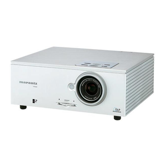
Marantz vp8600 Service Manual
Hide thumbs
Also See for vp8600:
- User manual (32 pages) ,
- Throw distance manual (2 pages) ,
- Manual (2 pages)
Advertisement
Quick Links
Service
Manual
SECTION
1. TECHNICAL SPEC I FI CA TIONS ........................................................................................... 1
2. SERVICE MODE ................................................................................................................... 3
3. DISASSEMBLE PROCEDURE ............................................................................................. 4
4. WIRING DIAGRAM ............................................................................................................. 15
5. BLOCK DIAGRAM .............................................................................................................. 17
6. PWB LOCATION ................................................................................................................. 19
7. EXPLODED VIEW AND PARTS LIST ................................................................................. 21
Please use this service manual with referring to the user guide ( D.F.U. ) without fail.
TABLE OF CONTENTS
VP8600
VP8600 /
F S/U1S
DLP Projector
PAGE
Part no. 90M20AV855010
First Issue 2005.12
MZ
Advertisement

Summary of Contents for Marantz vp8600
-
Page 1: Table Of Contents
Service VP8600 / F S/U1S Manual DLP Projector TABLE OF CONTENTS SECTION PAGE 1. TECHNICAL SPEC I FI CA TIONS ................... 1 2. SERVICE MODE ........................3 3. DISASSEMBLE PROCEDURE ..................... 4 4. WIRING DIAGRAM ......................15 5. BLOCK DIAGRAM ......................17 6. - Page 2 MARANTZ Parts for your equipment are generally available to our National Marantz Subsidiary or Agent. ORDERING PARTS : Parts can be ordered either by mail or by Fax.. In both cases, the correct part number has to be specifi ed.
-
Page 3: Technical Specifications
1. TECHNICAL SPECIFICATIONS ❖ ❖ Optical characteristics 光学特性 Panel 0.8 inch 16:9 パネル 0.8インチ16:9 1280 x 720 pixels 921,600画素 (1280×720) Digital Micromirror Device Digital Micromirror Device ( DMD) Lamp 200W AC ランプ 200W AC Lens f: 32.5 to 44.0mm レンズ f:24.1∼32.3mm F: F2.5 F:F2.2−2.5... - Page 4 Replace Lamp Module See "Step 2--Remove the Lamp Module (LU8600VP)" in "3. DISASSEMBLE PROCEDURE" section. • Service Spare Parts no. (Lamp module LU8600VP) : 90M-ZK000560R ランプの交換 "3. DISASSEMBLE PROCEDURE" の "Step 2--Remove the Lamp Module (LU8600VP)" を参照して ください。 • 交換ランプ LU8600VP) : 90M-ZK000560R サービス...
-
Page 5: Service Mode
2. SERVICE MODE • How to enter the Service Mode • サービスモードの入り方 Operate by using [Remote controller RC8600VP]. The unit is セットは無信号状態で、リモコン RC8600VP にて操作を行い no-signal conditions. ます。 主電源スイッチを押しセットの電源を入れます。 1. Press the Main power switch to turn on the unit. ) → RIGHT( ) →... -
Page 6: Disassemble Procedure
3. DISASSEMBLE PROCEDURE... -
Page 17: Wiring Diagram
4. WIRING DIAGRAM 5 DLP OPTICAL ENGINE ASSY RS-232C 9 pin IRCN100 RGB(D-sub) 15 pin CN100 1 Main PWB IRCN101 DVI-D CN200 IRCN102 TRIGGER1 Screen(trigger 12V) CN902 IRCN 103 TRIGGER2 AS(trigger 12V) CN910 Lamp fan Left fan Power fan DMD fan Engine fan Right fan 4 DMD PWB CN1104... -
Page 18: Block Diagram
5. BLOCK DIAGRAM U1102 FAN4 16X4M Composite video UV207 SRAM W83782 MASTER IIC VIDEO THERMAL FAN5 SAA7118 16BITS U700 U201 16BITS YUV U200 CONTROL FLASH VIDEO 24BITS RGB DATA FAN6 S video DECODER U1008 U1100 30 BITS FLASH 3RCA/5RCA ADDRESS FAN1 W83782 HV SYNC... -
Page 19: Pwb Location
6. PWB LOCATION 6. RCA PWB ASSY 4. DMD PWB ASSY 18. C/W INDEX PWB ASSY 1. MAIN PWB ASSY 16. LED PWB ASSY 2. POWER PWB ASSY 17. IR PWB ASSY 15. BALLAST PWB ASSY 3. LVPS PWB ASSY... -
Page 20: Exploded View And Parts List
7. EXPLODED VIEW AND PARTS LIST DLP OPTICAL ENGINE ASSY... - Page 21 CONN ADP TV PLUG DVI MALE/HDMI FEMALE 3072284633 37 F S LABEL LABEL MODEL NAME JAPAN 320281500X 37 /U1S LABEL LABEL MODEL NAME WW 320281460X NOTE : "nsp" PART IS LISTED FOR REFERENCE ONLY, MARANTZ WILL NOT SUPPLY THESE PARTS.
- Page 22 PACKING...


