Table of Contents
Advertisement
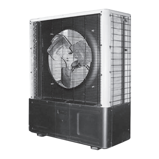
S1C/S1H SINGLE-ZONE & S2C DUAL-ZONE
SIDE DISCHARGE DUCTLESS SPLIT SYSTEM
CONDENSING UNITS
STRAIGHT COOL/HEAT PUMP S1C/S1H
Nominal Circuit Capacities S1C/S1H:
9,000, 12,000, 18,000, 24,000 Btuh and
S1C 30-36 Btuh
COOLING ONLY S2C
Nominal Circuit Capacities:
9,000-12,000 Btuh
S1C/S1H
S2C
Enviromaster International LLC
5780 Success Dr.
An ISO 9001-2000 Certified Company
Rome, NY 13440
www.enviromaster.com
P/N# 240005897 Rev. 1.2 [05/06]
Advertisement
Table of Contents

Related Manuals for EMI S1C


Summary of Contents for EMI S1C
-
Page 1: Condensing Units
S1C/S1H SINGLE-ZONE & S2C DUAL-ZONE SIDE DISCHARGE DUCTLESS SPLIT SYSTEM CONDENSING UNITS STRAIGHT COOL/HEAT PUMP S1C/S1H Nominal Circuit Capacities S1C/S1H: 9,000, 12,000, 18,000, 24,000 Btuh and S1C 30-36 Btuh COOLING ONLY S2C Nominal Circuit Capacities: 9,000-12,000 Btuh S1C/S1H Enviromaster International LLC 5780 Success Dr. -
Page 2: Safety Instructions
P/N 240005897, Rev. 1.2 [05/06] This manual is intended as an aid to a qualified service personnel for proper installation, operation, and maintenance of EMI AmericaSeries high efficiency condensing units. Carefully read these instructions before attempting installation or operation. Failure to follow these instructions may result in improper installation, operation, service, or maintenance, possibly resulting in fire, electrical shock, property damage, personal... - Page 3 9,000-12,000 Btuh units are equipped • Low Ambient controls for operation down with a Duratec Performance Package that to 32º F , specify this option for S1C or includes an oversized suction accumula- S2C systems (standard on S1H’s) that tor with surge baffles and enhanced oil...
-
Page 4: Installation Instructions
ITEMS FOR CONSIDERATION INSTALLATION INSTRUCTIONS • Locate the unit as close to the indoor UNIT MOUNTING INSTRUCTIONS S1C is shown section as possible. (See Tubing Specifications chart on pape 7.) Side discharge unit allows for per- manent mounting through the feet. This is •... -
Page 5: Electrical Wiring
INSTALLATION INSTRUCTIONS ELECTRICAL WIRING UNIT MOUNTING INSTRUCTIONS Continued 1. All electrical wiring must be run accord- ing to NEC and local codes. Compressor Accumulator Capacitor 2. Refer to the unit rating plate for voltage, minimum circuit ampacity and over cur- rent protection requirements. - Page 6 INSTALLATION INSTRUCTIONS 8. Check wiring diagram for the required c. Slide the side panel out to access the number of low voltage wires to be run high/low electrical connections and wire diagram. between indoor and outdoor sections. Shown High Volt Low Volt Low Volt Connection Plastic Edge Guards...
-
Page 7: Refrigerant Piping
INSTALLATION INSTRUCTIONS ELECTRICAL WIRING REFRIGERANT PIPING Continued INTERCONNECTING TUBING SPECIFICATIONS MAX. Max. Liquid Suction Model Length Lift Line O.D. Line O.D. 100’ 35’ 1/4" 1/2" 100’ 35’ 1/4" 1/2" 100’ 35’ 3/8" 5/8" 100’ 35’ 3/8" 3/4" 100’ 35’ 3/8" 3/4"... - Page 8 INSTALLATION INSTRUCTIONS P-TRAP INSTALLATION • A P-trap is recommended when the suc- ricated trap may be purchased from a wholesaler or distributor however the trap tion riser is equal to or greater than 20 should be shallow as the (3) elbow con- feet in height.
- Page 9 INSTALLATION INSTRUCTIONS REFRIGERANT PIPING Continued 1. Clean the ends of tubing and insert into fi ttings. Shown 5. Attach manifold set. Shown Manifold Vaccum Pump Micron Gage 2. Protect the valves by wrapping with a wet rag "heat sink" before brazing. Shown Manifold Setup For Evacuation Shown...
-
Page 10: Refrigerant Processing
1. To find the charge adjustment and system charge for any evaporator and tubing length: Line Adjustment = (Line Charge/FT) x Line Length System Total = Factory Charge + Line Adjustment 2. Round to the nearest ounce and allow for gauges and hoses. S1C REFRIGERANT CHARGE TABLE CONDENSER EVAPORATOR PAIRING LINE CHG/FT... - Page 11 INSTALLATION INSTRUCTIONS REFRIGERANT PROCESSING Continued S2C REFRIGERANT CHARGE TABLE CONDENSER EVAPORATOR PAIRING LINE CHG/FT FACTORY CHARGE .25 oz. 28 oz./ 28 oz. S2CA99 WLHA09 .25 oz. 33 oz./ 33 oz. S2CA22 WLHA12 .25 oz. 28 oz./ 33 oz. S2CA92 WLHA09+WLHA12 .25 oz.
-
Page 12: Single Zone Operation Charts
SINGLE ZONE OPERATION CHARTS Cooling Cycle Cooling Cycle Models S1C2, S1H2 Models S1C9, S1H9 with EMI’s-WLH12 or CAC12 (���� ����� with EMI’s-WLH09 or CAC12 (���� ����� ��� ��� ���� ����� ���� ���� ����� ���� �������� �������� ��� �������� �������� ���... - Page 13 SINGLE ZONE OPERATION CHARTS Cooling Cycle Cooling Cycle Models S1C4, S1H4 Models S1C8, S1H8 with EMI’s-WLH24 or CAC24 (���� ����� with EMI’s-WLH24 or CAC24 (���� ����� ��� ��� ���� ����� ���� ���� ����� ���� �������� �������� ��� �������� �������� ���...
- Page 14 SINGLE ZONE OPERATION CHARTS Cooling Cycle Cooling Cycle Models S1C3 Models S1C3 with EMI’s-CAC36 (���� ����� with EMI’s-WLC30 (���� ����� ��� ��� ���� ����� ���� ���� ����� ���� �������� �������� ��� �������� �������� ��� ��� ��� ��� ��� ��� ���...
- Page 15 SINGLE ZONE OPERATION CHARTS Cooling Cycle Cooling Cycle Models S1C6 Models S1C6 with EMI’s-CAC36 (���� ����� with EMI’s-WLC36 (���� ����� ��� ��� ���� ����� ���� ���� ����� ���� �������� �������� ��� �������� �������� ��� ��� ��� ��� ��� ��� ���...
- Page 16 SINGLE ZONE HEAT PUMP OPERATION CHARTS Heat Cycle Heat Cycle Models S1H2 Models S1H9 with EMI’s-WLH12 (���� ����� with EMI’s-WLH09 (���� ����� ���� ����� ���� ��� ��� ���� ����� ���� ��� ��� ��� ��� ��� ��� ��� ��� ��� ���...
- Page 17 SINGLE ZONE HEAT PUMP OPERATION CHARTS Heat Cycle Heat Cycle Models S1H8 Models S1H4 with EMI’s-WLH24 (���� ����� with EMI’s-WLH24 (���� ����� ���� ����� ���� ���� ����� ���� ��� ��� ��� ��� ��� ��� ��� ��� ��� ��� ��� ���...
- Page 18 DUAL ZONE OPERATION CHARTS Cooling Cycle Cooling Cycle Models S2C99 Models S2C22 with EMI’s-WLC09 or CAC12 (���� ����� with EMI’s-WLC12 or CAC12 (���� ����� ��� ��� ���� ����� ���� ���� ����� ���� �������� �������� ��� �������� �������� ��� ��� ���...
- Page 19 Record results on Test Unit Data Sheet on page 25. OPERATION AND MAINTENANCE The S1C/H and S2C outdoor sections This unit is equipped with a perma- are the compressor bearing units of the nently lubricated motor. Although oiling is system.
- Page 20 (R & Y) will energize. When the indoor Note: For remote wall mounted ther- control is satisfied and the room temper- mostat operation be sure to select EMI ature rises above the set temperature, p/n 240004180 or a suitable 24V, two the compressor and fan will de-energize.
- Page 21 DFT TST R and DF2 www.enviromaster.com Side Discharge Condensers...
- Page 22 S1C/S1H SPECIFICATIONS AND DIMENSIONS NOTE: All EMI products are subject to ongoing development. Design and specifications may change without notice. PHYSICAL DIMENSIONS Model Size S1CA/S1HA9 24" 15" 36" S1CA/S1HA2 24" 15" 36" S1CA/S1HA8 32" 15" 36" S1CA/S1HA4 32" 15" 40"...
- Page 23 S1C/S1H SPECIFICATIONS AND DIMENSIONS NOTE: All EMI products are subject to ongoing development. Design and specifications may change without notice. System Performance Data: Matched With EMI AmericaSeries Indoor Units HEAT PUMPS SYSTEM OPTIONS WITH WALL UNITS Cooling Heating Condenser Wall Unit...
- Page 24 S2C SPECIFICATIONS AND DIMENSIONS 1/2” Diameter Lag Holes SOUND DATA PHYSICAL DIMENSIONS Model Size Model Size 32" 15" 36" 22, 92 32" 15" 40" Side Discharge Condensers www.enviromaster.com...
- Page 25 TEST UNIT PERFORMANCE DATA SHEET The Test Unit Performance Data sheet this information ready when calling. Make below is provided for use by a qualified sure to include the Model Number, Serial service professional in the event that there Number, Date of Installation. is a problem with the unit.
-
Page 26: Emi's Product Line
EMI’S PRODUCT LINE EVAPORATORS WLC/WLH High Wall Evaporator Cassette Evaporator CONDENSERS S1C & S1H Single Zone Side Discharge T2C, T3C & T4C 2, 3 & 4 Zone Top Discharge Dual Zone Side Discharge Side Discharge Side Discharge Condensers Side Discharge Condensers... - Page 27 fitness for a particular purpose and all other warranties express or implied. The remedies provided for in this warranty are exclusive and shall constitute the only liabilities on the part of EMI including any statements made by any individual which shall be of no effect. FOR SERVICE OR REPAIR:...
Need help?
Do you have a question about the S1C and is the answer not in the manual?
Questions and answers