Table of Contents
Advertisement
ECR International Inc
2201 Dwyer Ave.
Utica, NY 13501
www.enviromaster.com
An ISO 9001-2008 Certified Company
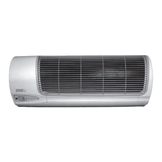
WLCG/WLHG
High-Efficiency Ductless Split System High-Wall Air Handlers
Straight cool / Heat pump nominal capacities
WLHG09
WLHG12
9,000
12,000
2.6
3.5
Straight cooling only
WLCG30
28,200
8.3
Installation, Operation and
Maintenance Manual
WLCG/WLHG
WLHG24
18,000
23,800
5.3
7.0
WLCG36
33,600
9.8
P/N 240008111, Rev. G [06/18/10]
Units
Btuh
kW
Units
Btuh
kW
Advertisement
Table of Contents

Related Manuals for EMI WLHG09


Summary of Contents for EMI WLHG09
- Page 1 WLCG/WLHG High-Efficiency Ductless Split System High-Wall Air Handlers Straight cool / Heat pump nominal capacities WLHG09 WLHG12 WLHG24 Units 9,000 12,000 18,000 23,800 Btuh Straight cooling only WLCG30 WLCG36 Units 33,600 28,200 Btuh Installation, Operation and Maintenance Manual WLCG/WLHG ECR International Inc 2201 Dwyer Ave.
-
Page 2: Table Of Contents
For a local representative listing, visit NOTICE our web site: The EMI series high efficiency air www.enviromaster.com handler is backed by EMI and ECR For further assistance call: International is tested, rated, and certi- fied in accordance with AHRI Standard 1-800-228-9364 210/240-2008 and UL-1995. -
Page 3: Read Before Proceeding
Inspect all parts for damage prior to installation and start-up. The EMI se- EMI series high efficiency air handler. ries high efficiency air handler must be Read these instructions thoroughly and... -
Page 4: Verify Unit Before Installing
Room air sampling — Selectable time T3HG, or T4CG/T4HG. intervals ensure the fan will cycle on peri- • All EMI air handlers are backed by ECR odically, in Auto Fan Mode to help elimi- International Inc. and are tested, rated, nate room temperature stratification. -
Page 5: Optional Equipment
WLCG/WLHG High-Wall Air Handlers • Installation, Operation and Maintenance Manual • Verify Unit Before Installing (continued) • Minimum on time for heating and cooling • Easy access to pipe chase area from cabi- Helps eliminate room temperature droop net bottom allows piping connections and and system short cycling. -
Page 6: Piston/Orifice Replacement (When Required)
WLCG/WLHG High-Wall Air Handlers • Installation, Operation and Maintenance Manual • Piston/Orifice Replacement (when required) NOTICE — WLHG24 ONLY — The factory-installed piston/orifice must be replaced on Piston/ Orifice replacement . All other applications are Air-Handler / Condenser combitnations noted in table below to use the factory-installed orifice. -
Page 7: Mounting The Unit
WLCG/WLHG High-Wall Air Handlers • Installation, Operation and Maintenance Manual • Mounting the Unit smooth surface such as Sheetrock® wallboard Before installing, consider: or similar material. If mounting to a masonry • Determine the best location for mounting block wall, there should be a smooth bar- the unit for room air circulation. - Page 8 WLCG/WLHG High-Wall Air Handlers • Installation, Operation and Maintenance Manual • Mounting the Unit (continued) Unit Mounting Instructions Wall hanging bracket Figure 4 After determining the best location for the unit, use the cardboard template provided in the packaging (Figure 3, Page 7).
-
Page 9: Electrical Wiring
WLCG/WLHG High-Wall Air Handlers • Installation, Operation and Maintenance Manual • Electrical Wiring NOTICE Before removing end cap Figure 6 All electrical wiring must be run accord- Helpful Tip: ing to NEC and local codes. Prior to remov- ing the end cap and Site preparation for wiring bottom... - Page 10 WLCG/WLHG High-Wall Air Handlers • Installation, Operation and Maintenance Manual • Electrical Wiring (continued) Connect wiring Wiring diagram location Figure 9 To access High and Low volt wiring re- move the screw on the front of the control box. (Figure 9, pg. 10) High voltage electrical wiring Refer to the wiring diagram to connect the power wire to Black L1 and the other wire...
- Page 11 WLCG/WLHG High-Wall Air Handlers • Installation, Operation and Maintenance Manual • Electrical Wiring (continued) Units with or without heat Unit-mounted controls — Figure 11 cooling only NOTICE All low voltage interconnect wiring must be at least 18 AWG. Cooling-only Cooling only units utilize two low volt in- terconnecting wires between the indoor and outdoor units.
- Page 12 WLCG/WLHG High-Wall Air Handlers • Installation, Operation and Maintenance Manual • Electrical Wiring (continued) Wall thermostat controls Wall-mounted thermostat Figure 13 For remote wall mounted thermostat layout see - configuration — (Figure 13, pg 12) cooling only NOTICE All low voltage interconnect wiring must be at least 18 AWG.
- Page 13 Heat pump operation requires the connection of the “O” (orange) terminal from the outdoor unit to the thermostat. The reversing valve is energized in the cool- ing mode for EMI models S1HG heat pump condensers. NOTICE Wall-mounted thermostat Figure 15...
-
Page 14: Refrigerant Piping
WLCG/WLHG High-Wall Air Handlers • Installation, Operation and Maintenance Manual • Refrigerant Piping Removing bottom panel Figure 16 CAUTION • Avoid piping on wet and rainy days. • Use only clean, refrigeration-grade copper tubing. • Use tubing benders to guard against kinking. - Page 15 WLCG/WLHG High-Wall Air Handlers • Installation, Operation and Maintenance Manual • Refrigerant Piping (continued) NOTICE Clean ends of tubing Figure 18 The WLCG/WLHG is equipped with a Flo Rater piston expansion device or TXV. Connections are sweat type. Line sizing Size lines per (Table 7, Page 43).
- Page 16 WLCG/WLHG High-Wall Air Handlers • Installation, Operation and Maintenance Manual • Refrigerant Piping (continued) Refrigerant processing Manifold set connections at unit Figure 20 Attach manifold set (Figure 20 page 16). Evacuate line to 500 microns or less to ensure all moisture has been removed and there are no leaks.
-
Page 17: Refrigerant Processing
Table 2 Wall Unit Line charge Factory Condenser Top discharge, Multi-zone pairing per foot charge .25 oz./ft 39.5 oz. S1CG9 WLHG09 (23 g/m) (1119 g) Wall Unit Line charge Factory Circuit capacity per foot charge Paring .25 oz./ft 33.75 oz. -
Page 18: Reassemble The Wlcg/Wlhg Cabinet
WLCG/WLHG High-Wall Air Handlers • Installation, Operation and Maintenance Manual • Reassemble the WLCG/WLHG Cabinet Replace bottom panel Figure 23 CAUTION Verify the system is leak-free and all pip- ing has been properly installed before reassembling the cabinet. Reassemble the cabinet Figure 23, Page 18 Replace the bottom panel. -
Page 19: Initial Start-Up
For operating details, see informa- to warm the room before testing the tion beginning on page 25. unit’s cooling abilities. The EMI Series controller can operate the unit in cooling, heating (when equipped) or auto Before starting the unit changeover mode. Setpoint temperature can... -
Page 20: Wlcg/Wlhg Controller Overview
WLCG/WLHG High-Wall Air Handlers • Installation, Operation and Maintenance Manual • WLCG/WLHG Controller Overview Figure 26 Ductless Series unit-mounted controller — chassis-mounted keypad/display Press to turn on or off. ON/OFF Press to change operating mode — toggles between Cool, Heat, Auto changeover, MODE Dry or Fan modes. - Page 21 WLCG/WLHG High-Wall Air Handlers • Installation, Operation and Maintenance Manual • WLCG/WLHG Controller Overview (continued) Figure 27 WLCG/WLHG controller — infrared remote control — optional only Press to turn unit on or off. POWER Use to increase (+) or decrease (-) the setpoint temperature.
-
Page 22: Setting The Controller
WLCG/WLHG High-Wall Air Handlers • Installation, Operation and Maintenance Manual • Setting the Controller Configuration settings for WLCG/WLHG Figure 28 (available only using unit-mounted keypad) Possible Value Factory Setting Item Display Overview (flashing) Settings To access: While in OFF mode, press MODE and PROG together for 10 seconds, repeat to exit; automatically exits after 20 seconds idle Select temperature scale for display and operating settings. - Page 23 WLCG/WLHG High-Wall Air Handlers • Installation, Operation and Maintenance Manual • Setting the Controller (continued) Setup options for WLCG/WLHG high-wall air handlers Figure 29 Possible Value Factory Item Display Overview (flashing) Settings The louver is closed when the fan is off. 01, 02, If set to AUTO, the louver oscillates through all positions during fan 03, 04,...
- Page 24 WLCG/WLHG High-Wall Air Handlers • Installation, Operation and Maintenance Manual • Setting the Controller (continued) Table 3 Programming schedule (when using 7-day programming) To copy the settings from any day to the entire week: 1) Select the day to be copied. 2) Simultaneously press the “FAn”...
-
Page 25: Unit-Mounted Controller Operation
WLCG/WLHG High-Wall Air Handlers • Installation, Operation and Maintenance Manual • Unit-Mounted Controller Operation FAN operation NOTICE When power is first applied to the con- The indoor unit utilizes a two-speed motor trol or after a power outage there is a with three operational fan modes. - Page 26 WLCG/WLHG High-Wall Air Handlers • Installation, Operation and Maintenance Manual • Unit-Mounted Controller Operation (continued) Room air sampling NOTICE Once the compressor is switched off, If the room air sampling feature has been or after a power outage, there is a three- enabled in configuration (see Figure 28, minute delay before the compressor will Page 22.), then after the fan has been off for...
-
Page 27: Dry Mode
WLCG/WLHG High-Wall Air Handlers • Installation, Operation and Maintenance Manual • Unit-Mounted Controller Operation (continued) (Heat source ON, heat pump ON). See (Fig- • The compressor will not re-start until a ure 28, Page 22). three minute delay has elapsed. •... -
Page 28: Auto Changeover Operation
WLCG/WLHG High-Wall Air Handlers • Installation, Operation and Maintenance Manual • Unit-Mounted Controller Operation (continued) continue to boost the room temperature • The compressor will start and the unit will back up to setpoint temperature. run cooling operation as described under Cool mode, page 26. -
Page 29: Wall Thermostat Operation
When power is first applied to the con- When selecting a thermostat other than one trol or after a power outage there is a offered by EMI, it is important to choose a three minute delay before the compres- 24V thermostat that matches your applica- sor or electric heat will energize. - Page 30 WLCG/WLHG High-Wall Air Handlers • Installation, Operation and Maintenance Manual • Wall Thermostat Operation (continued) FAN operation COOLING operation The indoor unit utilizes a two-speed motor. The wall thermostat will control the call for cooling operation (on or off) through the low •...
- Page 31 WLCG/WLHG High-Wall Air Handlers • Installation, Operation and Maintenance Manual • Wall Thermostat Operation (continued) ELECTRIC HEAT operation Optional HEAT PUMP WITH ELECTRIC HEAT (Two-stage heating) For wall thermostat operation with electric heat the control must be configured properly For wall thermostat operation for two stage (Remote Thermostat ON, heat source ON).
-
Page 32: Controller Features
WLCG/WLHG High-Wall Air Handlers • Installation, Operation and Maintenance Manual • Controller Features • If Intermittent is selected, the backlight Short Cycle Protection (ASCT) will remain for 10 seconds after the The electronic control incorporates an anti- push of any button while the control is short-cycle timer (ASCT) feature designed in the On mode or after the push of the to protect the compressor from short cycling. -
Page 33: Controller Fault Conditions
WLCG/WLHG High-Wall Air Handlers • Installation, Operation and Maintenance Manual • Controller Fault Conditions Table 4 Unit-mounted controller fault indications Code Fault condition Description Room air sensor fault If the room air sensor is disconnected, dam- aged or malfunctions the LCD display will flash error code E01 to signify that a fault has occurred. -
Page 34: Maintenance
Failure to do so could result in injury or electric shock. Clean the filter EMI units are designed and constructed for reliability and long life with minimal mainte- nance. To insure peak operating efficiency, clean the filter as needed, following the pro- Removing the filter cedure given here. - Page 35 WLCG/WLHG High-Wall Air Handlers • Installation, Operation and Maintenance Manual • Maintenance (continued) Replace filters, clips and front grille before Replace filters and grille before Figure 33 operating the unit (Figure 33, Page 35). operating the unit WARNING DO NOT operate the unit without the filter and front grille in place.
-
Page 36: Troubleshooting
Please have the full model and serial number available prior to calling. Wiring requirements EMI Series air handlers are designed to oper- Figure 38 Wiring connections — straight ate with EMI Series condensers. cool applications with wall •... - Page 37 Power supply check When troubleshooting any EMI product, it is important to first check the rating plate for proper field voltage and breaker size. Then use a voltmeter to check the incoming power supply to verify that it agrees with the rating plate.
- Page 38 WLCG/WLHG High-Wall Air Handlers • Installation, Operation and Maintenance Manual • Troubleshooting (continued) heater assembly will interrupt power to the Low voltage controls — heater should an overheat condition occur. cooling-only units Each electric heat assembly is also equipped Cooling-only units utilize low volt intercon- with a one-time fuse link.
- Page 39 Units with condensate pumps The air handler or wall thermostat will cycle EMI Air Handlers are available with an op- the condenser through the yellow (Y) wire as tional condensate pump. Condensate pumps it does in cooling, however the reversing valve are recommended when it is not possible to will not be energized.
-
Page 40: Frequently Asked Questions
Frequently Asked Questions Q: The system has just been installed using Q: The display on the indoor unit is blank. an EMI indoor unit and a non-EMI con- What should I do? denser. There is no display and the unit will A: Check the power supply (see “Power... - Page 41 WLCG/WLHG High-Wall Air Handlers • Installation, Operation and Maintenance Manual • Frequently Asked Questions (continued) Q: What causes my indoor unit to freeze- Q: I lost my infrared remote. How do I oper- ate the unit? A: Air handler freeze up is usually the symp- A: All infrared remote functions can be ac- tom of another problem.
-
Page 42: Specifications And Dimensions
(mm) in (mm) in (mm) (kg) in (mm) in (mm) WLHG09 9 7/8” (251) 15 ¼” (387) 38 ½” (978) 24” (610) 26 ½” (673) 58.0 (26.4) WLHG12 9 7/8” (251) 15 ¼” (387) 38 ½” (978) 24” (610) 26 ½”... - Page 43 WLCG/WLHG High-Wall Air Handlers • Installation, Operation and Maintenance Manual • Specifications and Dimensions (continued) Table 5 WLCG/WLHG electrical specifications HEATER TOTAL HACR MODEL VOLTS/HZ/PH AMPS M.C.A. K.W. AMPS VOLT BRKR 115/60/1 0.64 0.02 – – 0.64 09–12 208/230/60/1 0.34 0.02 –...
-
Page 44: Wlcg/Wlhg System Options
0.71 11.9 R410A S2HG99 (2) WLHG09 18,000 18,000 13.0 0.73 12.1 R410A S2HG22 (2)WLHG12 24,000 24,000 13.0 0.68 12.0 R410A S2HG92 (1) WLHG09+ (1) WLHG12 21,000 21,000 13.0 0.70 12.0 R410A Comfort where it counts P/N 240008111, Rev. G [06/18/10]... - Page 45 T3HG2220 (3)WLHG12 36,000 31,200 13.0 0.72 11.5 410A T3HG2240 (2) WLHG12, WLHG24 47,500 42,500 13.0 0.71 11.5 410A T3HG9920 (2) WLHG09, WLHG12 30,000 27,400 13.0 0.76 11.5 410A T3HG9980 (2) WLHG09, WLHG24 36,000 33,500 13.0 0.76 11.5 410A T3HG9990 (3)WLHG09...
-
Page 46: Test Unit Performance Data Sheet
WLCG/WLHG High-Wall Air Handlers • Installation, Operation and Maintenance Manual • Test Unit Performance Data Sheet NOTICE The Test Unit Performance Data sheet is provided Have this information ready when calling. Make sure to include the Model Number, Serial Number, and for use by a qualified service professional in the event Date of installation. -
Page 47: Emi's Product Line
WLCG/WLHG High-Wall Air Handlers • Installation, Operation and Maintenance Manual • EMI’s Product Line Indoor Units WLCG/WLHG CACG/CAHG High Wall Air Handler Cassette Air Handler UnCG/UnHG Universal Floor or Ceiling Air Handler Outdoor Units S2CG/S2HG Dual Zone T2CG/T2HG, T3CG/ Side Discharge... - Page 48 Phone: 1-800-228-9364 2201 Dwyer Ave. Fax: 1-800-232-9364 Utica, NY 13501...
Need help?
Do you have a question about the WLHG09 and is the answer not in the manual?
Questions and answers