Midway Arctic Thunder Manual
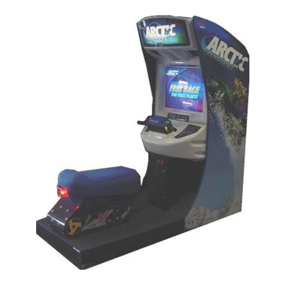
27” dedicated video game
Hide thumbs
Also See for Arctic Thunder:
- Connection instructions (6 pages) ,
- Operation manual (10 pages)
Table of Contents
Advertisement
Game Operations
Manual for 27"
Dedicated Video
Game
Manual Includes
Operation &Adjustments * Parts Information ' Wiring Diagrams
The manufacturer intends that this game is to be operated for amusement
any federal. state or local law or regulation of !he Untted
operators of this game are responsible
turer's factory settings for this game may reoui:e
specific jurisdlctlon.
It is the operator's responsiQty to determlne
to make the appropriate aujustments
3 4 0 1 NORT-! CALIFORV:& A
States or any foreign
for its oxratIon I ! ? accordance WI : P
adjustment in order to ccmpiy
whether adjustments are necessary ald, if they are
G
A M U S E M E N T
A M E S
V E N U E
NOVEMBER
Testing & Problem Diagnosis
l
only and not in contravention
such laws and regulations.
with laws applicable in an operator's
.
6 0 6 1 8 U S A
2000
16-40089-l 01
devices. A:,
The manufac-
Advertisement
Table of Contents
Troubleshooting

Related Manuals for Midway Arctic Thunder


Summary of Contents for Midway Arctic Thunder
- Page 1 NOVEMBER 2000 16-40089-l 01 Game Operations Manual for 27” Dedicated Video Game Manual Includes Operation &Adjustments * Parts Information ’ Wiring Diagrams Testing & Problem Diagnosis The manufacturer intends that this game is to be operated for amusement only and not in contravention any federal.
- Page 2 MIDWAY AMUSEMENT GAMES, I.,LC 3401 N. CALIFORNIA AVE. CHICAGO, n, 60618 U.S.A. WE, HEREBY DECLARE UNDER SOLE RESPONSIBILITY THAT TO WHICH THIS DECLA!GTIOh RELATES IS IN CONFORMITY WITH THE FOLLOWING EUROPEAN PRODUCT SAFETY DIRECTIVES: CTROMAGNETIC COMPATIBILITY DIRECTIVE AND AMENDMENTS 91/C162/08, ELECTRICAL EOUIPMENT DESIGNED FOR USE J+‘ITIiIIN...
- Page 3 in c.rder to s e! the hub switches for iNk’ (IInk) over! actlv,ti the nub so that the indicaror lights are vlslble and cable jacks are accessible Connect rhe AC. adap:ei for :he hub ald all line cords to AC power CAUTION or disconnect any cable to the game electronics or hub wlth the powtr turned enters ATTRACT MODE if nc errors are found...
- Page 4 P E R A T I O N S...
- Page 5 SAFETY INSTRUCTIONS The following safety instructions apply to operators and seduce personnel. Read these instructrons before servicing or prepar’ng the Vloeo Game Machine !‘VGM) fo- play. Other saiety instructions appea- through- out t h 1. s manual. DEFINITIONS OF SAFETY TERMS DANGER Indica:es an imminent hazard.
- Page 6 1 OPERATION CAUTION: AlTACH CONNECTORS PROPERLY. Be sure board connectors mate properly. if connectors do not slip cn easily. do not force them. A reversed connector may damage the VGM and void the warranty. Connector keys only allow a connector to frt one set of prns on board CAUTION: USE CARE WHEN SHIPFING HARD DISKS.
-
Page 7: Product Specifications
1 OPEPrZTICFd PRODUCT SPECIFICATIONS Operating Requirements Foreign 230VAC & 50Hz 2.1 Amps J a p a n C a b i n e t s t a t i s t i c s Sit-On Dedl c a:ed Video Gan:? Main Cabi n et cm 1 Height 78”... - Page 8 1 OPEW-ION SET-UP from shrpprng contarners and set them aside. Remove all Inspect exterior of the marn cabinet and sea? pedestal for any damage. WARNING Cabinet top heavy. Do not push agarnst plastic parts durrng movement Remove keys from controller assembly. Unlock and open rear door. coin box and cash box. Electrical cords, mechanrcal components, and assorted spare parts are packed inside cash box.
- Page 9 Roil cabinet to its intended iocation maintainrng clearance between the cabrnet and walls, drapes other games or obstructrons. Locate the pedestal assembly mo~trng rails and rilbber bumoer spacers. which are shopped along Install rubber bumpers Rubber bumpers are used t o o maintain a X16” space between the pedestal ar’cl cabinet assembly.
- Page 10 TYPICAL REAR DOOR HASP INSTALLATfON 14. Modify the lock plate at the top of rear door. Remove the bolts and nuts from ttle lock plate. then rotate !he plate so that the slot WI I I be above the door. Reinstall the bolts and nuts arrd tighten firmly. required, rnstall the extra padlock through the hasp at this time.
-
Page 11: Maintenance
1 OPERATION. HAPTER TYPICAL COIN DOOR SWITCH LOCATION 19 Follow on-screen ?nstructions to select Diagnostics. then choose SWITCH TESTS. Follow t-i P screen lnstructlons to verity that ea,h of the controls is operaTIonal. If no errors are found, the ccni-z’s should function well. - Page 12 1 OPERATIO~J HAPTER CONTROL BlJlTONS TEST BUTTON activates game M eru System. Press the Test button 10 access the Maln Menu and select individual diagnostjcs, audits utllitles. etc. VOLUME-UP BUTTON is used to m3ve up through menu selectlons or adlustment items as well as I:) Increase volume level in game play.
- Page 13 & D J U S T M E N T I A G N O S T I C U D I T E N U S H U N D E R...
-
Page 14: System Information Menu
2 DlAGYOSTiCS _ _ _ SYSTEM INFORMATION MENU To verify the game’s software version. reset in’crmation. or to clear reset Inlormatlon. select System Intor- matron Menu from the Main Menu. then press !he Test button Select and petiorm destred function. SYSTEW IhFXMATlON V E R S I O N BACK TO PREVIOUS MENU... - Page 15 continued G E N E R A L G A M E A U D -Z SWISS ALPS C H E R N O B Y L HIMALAYAN ALASKAN PIPELINE HAUNTED FOREST COIN AUDITS CREDIT AUDITS SYSTEM AUDITS WATCHDOG AUDITS C L E A R A L L BACK TO PREVIOUS MENU To rettim to submenu Ivh!le...
- Page 16 2 DIAGNCISTICS H A P T E R Menu I’ To reset auS tah:e seieci Clear located at :he acrtom of screen. then press the Tes! button. To leave !ab/e press the Test button be sure to record any va!ucs To return to the submenu.
- Page 17 R 2 D AGNOSTICS Audits Menu _ _ _ _ _ COIN AUDITS To vrew corn audits use the Volume Up o. Volume DOW button to select Coin Audits from the Audits Menu then press the Test button Observe screen for desired informatIon. 70 reset audrf fable.
- Page 18 IAGNOSTICS Main Menu, continued SYSTEM AUDITS To view system audits, use the Volume Up or Volune Down button to select System Audits from the Aucrts Menu, then press the Test button Observe screer !or desired rnfxmallon To reset audit table, select Clear focated at the bottom of screen, tnen press the Test button. NOTE: Be sure to record any values prror to clearing taole located at the bottom GAME...
- Page 19 CLEAR ALL AUDITS CLEAR ALL ARCTIC THUNDER AUDITS To return to the submenu, select Return and press the Test button; to return to the Main Menu scroll to Back To Previous Menu and press the Test button.
- Page 20 IAGNOSTICS Main Menu, continued Adjustments Menu, continued Many line items in the Adjustments Menu provide multiple setting chol,:es, a few of which are followed by a confirmation box as shown below to verify your selection prior to completing the request. Be sure to read each option carefully, use the Volume buttons to select YES or NO, then press the Test button to lock in the setting.
- Page 21 HAPTER IAGNOSTICS GAME DIFFICULTY Determines level of difficulty during game play. The setting -Easiest - E a s y -Normal -Hard -Hardest -No Change -Factory Setting: Normal Single First Free Game SINGLE FIRST FREE GAME Enables the single play “free game for first place” option. The setting choices are: -Enable (Award free game) -Disable -No Change...
- Page 22 HAPTER IAGNOSTICS GAME START TIME Adjusts the game start time. The setting choices are: -Minimum: -Factory Setting: INITIALS ENTRY Enables players to enter their initials upon earning a high score, and displays high scores during attract mode. The setting range is: -Enable -Disable Change...
-
Page 23: Tail Light
2 DIAGNOWCS TAIL LIGHT. Enables t a r1 light illumination. The setting choices are: -Enable -Disable -No Change -Factory Setting: Enable WHEEL STRENGTH Selects degree of wheel strength to be used for racing. The setting range is: -Very Light -Light -Normal - H e a v y - V e r y H e a v y... -
Page 24: Diagnostic Menu
HAPTER IAGNOSTICS Diagnostics Menu DIAGNOSTIC MENU To verify condition of the electrical and electronic hardware in the game use the Volume Up or Volume Down button to select Diagnostics Menu from the Maln Menu, then press the Test button. run diagnostics to improve and maintain game performance and player satrsfactron. DIAGNOSTICS MENU MONITOR TEST... -
Page 25: Switch Tests
HAPTER IAGNOSTICS Main Menu Diagnostic Menu, continued COLOR BARS. Observe 4 color bars in different shades appear on-screen as aids in adlustIng the green. blue, and red color levels. Each color should appear sharp and clear. Check video brightness and contrast The CROSSHATCH PATTERNS test fills the screen with a series of dots within a grid. - Page 26 H A P T E R I A G N O S T I C S Main Menu continued Diagnostic Menu, DIP Switch Test DIP SWITCH TEST To verify proper DIP switch setting use the Volume Up or Volume Down button to select DIP Switch Test at the Diagnostic Menu, then press the Test button.
- Page 27 --- k-2 - TEST --- -e crcc~’ c.rectronal movement of the controller assembly use the Volume Up or Volume Down CONTROLLER TEST CALIBRATE FEEDBACK CONTROLLER CENTER CONTROLLER LEFT CONTROLLER RIGHT CONTROLLER INFO BURN-IN TEST RETURN TO PREVIOUS MENU the on-screen instructions when conductrng a test. A message will appear on-screen test.
- Page 28 H A P T E R I A G N O S T I C S Diagnostic Menu, continued Shaker Test, continued S E A T S H A K E R T E S T SHAKER ON BURN-IN RETURN The SHAKER ON test performs a complete shaker vibration sequence at a variety of speeds.
-
Page 29: Speaker Test
HAPTER IAGNOSTICS Diagnostic Menu, continued Lamp Test LAMP TEST To detect intermittent or faulty incandescent bulbs use the Volume Up or Volume Down buxon to select LAMP TEST at the Diagnostic Menu. This test ensures that the incandescent bulbs critrcal to game opera- tion function properly. - Page 30 BURN-IN TESTS To properly diagnose Intermittent problems with linking, steering, speakers, lamps, the seat shaker, or blower use the Volume Up or Volume Down button to select Burn-in Test at the Dragnostic Menu, then press the Test button. Select the desired test from the Burn-In Test menu. A Burn-In test cycles non-stop through while dragnosing a problem.
-
Page 31: Reset To Factory Defaults
H A P T E R I A G N O S T I C S Main Menu Utilities, continued Full Factory Restore FULL FACTORY RESTORE To return all game variables to the original factory setting use the Volume Up or Volume Down button to select Full Factory Restore from1 the Utilities screen, then press the Test button. -
Page 32: Check Disk
HAPTER HAPTER IAGNOSTICS IAGNOSTICS Main Menu Utilities, continued Software Update ARE YOU SURE YOU WANT TO S O F T W A R E ? Press the Volume Up or Volume Down button to select YES or NO, then press the Test button to lock in the setting. -
Page 33: Volume Levels
HAPTER IAGNOSTICS Main Menu VOLUME LEVELS To select a desirable volume level use the Volume Up or Volume Down button to select Volume Level from the Main Menu, then press the Test button. Remember that the minimum sound level is set by using the Adjustments Menu VOLUME LEVELS GAME... - Page 34 IAGNOSTICS SHOW CURRENT PRICING Use the Show Current Pricrng option to view the pricing options currently selected for game play. Remem- ber prrcing IS used to select the amount of credits requrred to start a game, as well as to continue a game. Press the Test button to return to main pricing menu;...
- Page 35 H A P T E R I A G N O S T I C S Pricing Table Use the Pricing Table illustrated below as a guide to select and/or verify the desired coin credit setting(s). /NAME CONTINUE 1 /COIN2 FRANCE 2 FRANCE 3 FRANCE 4...
- Page 36 C O I N 4 1B’LLj COIN 3 , LLC I D W A Y M U S E M E N T A M E S...
- Page 37 E R V I C E RCTIC HUNDER...
-
Page 38: Safety Instructions
ERVICE SAFETY INSTRUCTIONS The following safety instructions apply to operators and service personnel. Read these instructions thor- oughly prior to servicing or preparing the game machine for play. Other safety instructions appear throughout this manual where necessary. DEFINITIONS OF SAFETY TERMS DANGER lndlcates an imminent hazard. - Page 39 HAPTER ERVICE CAUTION: CHECK POWER SELECTOR, LAMP. Set the 115123OVAC selector on the power supply for the correct line voltage. Check the selector setting before switching on game machine. Verify fluorescent lamp assembly is correct for the local line voltage. Avoid electrical shock! Replacement fuses must be identically rated.
- Page 40 , ,, ,, ,,,,,, f , f , < Ml they apply, we recommend enough to expose wiring. and set aside until reinstallation, , , ; ,.,, ~ t’*\i‘ll advance to step 8. . ,i<t,‘!,t.‘,’ UN fu1’ \ c’n’oved . , ,\>.,\(,’ lli>\ fb’ . 15 i k+. This bolt is secured with a retention clip inside of the controller assembly tighten down Until the controller housing begins to lift up and can be removed .
- Page 41 HAPTER ERVICE WARNING Fluorescent tubes implode on impact when dropped. Use care in handling. To service the Fluorescent Light Assembly... Refer to Marquee Service illustration. . Switch off power to game machine and unplug the AC line cord. . Remove screws used to fasten the clear plastic overlay and mar’quee artwork to marquee. .
- Page 42 To service Barrier Panel.. . Refer to Marquee Service illustration. . Switch off power to game machine and unplug AC line cord. Remove Marquee. Refer to setce instfuctions for Marquee Locate and remove hex nuts used to fasten barrier panel in cabinet. Grasp bottom edge and lift it out of cabinet.
- Page 43 HAPTER ERVICE To service Marquee Mounted Cabinet Speakers.. . Refer to Blower Fan and Speaker Service illustration. Speakers are located in the undersrde of ma:q.ree. Switch off power to game machine and unplug AC line cord. Remove fan access panel from atop cabinet 1 .Locate and remove screws used to fasten access panel.
- Page 44 HAPTER ERVICE Switch off power to game machine and unplug AC line cord Remove controller assembly 2. Lift up controller cover enough to expose wiring. Label and disconnect all wiring, including ground. 3. Completely remove controller cover. Perform desired repair or equipment replacement. ENERAL ERVICE Refer to Controller Service illustration.
- Page 45 3 SEWCE HAPTER To service Throttle (continued)... 2. Lift up controller cover enough to expose wiring. Label and disconnect all wiring, including ground 3. Completely remove controller cover and set aside until reinstallation. Perform desired repair or equipment replacement. Reconnect wires and reinstall. Check for pinched wires To service Steering Assembly..
- Page 46 HAPTER ERVICE DANGER High voltage present. Exercise extreme caution while servicing transformer. To service Transformer.. . Switch off power to game machine and unplug AC line cord Unlock and remove rear door. If power to game machine was only recently disconnected, the transformer may still be warm. Allow transformer to cool completely before handling.
- Page 47 HAPTER ERVICE OLLAR To service Dollar Bill Validator... (Use MARS AE2411 -U3 UL recognized currency changer) bill validators or other currency acceptors may be installed in games that are manufactured with an wiring connector. d&or Service illustration, then reassemble unit. To service Shaker Motor Assembly in Seat...
- Page 48 3 SERVICE H A P T E R To service Speaker in Seat... Refer to Sear Service illustration. Switch off power to game machine and unplug AC line cord. Remove tamper resistant screws used to fasten seat access panel, and pull panel forxard. Label and disconnect speaker wiring, including ground.
- Page 49 CABINET DECALS 31.3615 BACKLIT MARQUEE D A S H B O A R D SPEEDOMETER DECAL R C T I C H U N D E R...
-
Page 50: Monitor Mounting
4 F --7 HAPTER MONITOR MOUNTING , LLC MUSEMENT AMES... - Page 51 A R T S REAR DOOR ASSEMBLY (A-23817) PIN HEAD-WOOD SCREW LOCK RETAINER PLATE PART OF CAM LOCK ASS. LOCK PLATE 0 3 . 7 6 0 2 VENT COVER 20” DOOR BP,ACKr? REAR WOOD DOOR GRIP NL~T PART OF LOCK ASS. REAR DOOR LOCK ASSEMBLY FLANGE GRIP Hi,7 15-m BLACK CARRUG! BOLT 1 4-20x1-1/4...
-
Page 52: Push Buttons
H A P T E R A R T S CONTROLLER AND COVER ASSEMBLIES GREEN PUSH EUTTOM THUMB THROTTLE LEVER 5014-I 6301-00 POT-SK W/CONN HEX HEAD BOLT 1!2-13x1-3;4 PUSHBUTTONS ASSEMBLIES 31.3624 (ACTION) RED’ 3 1 - 3 6 1 6 ( S T A R T ) G R E E N LENS <... - Page 53 4 PARTS HAPTER SEAT AND PEDESTAL ASSEMBLY A-23775 4700-00033-006 BLACK FLAT WASHER 265X.750X.067 S P L I T L O C K W A S H E R ,:4” A-23897 TAIL LIGHT ASSEMBLY ( S E E D E T A I L D R A W I N G ) BOLT 1:4-20x2 314 4700-00033-008 5555-16059-00...
- Page 54 TAIL LIGHT ASSEMBLY (A-23897) A.23839 CABLE ASSE SUPPORT BEAM ASSEMBLY 4701 -oooo5-008 SPLIT LOCK WASHER 1114 T A M P E R R E S I S T A N T B O L T B L A C K F L A T W A S H E R R C T I C...
- Page 55 ASSEMBLY A-2381 8 COMPUTER LEFT FLOPPY DRIVE M O U N T I N G B R A C K E T 0556 FLOPPY DRl\lE 4006.01003.066 MACHINE SCREW- &32X3/8 RIGHT FLOPCY DR:, I MOUNTING BR&-‘(i- - A.23901 A.23901 M A C H I N E M A C H I N E S C R E W S C R E W...
- Page 56 HAPTER ARTS WHEEL DRIVER BOARD ASSEMBLY 04-12770.1 Field Replaceable Parts F U N C T I O N D E S C R I P T I O N 2-08976-00 Darlington O-l 5624-00 Voltage regulator 5070-I 6272-00 Diode Fast Fe6535ns Diode 5731-I 4094-00...
- Page 57 H A P T E R A R T S POWER HYDRO FILTER BOARD ASSEMBLY 04-12651-l Field Replaceable Parts F U N C T I O N P A R T N U M B E R Filter 5060-l 5633-00 Ferrite Bead Inductor 5556-14181-00 Filter...
- Page 58 HAPTER ARTS QUAD HIGH CURRENT DRIVER BOARD 04-13068.2 Field Replaceable Parts , UC IDWAY MUSEMENT AMES...
- Page 59 HAPTER ARTS LINE CORD APPLICATION CHART COIN DOOR APPLICATION CHART , LLC IDWAY MUSEMENT AMES...
-
Page 60: Line Voltage
HAPTER ARTS TRANSFORMER APPLICATION CHART LINE VOLTAGE C O N N E C T O R T R A N S F O R M E R VOLTAGE C O N N E C T O R 230 VAC Hungary 230 VAC Italy 100 VAC Japan 110 VAC Japan... - Page 61 IRING RCTIC HUNDER...
- Page 62 HAPTER IRING Main Cabinet Wiring IDWAY...
- Page 63 HAPTER IRING SUBSTITUTE BOARD LED INDICATOR STATUS TABLE Designation Location Color Function R e d D 28 Near fuse F2 & Indicator No +5V JP15 connector Intermittent +12V Indicator R e d D 25 Near fuse Fl intermittent +I 2V D 24 Near U5 Indicator...
- Page 64 HAPTER IRING AUDIO AMPLIFIER LED INDICATOR TABLE Designation Location State Meaning Function LED 1 Upper Center Fault Indicator Nearest C3 Blinking Overload (note 2) LED 2 Lower Center Fault Indicator R e d Near U2 & U6 Notes: Active output protection circuit. To reset circuit, clear fault and switch off power. Blinking caused by either intermittent audio overload or overheating.
-
Page 65: Troubleshooting
ROUBLESHOOTING Before servicing electronics, turn off AC power to the VGM. Wait for capacitors to discharge. Before touching or handling electronic assemblies, discharge static electricity on your body. To dis- charge static, begin by connecting the line cord to a properly grounded outlet, but do not turn on the power! Next, touch the safety ground stud of the power supply chassis. - Page 66 COIN MECHANISM AND PRICING TROUBLESHOOTING Symptom Cause Required Action Video Game Machine Improper settings Access Diagnostic Menu, then select SWITCH (VGM) accepts cur- at Pricing Menu TEST. Conduct test to confirm operation of game rency or tokens, but number of credrts per Access Pricing Menu, then select one of the avail- coin or bill is incorrect able pricing options to verify settings.
-
Page 67: Start Up Troubleshooting
START UP TROUBLESHOOTING Required Action Symptom Cause Video Game Machine Power problem Check power is switched on. Make sure fans in Arcade Computer are turning. /f (VGM) does not start not: Is the power supply connected to its power VGM appears com- cable? Is power supply turned on? pletely non-functional. - Page 68 Cause A c t i o n Faulty wiring Assure no wires are caught in hinges, latches or (VGM) does not start. switch contacts. Check wiring continuity from circuit board connec- tors to acceptors. rency or tokens. Audio and video are present.
- Page 69 INKING PROBLEM TROUBLESHOOTING Symptom Cause Required Action Cannot connect multi- Faulty wiring Install required crossover between cabinets. Each ple Video Game coupler connects two VGMs (one pair). Do not use Machines (VGMs) standard telephone type couplers or wiring for link- together ing.
-
Page 70: Problem Troubleshooting
LINKING PROBLEM TROUBLESHOOTING Symptom Cause Required Action Improper hub Machines (VGMs) i n switch setting instructions. (VGMs on a network do not require group link properly, couplers. Hub has electronic crossover.i while others do not 2. Inspect hub indicator lights for llnk activity. See manufacturer’s literature for diagnostics. -
Page 71: Control Troubleshooting
PLAYER CONTROL TROUBLESHOOTING Required Action Symptom Cause Faulty switches Access the Diagnostic Menu, then select SWITCH pletely non-functional lamps TEST. Conduct test to confirm switch operation. player controls Access Diagnostic Menu. then select LAMP TEST. Conduct test to conflrm lamp operation. Check for loose parts or wires caught in switch (VGM) starts normally. - Page 72 Symptom Cause Required Action Sloppy, unpredictable Blocked or faulty Fan located on power supply acts as an exhaust or ineffective steering f a n fan; with power switched on, check fan airflow to assure that nothing blocks airflow. Video IS present Faulty mechani- Inspect motor for faulty or worn belts, bearings, cal parts...
- Page 73 VIDEO TROUBLESHOOTlNG Required Action Symptom Monitor appears non- Power problem connection of AC Power to video monrtor. functional Inspect neck of CRT in dim light. Glowing filament near CRT base confirms monitor circurts receive is present or signals may not be normal.
- Page 74 Symptom Cause Required Action Video images tear or Faulty wiring Check connectors and cables between c:rc roll, or have black bar boards and monitor for wiring continuity. 2. Assure connection of all cabrnet grounc down middle of screen Faulty monitor cir- Verify video monitor operates correctly by : cuitry 2.
- Page 75 AUDIO TROUBLESHOOTING Required Action Cause Improper volume Access Main Menu, then select VOLUME LEVEL. Make sure Attract Mode Music is enabled. setting Video is present Verify a//volume levels are properly set well above i zero. If necessary, change volume levels to make Video Game Machine game audible.
-
Page 76: Warnings And Notices
You may not transmit this publication or otherwise copy it for public or private use, wlthout permission from the publisher. Entire contents of this manual copyright 02000 Midway Amusement Games LLC. All rights reserved. MidwayB A r c t i c ThundeP are trademarks of Midway Amusement Games LLC.
Need help?
Do you have a question about the Arctic Thunder and is the answer not in the manual?
Questions and answers