
Related Manuals for Fox F12-921A


Summary of Contents for Fox F12-921A
-
Page 1: Drill Press
DRILL PRESS TRAPANO A COLONNA PERCEUSE A COLONNE (modello FOX F12-921A) (FOX model F12-921A) (modèle FOX F12-921A) - Page 2 INDICE / INDEX / SUMARIO / SISÄLTÖ ITALIANO (IT) Manuale originale,Original manual,Manuel original............1 ÷ 10 ENGLISH (EN) Manual translated from the original, manuale tradotto dall’originale......11 ÷ 20 FRANCAIS (FR) Manuel traduit à partir de l’original, manuale tradotto dall’originale ......21 ÷ 30 DICHIARAZIONE CONFORMITA’/ DECLARATION...
-
Page 3: Table Of Contents
INDICE SICUREZZA ............................2 PERSONALE AUTORIZZATO ALL’UTILIZZO DELLA MACCHINA ........... 2 REGOLE GENERALI DI SICUREZZA ....................3 REGOLE DI SICUREZZA SUPPLEMENTARI PER I TRAPANI A COLONNA ........4 PROTEZIONE DELL’AMBIENTE ......................4 INFORMAZIONE AGLI UTENTI ....................... 4 SIMBOLI ..............................5 COLLEGAMENTO DELL’UTENSILE ALLA CORRENTE .............. -
Page 4: Sicurezza
SICUREZZA ATTENZIONE: QUANDO SI UTILIZZANO UTENSILI ELETTRICI SI DOVREBBERO SEMPRE RISPETTARE, OLTRE A QUELLE RIPORTATE IN QUESTO MANUALE, TUTTE LE PRECAUZIONI BASE DI SICUREZZA PER RIDURRE IL RISCHIO DI INCENDIO, SCOSSA ELETTRICA E DANNI PERSONALI. Leggere attentamente tutte queste istruzioni prima di utilizzare questo prodotto e conservarle scrupolosamente. -
Page 5: Regole Generali Di Sicurezza
REGOLE GENERALI DI SICUREZZA 1. Mantenete l’area di lavoro pulita. Nelle zone o nei banchi di lavoro ingombri è più alta la probabilità di incidenti. 2. Evitate un ambiente pericoloso. Non esponete gli utensili alla pioggia e non utilizzateli in ambienti umidi o bagnati, per evitare i fenomeni di elettrolocuzione. -
Page 6: Regole Di Sicurezza Supplementari Per I Trapani A Colonna
REGOLE DI SICUREZZA SUPPLEMENTARI PER I TRAPANI A COLONNA 1. NON UTILIZZATE il trapano finché non è completamente assemblato e installato secondo le direttive del presente manuale. 2. FISSATE il trapano a colonna su un supporto o su un piano. Se il supporto o il piano si spostano durante l’utilizzo, FISSATELI al pavimento. -
Page 7: Simboli
SIMBOLI Leggere attentamente il manuale di istruzioni Utilizzare dispositivi individuali di protezione (occhiali, maschera antipolvere e cuffie). Matricola/anno costruzione COLLEGAMENTO DELL’UTENSILE ALLA CORRENTE ALLACCIAMENTO ELETTRICO Per l’alimentazione della vostra macchina è necessaria una tensione alternata a 230 V 50 Hz con conduttore di terra. -
Page 8: Prolunghe Elettriche
PROLUNGHE ELETTRICHE Utilizzate solamente delle prolunghe elettriche a tre conduttori che possiedono una spina a due spinotti e contatto di terra e delle prese a due cavità e una terra corrispondente alla spina dell’utensile Quando utilizzate un utensile elettrico ad una distanza considerevole dall’alimentazione, assicuratevi di utilizzare una prolunga di dimensioni sufficienti per trasportare la corrente di cui l’utensile ha bisogno. -
Page 9: Disimballo
DISIMBALLO Il vostro trapano a colonna è consegnato completo dentro ad un cartone. Sballatelo con cura e verificate che non manchi nulla e che non ci sia niente di danneggiato. Nel caso fossero presenti parti difettose o rovinate non utilizzarle per non compromettere l’efficienza e la sicurezza dell’utensile. -
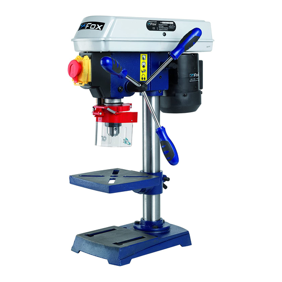
Page 10: Descrizione E Funzione Dei Comandi
DESCRIZIONE E FUNZIONE DEI COMANDI Coperchio pulegge Manopola fissaggio tensionamento cinghia Viti di fissaggio della testa Supporto del piano Supporto della colonna Leva di fissaggio del supporto del piano Base Protezione molla Indicatore di profondità 10. Scala di profondità 11. Colonna 12. -
Page 11: Avvio Del Trapano A Colonna
AVVIO DEL TRAPANO A COLONNA L’interruttore è situato sulla parte frontale della testa del trapano a colonna. Per avviare il trapano, premete il pulsante verde dell’interruttore marcato « I » (AVVIO); per arrestarlo, premete sul pulsante rosso dell’interruttore marcato «O» (ARRESTO). L’interruttore utilizzato su questo utensile è... -
Page 12: Anomalie Di Funzionamento
Salita-discesa dell’albero difficoltosa Pulire e ingrassare l’albero porta mandrino sotto la puleggia ASSISTENZA Tutti gli utensili e accessori Fox sono costruiti e controllati utilizzando le più moderne e sicure tecniche produttive. Se nonostante queste attenzioni un utensile dovesse guastarsi, la riparazione deve essere fatta da... - Page 13 INDEX SAFETY INSTRUCTIONS ........................12 PERSONNEL AUTHORIZED TO USE THE MACHINE ..............12 GENERAL SAFETY INSTRUCTIONS ....................13 SPECIFIC SAFETY INSTRUCTIONS FOR DRILL PRESSES ............14 ENVIRONMENTAL PROTECTION ..................... 14 INFORMATION FOR USERS ......................14 SYMBOLS ............................15 ELECTRICAL CONNECTIONS ......................15 ELECTRICAL CONNECTIONS ......................
-
Page 14: Safety Instructions
SAFETY INSTRUCTIONS WARNING: TO REDUCE THE RISK OF FIRE, ELECTRIC SHOCK AND INJURY WHEN USING ELECTRICAL TOOLS, OPERATORS SHOULD ALWAYS OBSERVE BASIC SAFETY PRECAUTIONS AS WELL AS THE THOSE INDICATED IN THIS MANUAL. Read carefully all the instructions before use this product and keep them safe for future reference. Operations carried out using a power tool can become dangerous for the operator if safe and adequate operating standards are not observed. -
Page 15: General Safety Instructions
16. Do not force the machine. You can obtain better and safer results if you use the machine at the cutting pressure for which it has been designed. 17. Use the suitable tool. Do not use a small tool for an intensive job. Fox example, do not use a circular saw to cut branches or stumps. -
Page 16: Environmental Protection
SPECIFIC SAFETY INSTRUCTIONS FOR DRILL PRESSES 1. DO NOT use the drill press until it is completely assembled and installed according to the instructions of this manual. 2. FIX the drill press on a supporting or flat surface. If the supporting or the flat surface move during use, FIX them to the ground. -
Page 17: Electrical Connections
SYMBOLS Read the instruction manual carefully Use personal protection devices (goggles, dust mask earphones) Serial number / year of production ELECTRICAL CONNECTIONS ELECTRICAL CONNECTIONS Use 230 V 50 Hz alternate voltage equipped with a earthing conductor to supply your machine. Ensure that the power supply corresponds to this voltage, that it is protected by a differential and magnetothermal switch, and that the earthing system is efficient. - Page 18 EXTENSION LEADS Only use three conductors extension leads, with a plug with two plugs and a earthing contact and sockets with two holes and a earth corresponding to the plug of the tool. When using an electric tool at a remarkable distance from the power supply, use an extension lead with sufficient dimensions to transport the current which the tool needs.
- Page 19 REMOVAL OF PACKAGE Your drill press is delivered complete inside the package. Remove the package carefully and check that nothing is missing or damaged. In case there are any faulty or damaged parts, do not use them in order not to compromise tool efficiency and safety. Address to an after sales centre to replace faulty parts.
- Page 20 LOCATION AND FUNCTION OF CONTROLS Pulley guard Belt tension lock handle Head lock set screws Support - table Column - support Support – lock Base Spring cap Depth scale indicator 10. Depth scale 11. Column 12. Bevel scale 13. Table lock set screws Table 15.
- Page 21 STARTING THE DRILL PRESS The switch is located on the front side of drill press’ head. To start the machine, push the green button “I” of the switch (ON); to stop it, push the red button “O” of the switch (OFF). The switch of this tool is an undervoltage switch that prevents the drill press from starting automatically in case of restart of the electric current after an interruption;...
- Page 22 FOX Power Tools and accessories which examination proves to be defective in workmanship or material. The warranty period for FOX brand is one year. Any alleged defective part or parts must be returned prepaid to SERRACON or one of the service centres. The guarantee does not include repair labour or parts replacement required because of misuse, abuse, or normal wear and tear.
- Page 23 TABLE DES MATIERES REGLES DE SECURITE ........................22 PERSONNEL AUTORISÉ À L’UTILISATION DE LA MACHINE ............22 REGLES DE SECURITE GENERALES ..................... 23 REGLES DE SECURITE SUPPLEMENTAIRES POUR LES PERCEUSES A COLONNE ....24 PROTECTION DE L’ENVIRONNEMENT.................... 24 INFORMATION AUX UTILISATEURS .................... 24 SIMBOLI ..............................
-
Page 24: Regles De Securite
REGLES DE SECURITE ATTENTION : TOUT EN SUIVANT LES INSTRUCTIONS MENTIONNÉES DANS CE MANUEL, LORSQUE VOUS UTILISEZ UN OUTIL ÉLECTRIQUE, VOUS DEVEZ TOUJOURS RESPECTER TOUTES LES PRÉCAUTIONS POUR PRÉVENIR LES RISQUES D'INCENDIE, D'ÉLECTROCUTION ET DE BLESSURES. Lisez attentivement ce manuel d’instructions avant de mettre la machine en service et conservez-le soigneusement. -
Page 25: Regles De Securite Generales
REGLES DE SECURITE GENERALES 1. Garder l’aire de travail propre. Les zones de travail et établis encombrés favorisent les blessures. 2. Eviter un environnement dangereux. Ne pas exposer les outils à la pluie et ne pas les utiliser dans des endroits humides ou mouillés. -
Page 26: Regles De Securite Supplementaires Pour Les Perceuses A Colonne
REGLES DE SECURITE SUPPLEMENTAIRES POUR LES PERCEUSES A COLONNE 1. NE PAS utiliser la perceuse à colonne avant de l’avoir complètement montée et assemblée selon les instructions de ce manuel. FIXER la perceuse à colonne sur un support ou une surface plane. Si le support ou la surface bouge pendant l’utilisation, FIXER ces derniers au sol. -
Page 27: Simboli
SYMBOLES Lire attentivement le manuel d'instructions Utiliser des dispositifs de protection personnelle (lunettes, masque anti-poussières et casque antibuit) Numéro de série / année de fabrication. BRANCHEMENT DE LA MACHINE AU COURANT RACCORDEMENT ELECTRIQUE Votre machine comporte un moteur électrique fabriqué avec précision. Elle doit être branchée sur une alimentation de 230 V, 50 Hz. -
Page 28: Cordons Prolongateurs
CORDONS PROLONGATEURS N’utilisez que des cordons prolongateurs à trois conducteurs possédant une fiche à deux broches et des prises à deux cavités et une terre correspondant à la fiche de l’outil. Lorsque vous utilisez un outil électrique à une distance importante de l’alimentation, assurez-vous d’utiliser un cordon prolongateur qui a une dimension suffisante pour transporter le courant dont l’outil a besoin. -
Page 29: Montage De La Perceuse A Colonne
Votre nouvelle perceuse à colonne est livrée complète dans un carton. Déballez-la soigneusement de celui-ci ainsi que toutes les pièces détachées et assurez-vous que rien ne manque et qu'il n'y ait pas de pièces endommagées. Ne jetez pas le carton d’emballage de la machine temps que la perceuse n’a pas été... -
Page 30: Identification De La Machine
IDENTIFICATION DE LA MACHINE Capot d’acces aux poulies Poignee de verrouillage de la tension de la courroie Blocage de la tete Support du plateau Support de la colonne Manivelle du plateau Base Ressort d’alimentation Indicateur de profondeur 10. Echelle de profondeur 11. -
Page 31: Demarrage De La Perceuse A Colonne
DEMARRAGE DE LA PERCEUSE A COLONNE L’interrupteur est situé sur la face avant de la tête de la perceuse. Pour démarrer la machine, appuyez sur le bouton vert « I » de l’interrupteur (ON); pour l’arrêter, appuyez sur le bouton rouge « O » de l’interrupteur (OFF). -
Page 32: Anomalies De Fonctionnement
ANOMALIES DE FONCTIONNEMENT INCONVÉNIENT CAUSES POSSIBLES Manque de courant dans la prise à laquelle est connecté le câble d'alimentation La perceuse ne fonctionne pas Câble d'alimentation défectueux Moteur en panne Couvercle du boîtier poulie ouvert Outil non aiguisé de façon appropriée Outil non approprié... - Page 33 KIRKCALDY UK KY1 3PD KIRKCALDY UK KY1 3PD dichiara che la macchina: déclare que la machine: TRAPANO A COLONNA F12-921A PERCEUSE A COLONNE F12-921A prodotta nel (vedi etichetta riportata): produite en (voir étiquette reportée): è conforme alle disposizioni della Direttiva 2006/42/CE e est conforme aux dispositions de la 2006/42/CE et aux alle disposizioni di attuazione;...
- Page 34 F12-921A ESPLOSO / EXPLODED VIEW / VUE ECLATEE / RÄJÄYTYSKUVA...
- Page 35 F12-921A Art. Art. Art. / Item Art. / Item F12921-79 F12921-01 F12921-40 F12921-80 F12921-02 F12921-41 F12921-81 F12921-03 F12921-42 F12921-82 F12921-04 F12921-43 F12921-83 F12921-05 F12921-44 F12921-06 F12921-45 F12921-07 F12921-46 F12921-08 F12921-47 F12921-09 F12921-48 F12921-10 F12921-49 F12921-11 F12921-50 F12921-12 F12921-51 F12921-13 F12921-52...
- Page 36 SCHEMA ELETTRICO / WIRING DIAGRAM / SCHEMA ELECTRIQUE / SÄHKÖKYTKENTÄKAAVIO PE – Circuito di protezione - Protection circuit - Circuit de protection - Suojapiiri FCT – Microinterruttore - Microswitch – Microcontacteur - Mikrokytkin IG – Interruttore generale - Main switch - Interrupteur général - Valopääkatkaisin C –...
Need help?
Do you have a question about the F12-921A and is the answer not in the manual?
Questions and answers