
Related Manuals for Fujitsu UTP-VX60A


Summary of Contents for Fujitsu UTP-VX60A
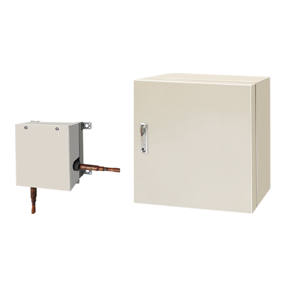
- Page 1 INSTALLATION MANUAL DX-kit For authorized service personnel only. UTY-VDGX UTP-VX30A UTP-VX60A UTP-VX90A [Original instructions] PART NO. 9381279005...
-
Page 2: Table Of Contents
INSTALLATION MANUAL This mark indicates procedures which, if improperly performed, CAUTION might possibly result in personal harm to the user, or damage to PART NO. 9381279005 property. VRF system DX-kit Read carefully all security information before use or install the DX-kit. Do not attempt to install the DX-kit or a part of the DX-kit by yourself. -
Page 3: Accessories
Name and Shape Q’ty Application 2.3. Accessories Thermistor spring (For small thermistor For mounting the thermistor holder pipe) WARNING For installation purposes, be sure to use the parts supplied by the manufacturer or Thermistor spring (For large thermistor For mounting the thermistor other prescribed parts. -
Page 4: Optional Parts
3.2. System Design 3.1. Product Lineup 3.2.1. Basic Refrigerating System Confi guration (1) Product Lineup Using the DX-kit enables indoor units manufactured by other than Fujitsu general to be Unit Name Model Name Environment specifi cations used in the Fujitsu general refrigerant system. -
Page 5: Installation Work
Fujitsu general remote controllers and control devices directly control Fujitsu general out- that they cannot reach the unit. door units and indoor units (refrigerant cycle devices, etc.) not manufactured by Fujitsu general. A system confi guration example is shown below. -
Page 6: Installing The Control Unit
4.3.1. Installing the Control unit 4.3.2.3. Mounting Secure Fittings (If Using 1 EEV unit) (1) Use the 8 screws (accessories) to secure the secure fi ttings (accessories). • If installing outdoors, make sure to orient A upwards. • Using a template (accessory) is recommended when positioning the holes for mounting Tightening torque the control unit. -
Page 7: Pipe Installation
Prohibited EEV unit orientations 5.3. Bending pipes PROHIBITED • The pipes are shaped by your hands or pipe bender. Be careful not to collapse them. • Do not bend the pipes in an angle more than 90°. • When pipes are repeatedly bend or stretched, the material will harden, making it diffi cult to bend or stretch them any more. -
Page 8: Installing Heat Insulation
C: Inlet air thermistor/D: Outlet air thermistor 5.5. Installing heat insulation Install in a location where the effects of heat sources such as heat exchangers and heat- ers, etc., are minimized as far as possible. CAUTION Inlet air thermistor Outlet air thermistor (Accessories) (Accessories) After checking for gas leaks (refer to the Installation Manual of the outdoor unit),... -
Page 9: Electrical Requirement
*1: When connecting to the Heat Recovery System, refer to the installation manual of the RB unit. • The following breaker specifi cations apply only to connections for Fujitsu general indoor *2: When connecting the 2-wire type remote controller, Y3 is not used. - Page 10 A. For solid core wiring 7.3.2. Transmission cable, Remote controller cable and (1) To connect the electrical terminal, follow the below diagram and connect after looping External interface cable it around the end of the cable. Transmission cable (2) Use the specifi ed cables, connect them securely, and fasten them so that there is no stress placed on the terminals.
-
Page 11: Connection Of Wiring
Cable holes with mounted cable glands (accessories) 7.4. Connection of wiring Cable gland Diameter Insertable cable Hole No. type (mm) dimensions (mm) 7.4.1. Terminal Explanation and Cable Holes Large Φ20.0 Φ6 to 12 • Only one cable can be passed through each cable hole. To pass multiple cables H5, H6, H7, H9, H10 Medium Φ16.2... - Page 12 7.4.2. Connecting the Cables • Outdoor cable connections (1) Thermistor cable connections CAUTION • Connect the thermistor cables to the relay multi-conductor cables as shown in the diagram before passing through the hole. Pay attention to the following during installation. Failure to do so may cause water •...
-
Page 13: External Input And External Output (Optional Parts)
(3) Wiring the remote controller cable (device side) 7.5. External input and external output (Optional parts) 7.5.1. Digital external inputs • Select either the apply voltage method or dry contact method for digital external inputs. • Both types of terminals cannot be used simultaneously. For 2-wire type For 3-wire type •... - Page 14 When connected to Apply voltage terminals of multiple DX-kits with a connected unit, be sure to (1) ON/OFF SIGNAL (INPUT) make a branch outside the DX-kit using a pull box, etc. as shown on below example. [For the “Edge” input method, function settings “60”=00] Terminal block Input signal Command...
- Page 15 7.5.2. Analog external inputs • Precautions for Type-i If connecting a dielectric load such as a relay Changing the voltage of the signals entered to “analog external inputs” enables you to set coil, etc., to the connected device, make sure to either the operation temperature or the required operation performance.
-
Page 16: Field Setting
8.1. Setting the address • Set this address if connecting a Fujitsu general remote controller. • If using analog inputs, Fujitsu general remote controller operation will be disabled. 8.1.1. Setting the indoor unit address and refrigerant circuit If using analog inputs , DX-kit cannot form the remote controller group. -
Page 17: Dip Switch Setting
8.2. Dip switch setting 8.3. Function setting (1) Capacity settings of indoor units to be controlled • FUNCTION SETTING can be performed with the wired or wireless remote controller. The capacity of indoor units to be controlled is set. (The remote controller is optional equipment) Indoor unit Dip switch setting (*: factory setting) •... -
Page 18: Test Run
Indoor unit main PCB error • Refer to the Installation Manual for the remote controller to perform the test run using Indoor unit the remote controller. (If using analog inputs, Fujitsu general remote controller operation communication circuit will be disabled.) (10) -
Page 19: Operations
a) Using the inlet to control the temperature 12. OPERATIONS Cooling Heating 30°C 30°C 12.1. Analog external inputs 18°C 10°C CAUTION • Use an insulated screwdriver to set the adjustment dial. 4.2 V 9.0 V 1.0 V 9.0 V • Do not apply voltage greater than 10V. Input voltage Input voltage The operation temperature and required operation performance are set by changing the...
Need help?
Do you have a question about the UTP-VX60A and is the answer not in the manual?
Questions and answers