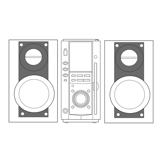
Aiwa xr-ms3 Service Manual
Hide thumbs
Also See for xr-ms3:
- Operating instructions manual (68 pages) ,
- Service manual (26 pages) ,
- Service manual (16 pages)
Table of Contents
Advertisement
Quick Links
SERVICE MANUAL
COMPACT DISC
STEREO SYSTEM
• This Service Manual contains the additional information "CD ELECTRICAL SECTION"
for the model XR-MS3 (U,HC). If requiring the other information, see Service Manual of
XR-MS3 (U,EZ), (S/M Code No. 09-002-422-6R1),
XR-MS3 (HC), (S/M Code No. 09-008-422-6R2).
XR-MS3
BASIC TAPE MECHANISM : 2ZM-1 R10NM/
BASIC CD MECHANISM : TN-CCD1001-902M
S/M Code No. 09-00A-422-6S4
U, HC
2ZM-1 YR10NC
Advertisement
Table of Contents

Summary of Contents for Aiwa xr-ms3
- Page 1 BASIC CD MECHANISM : TN-CCD1001-902M • This Service Manual contains the additional information “CD ELECTRICAL SECTION” for the model XR-MS3 (U,HC). If requiring the other information, see Service Manual of XR-MS3 (U,EZ), (S/M Code No. 09-002-422-6R1), XR-MS3 (HC), (S/M Code No. 09-008-422-6R2).
-
Page 2: Protection Of Eyes From Laser Beam During Servicing
PROTECTION OF EYES FROM LASER BEAM DURING SERVICING This set employs laser. Therefore, be sure to follow carefully CAUTION the instructions below when servicing. Use of controls or adjustments or performance of proce- dures other than those specified herin may result in WARNING!! hazardous radiation exposure. -
Page 3: Electrical Main Parts List
ELECTRICAL MAIN PARTS LIST REF. NO. PART NO. KANRI DESCRIPTION REF. NO. PART NO. KANRI DESCRIPTION 87-010-831-080 C-CAP,0.1U-16V 87-010-831-080 C-CAP,0.1U-16V 8A-CG5-602-010 IC,CXP84332-169Q 87-010-831-080 C-CAP,0.1U-16V 87-A21-533-030 IC,CXD2587Q 87-010-831-080 C-CAP,0.1U-16V 87-A21-596-040 IC,CXA2570N 87-012-358-080 C-CAP,0.47U-16V 87-A20-711-040 IC,BA5970FP 87-A21-777-040 IC,BA6289F 87-010-831-080 C-CAP,0.1U-16V 87-010-831-080 C-CAP,0.1U-16V 87-A21-847-040 IC,UPC842G2 87-012-188-080... -
Page 4: Wiring - 1 (Main)
WIRING – 1 (MAIN) MAIN C.B MAIN C.B (COMPONENT SIDE) (CONDUCTOR SIDE) (SLED MOTOR) (SPINDLE MOTOR) (LOADING MOTOR) (PICK UP DET SW) NOTE Cxxx Rxxx Lxxx ZDxxx – 4 –... - Page 5 WIRING – 2 (SW) SW C.B TO MAIN C.B (DISC DET) (DISC DET) (DISC DET) (DISC DET) – 5 –...
-
Page 6: Schematic Diagram
SCHEMATIC DIAGRAM MAIN C.B Communication Lines SW C.B LOADING MOTOR DRIVER (DISC DET) (DISC DET) RESET LOADING MOTOR SYSTEM CONTROL MOTOR DRIVER (DISC DET) SLED MOTOR (DISC DET) SPINDLE MOTOR PICK UP DET SW ESE11HS2 LD SW DIGITAL SERVO, DAC,DSP DIGITAL FILTER LD SW Digital... -
Page 7: Ic Block Diagram
IC BLOCK DIAGRAM – 7 –... - Page 8 IC DESCRIPTION IC, CXD2587Q Pin No. Pin Name Description SQSO Sub-Q 80-bit, PCM peak and level data output. CD TEXT data output. SQCK SQSO Clock input for reading. XRST System reset. Reset at "L". SYSM Muting input. Muted at "H". DATA Serial data input from CPU.
- Page 9 Pin No. Pin Name Description Sled error signal input. Tracking error signal input. Center servo analog input. RFDC RF signal input. ADIO For test. (Not used) AVSS0 – Ground of analog circuits. IGEN Constant current input for OP amp. AVDD0 –...
- Page 10 NOTES • PCMD is a MSB first, two's complement output. • GTOP is used to monitor the frame sync protection status. (High: sync protection window released.) • XUGF is the frame sync obtained from the EFM signal, and is negative pulse. It is the signal before sync protection.
-
Page 11: Cd Mechanism Exploded View
CD MECHANISM EXPLODED VIEW 1 / 1 DET SW ESE22MH1 30 31 32 DET SW ESE22MH3 DET SW ESE11HS2 FD GR(C) – 11 –... - Page 12 CD MECHANISM PARTS LIST 1 / 1 REF. NO. PART NO. KANRI DESCRIPTION REF. NO. PART NO. KANRI DESCRIPTION 1 S3-031-110-030 EARTH SPR 41 S3-031-010-500 FIX PL(L)Z 2 S3-031-110-180 L.P SPRING(L) 42 S3-031-050-310 FD SCREW(M) 3 S3-031-110-010 FRONT BRKT 43 S3-031-010-530 HUNG DOWN SPRING(A) 4 S3-031-113-010 LDG MOTOR ASSY...
- Page 13 2–11, IKENOHATA 1–CHOME, TAITO-KU, TOKYO 110, JAPAN TEL:03 (3827) 3111 9301978 0251431 Printed in Singapore...


Need help?
Do you have a question about the xr-ms3 and is the answer not in the manual?
Questions and answers