Table of Contents
Advertisement
Advertisement
Table of Contents

Related Manuals for Abloy DA400

Summary of Contents for Abloy DA400
- Page 1 ABLOY DA400 ® – Swing door operator PICOMED PROGRAM VERSION 1.5...
-
Page 2: Table Of Contents
CONTROL POINTS Control points CONNECTIONS Internal connections External connections BATTERY OPERATION Battery operation Battery adapter FIRE DOOR SYSTEM Fire door system according UL requirements ABLOY fire door system PROGRAMMING HANDSET Programming handset CONNECTION EXAMPLES Connection examples Connections with electric locks... - Page 3 ABLOY's extensive network of sales and after-sales service points will ensure long and trouble-free service life for the automatic swing door operator. The automatic swing door operator has been approved by the Electrical Inspectorates of FINLAND, DENMARK, NORWAY and SWEDEN.
- Page 4 GENERAL INFORMATION Approvals Low Voltage Directive (Finland, Sweden, Norway, Denmark) EMC Directive (European Community) UL (United States of America) CSA and ULC (Canada) Fire door use (Finland, USA, Canada) Warnings Closing force must not exeed 178 N (40 lb) for a pedestrian application. Closing time for last 10°...
-
Page 5: Technical Data
TECHNICAL DATA The automatic swing door operator is intended for both new and existing swing door applications, internal and opening out external doors. The automatic swing door operator can be used in residential units, institutions, shops, public buildings, warehouses and offices. echnical data Operating conditions Supply voltage 115/230 V AC... -
Page 6: Construction & Operation
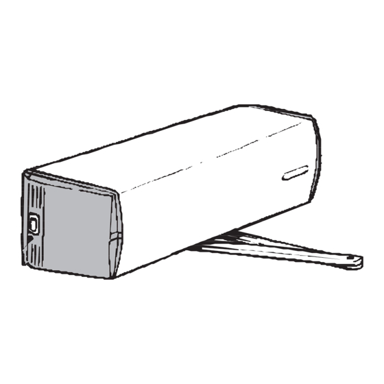
CONSTRUCTION & OPERATION The operation of the ABLOY automatic swing door operator is controlled by a microprocessor. The body and the housing of the operator are manufactured from aluminium. The body is secured to the wall or transom by four fixed bolts following the installation of the mounting plate with the power switch side of the unit mounted towards the hinge side of the door. -
Page 7: Removal Of Housing
REMOVAL OF HOUSING Disconnect mains supply when removing or mounting the housing. Remove the housing by inserting a wide-blade screw driver at each end. SWITCHES The automatic swing door operator is mounted mains switch with the end to the located towards the hinge side of the door. When the door operator is switched on, the red LED on the mains switch lights up. -
Page 8: Installation
INSTALLATION Inspect the swing door operator against transport damage. Test the free swinging of the door, which should open and close smoothly. The automatic swing door operator is to be installed on the transom, with the mains switch located towards the hinge. push function , the door operator is mounted on the stop side of the door installing the standard arm 7281 or 7282. - Page 9 INSTALLATION Drill the installation holes as shown in the drilling diagrams. Attach the door operator to the mounting plate with four screws M8 x 25 provided. Use the mounting plate delivered with the door operator ensuring the installation base is level and securely fixed. Minimum wall thickness should be 5 mm if the door frame is of metal construction.
- Page 10 INSTALLATION Drill the installation holes as shown in the drilling diagrams. Attach the door operator to the mounting plate with four screws M8 x 25 provided. Use the mounting plate delivered with the door operator ensuring the installation base is level and securely fixed. Minimum wall thickness should be 5 mm if the door frame is of metal construction.
-
Page 11: Electrical Connections
Wiring diagram: Any impulse device with ABLOY a potential-free output may be connected to the door operator. 4x 0,22mm ABLOY locks and impulse devices should Safety sensor be made by using 3x 0,22mm flexible multicore cable Remote control of a type suitable for signal equipment. - Page 12 ADJUSTMENT OF DOOR MOVEMENTS Pulse disk A pulse disk fitted to the drive shaft is used to determine the door closed position. This is achieved by the pulse counter calculating a series of holes aroung the circumference of the disk, one of which is open. When the perimeter sensor locates the edge of the notch the door operator stops the door.
- Page 13 ADJUSTMENT OF THE DOOR MOVEMENTS Control unit adjustments and selections Control unit: When the mains supply is connected, the control unit immediately adopts the status determined by the program selector and the opening pulses. Only the green OK LED is lit. Press one of the three buttons and the display will show the status of the door operator.
-
Page 14: Control Points
ADJUSTMENT OF DOOR MOVEMENTS Buttons: a) Selection+ button This button is used to call control points 0...28 onto the display. With the light on the digital display, press the Selection+ button for at least 3 seconds enabling yellow Adjustment LED to light. Digit 1 with a signal dot... -
Page 15: Control Points
CONTROL POINTS max. 100 Control points and control values Control points are presented in numerical order 0...28. Study all the control points to ensure the optimum possible operation of the door. Adjust the functions ensuring the safety clutch does not slip. Control point Control Description... - Page 16 CONTROL POINTS Control point Control Description Factory value setting 1...8 Safety feature sensitivity (Sealed) 1 or 0 Power-assisted manual opening 0...2 Selection of arm (and restoring factory settings) (Sealed) 0...2 Battery operation 0...60 Power-assisted manual opening: hold open time 0...60 Inside impulse: Hold open time 1 or 0 Operation of lock control relay...
- Page 17 CONTROL POINTS The opening angle, where the operator changes from initial speed to final speed. (1 digit = approx. 2°) Ensure adequate angle for final speed! Hold open angle. (1 digit = approx. 2°) The closing angle where the operator changes from initial speed to final speed.
- Page 18 CONTROL POINTS The operator keeps the door closed at preset force for 1 second following which this reduced to half of the preset value. Value 0 = no lock-up force. The safety feature stops the door movement for 3 seconds if an obstacle is detected in the door movement range.
- Page 19 CONTROL POINTS The operator drives the door against the closed position for a preset value of 1 second. Fire doors - adjust the lock control relay hold time to a minimum. Sequencing 1 = Opening and closing sequencing for pair of rebated doors The master door opens first and then the slave.
- Page 20 CONTROL POINTS The counter indicates number of openings. The fixed obsticles in safety sensor zone can be excluded by adjusting the area smaller than the door open position. Dispalys the program version. VERSION 0= DA400 Europe 1= DA400 UL (North America)
- Page 21 CONTROL POINTS Programming examples A safe door: The safety of the door operator is controlled by basic adjustments; operator force, speeds, safety feature sensitivity, operator's force and hold open time. - The operator force is an important adjustment. A high control value affects to the safety feature and also to its sensitivity.
-
Page 22: Connections
INTERNAL CONNECTIONS Sequencing Pulse counter Resistor 1000 ohm Motor black Locking Battery black circuit black black blue CONTROL UNIT Ground Mains switch T 800mA Ground 115V 230V Select the right supply voltage with the brown wire OPEN AUTO Remove connections, when using Permanent wiring shall be separate... - Page 23 Power-supply cord through Power-supply cord through the end of housing the base plate Max 200 mm ABLOY Max 200 mm The power supply cord shall not be - routed through doorways, window openings, walls, ceilings, floors or the like. - attached or otherwise secured to the building structure.
-
Page 24: External Connections
Only voltage free switches with a normally open output can be used to control the ABLOY automatic swing door operator. Moreover, the total resistance of the control switch and its wiring must not exceed 100 ohm, when the switch is closed. -
Page 25: Battery Operation
Prevents the door opening if the circuit is open and door fully closed. For example use a locking circuit micro switched keep such as the ABLOY 8400. Note! Use always use a locking circuit when there is a lock fitted to the door. -
Page 26: Battery Operation
BATTERY OPERATION Battery operation is possible by addition of a battery or batteries and battery adapter to the operator. During a power failure the operator will revert to the chosen battery operation mode. See Control point 15. Fire door use ;... - Page 27 BATTERY OPERATION Fire door use; when there is a smoke alarm fitted the operator reverts to MANUAL mode, following which the door closes after a preset delay. During a smoke alarm the door is opened manually and closes automatically after a preset delay. Adjust the delay to minimum (control point 16).
- Page 28 BATTERY OPERATION 12 V Full battery backup; The operator and devices connected will operate during a power failure. The operation time depends on number of openings and the current draw of the devices fitted. When battery backup is chosen, the battery is checked by the operator and the following should be noted: BATTERY VOLTAGE 2.0 V...
- Page 29 BATTERY OPERATION 24 V Full battery backup; The operator and devices connected will operate during a power failure. The operation time depends on number of openings and the current draw of the devices fitted. When battery backup use is chosen, the battery is checked by the operator and the following should be noted: BATTERY VOLTAGE 15 V...
-
Page 30: Battery Adapter
BATTERY ADAPTER In the adapter there is two relay outputs and one input. The outputs are power alarm and battery alarm. The input is for connecting smoke detectors. The power alarm indicates if there is a power failure and the battery alarm indicates if the battery voltage drops under 11.5V. -
Page 31: Fire Door System According Ul Requirements
FIRE DOOR SYSTEM ACCORDING UL REQUIREMENTS Battery adapter is used in the fire doors when there is a need to meet e.g the UL requirements. In the adapter there is two relay outputs and one input. The outputs are power alarm and battery alarm. The input is for connecting smoke detectors. -
Page 32: Abloy Fire Door System
ABLOY FIRE DOOR SYSTEM (Not according UL regulations) The ABLOY DA400 for fire doors with ABLOY smoke detectors and relays Diagram gray yellow Max two smoke detectors DA400 Relay 453 Relay 453 N.C. N.C. White Yellow Blue Black white PLEASE NOTE,... -
Page 33: Programming Handset
PROGRAMMING HANDSET 4-Digit Transmitter Display Change Decrease A B LO Y Control point Power switch Increase Set value Reset error 9V Battery (Lithium or Alkaline) Control values 1. Switch power ON 2. Enter master code and press 2. Find control point and adjust value 3. -
Page 34: Connection Examples
CONNECTION EXAMPLES OUTWARD Door operator 1: Note! inward traffic Disconnect mains supply - outer door opens and remove the battery cable before making first any connections! - inner door's delay adjusted on door Radar operator 2 Tandem doors; stepwise opening The example is for tandem NOTE! Use NOTE! Use pair twisted, shielded cable... -
Page 35: Connections With Electric Locks
21 to enable to drive the door closed for 0.4 seconds allowing the green latch freedom of movement blue - ABLOY lead cover 8810 or black 8811 should always be used for swing door situations. Motor locks 8329, 8904, 8910 - the impulse device opens both the lock and the door. - Page 36 Motor locks 8120, 8320 Before connections switch the power off - the impulse device opens and remove battery. both the lock and the door. - ABLOY lead cover 8810 or 8811 should always be used for swing door situations. DA400 8120, 8320 15/17...
- Page 37 24 VDC - the door operator receives the locking circuit information from the 12 VDC microswitch in the lock case. 15/17 - ABLOY lead cover 8810 or 8811 should always be used for swing door situations. green blue black Note! Make sure you choose the correct...
- Page 38 +(358) 13-2502 209 http://www.abloy.com Abloy Oy is an ASSA ABLOY Group company. The ASSA ABLOY Group is the wordl’s leading manufacturer and supplier of locks and associated products, dedicated to satisfying end-user need for security, safety and convenience.