
Related Manuals for Abloy DA400

Summary of Contents for Abloy DA400
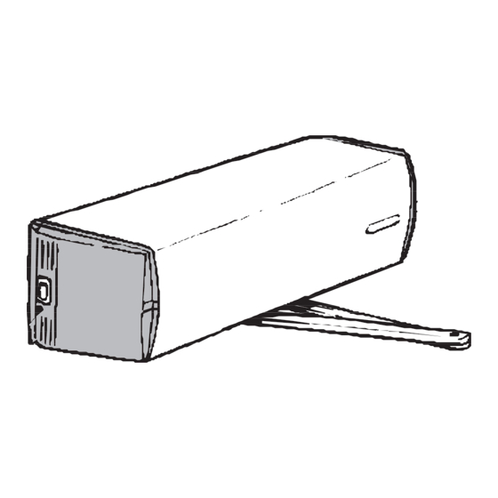
- Page 1 [--_._. ~ABLOY~ ABlOyID DA400 - Swing door operator". ~-----------_._---- .' OJ' f'(" (y'l ~~_V ER_SIO_N_1,_5 All ASSA A810Y Group co~y...
-
Page 2: External Connections
Only voltage free switches with a normally open output can be used to control the ABLOY automatic swing door operator. Moreover, the total resistance of the control switch and its wiring must not exceed 100 ohm, when the switch is closed. - Page 3 Prevents the door opening if the circuit is open and door fully closed, For example use a locking circuit micro switched keep such as the ABLOY 8400. Note! Use always use a locking circuit when there is a lock fitted the door, Outside impulse...
-
Page 4: Internal Connections
INTERNAL CONNECTIONS Sequencing Pulse counter Resistor 1000 ohm <2) Motor loci< Locking '"" " arcuit Battery <2) " leek .'lId< " " CONTROL UNIT Mains JCJ[- switch _I:J T 800rllA 1I5V 230V Select the right supply voltage with the brown wire O PEN MANUAL AUTO... - Page 5 ADJUSTMENT OF DOOR MOVEMENTS Pulse disk A pulse disk fitted to the drive shaft is used to determine the door closed position. This is achieved by the pulse counter calculating a series of holes aroung the circumference of the disk, one of which is open. When the perimeter sensor locates the edge of the notch the door operator stops the door.
- Page 6 ADJUSTMENT OF THE DOOR MOVEMENTS Control unit adjustments and selections Control unit: When the mains supply is connected, the control unit immediately adopts the status determined by the program selector and the opening pulses. Only the green OK LEDis lit. Press one of the.
- Page 7 -;i;.=-::--=~ ._--- ADJUSTMENT DOOR MOVEMENTS Buttons: a) Selection+ button This button is used to call control points 0...28 onto the display. With the light on the digital display, press the Selection+ button for at least 3 seconds enabling yellow Adjustment LEDto light. Digit 1 with a signal dot appears on the right-hand side (;]11 digital display to indicating the first control point.
-
Page 8: Control Points
CONTROL POINTS 100. max. Control points and control values Control points are presented in numerical order 0 ... 28. Study all the control points to ensure the optimum possible operation of the door. Adjust the functions ensuring the safety clutch does not slip. Control point Control Description... - Page 9 CONTROL POINTS Description Control point Control Factory va ue 1...8 Safety feature sensitivity (Sealed) 1 or 0 Power-assisted manual opening f-._- .0" 0...2 Selection of arm (and restoring factory settings) (Sealed) ----- [][5] 0...2 Battery operation --Db] 0...60 Power-assisted manual opening: hold open time ._--_.
- Page 10 CONTROL POINTS The opening angle, where the operator changes from initial speed " " to final speed. (1 digit ~ approx. 2°) Ensure adequate angle for final speed! Hold open angle. (1 digit ~ approx. 2°) The closing angle where the operator changes from initial speed "...
- Page 11 CONTROL POINTS The operator keeps the door closed at preset force for 1 second following which this reduced to half of the preset value. Value 0 no lock-up force. The safety. feature stops the door movement for 3 seconds If an obstacle is detected In the door movement range.
- Page 12 CONTROL POINTS The operator drives the door against the closed position for a preset value of 1 second. Fire doors - adjust the lock control relay hold time to a minimum. Sequencing Opening and closing sequencing for pair of rebated doors The master door opens first and then the slave.
- Page 13 CONTROL POINTS The counter indicates number of openings. The fixed obsticles in safety sensor zone can be excluded by adjusting the area smaller than the door open position. Dlspalys the program version. VERSION 0= DA400 Europe 1= DA400 UL (North America)
-
Page 14: Battery Operation
BATTERY OPERATION Battery operation is possible by addition of a battery or batteries and battery adapter to the operator. During a power failure the operator will revert to the chosen battery operation mode. See Control point 15. Fire door use; when there is a smoke alarm fitted the operator reverts to MANUAL mode, following which the door closes after a preset delay. -
Page 15: Battery Voltage
,CO' BATTERY OPERATION Fire door use; when there is a smoke alarm fitted the operator reverts to MANUAL mode, following which the door closes after a preset delay. During a smoke alarm the door is opened manually and closes automatically after a preset delay. Adjust the delay to minimum (control point 16). - Page 16 BATTERY OPERATION 12 V Full battery backup; The operator and devices connected will operate during a power failure. The operation time depends on number of openings and the current draw of the devices fitted. When battery backup ;s chosen, the battery is checked by the operator and the following should be noted: BATTERYVOLTAGE 2.0V...
- Page 17 BATTERY OPERATION 24 V Full battery backup; The operator and devices connected will operate during a power failure. The operation time depends on number of openings and the current draw of the devices fitted. When battery backup use is chosen, the battery is checked by the operator and the following should be noted: BATTERYVOLTAGE 15 V...
-
Page 18: Battery Adapter
BATTERY ADAPTER In the adapter there is two relay outputs and one input. The outputs are power alarm and battery alarm. The input is for connecting smoke detectors. The power alarm indicates if there is a power failure and the battery alarm indicates if the battery voltage drops under 11.5V.
Need help?
Do you have a question about the DA400 and is the answer not in the manual?
Questions and answers