Table of Contents
Advertisement
LANCER CORP
6655 Lancer Blvd.
San Antonio, Texas 78219
To order parts, call
Customer Service: 800-729-1500
Warranty/Technical Support: 800-729-1550
Email: custserv@lancercorp.com
www.lancercorp.com
February 2013
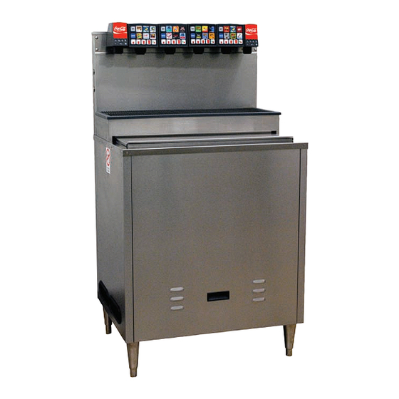
COLD CARB ICE COOLED DISPENSER
SERIES 23308 - FREESTANDING
Installation and Service Manual
PN 28-0752/02
"Lancer" is the registered trademark of Lancer Corp © 2013 by Lancer Corp, all rights reserved.
1
Advertisement
Table of Contents

Related Manuals for lancer 23308 SERIES


Summary of Contents for lancer 23308 SERIES
- Page 1 LANCER CORP 6655 Lancer Blvd. San Antonio, Texas 78219 To order parts, call Customer Service: 800-729-1500 Warranty/Technical Support: 800-729-1550 Email: custserv@lancercorp.com www.lancercorp.com February 2013 “Lancer” is the registered trademark of Lancer Corp © 2013 by Lancer Corp, all rights reserved.
-
Page 2: Table Of Contents
TABLE OF CONTENTS SPECIFICATIONS..............................3 SAFETY................................3 1. INSTALLATION OF LANCER ICE COOLED DISPENSER................4 RECEIVING............................4 UNPACKING ............................4 WATER SUPPLY ..........................4 CARBONATOR PUMP ........................4 ELECTRICAL SUPPLY ........................4 CONNECTION OF THE EqUIPMENT....................4 START UP ............................5 ADJUSTING WATER FLOW ......................5 ADJUSTING WATER TO SYRUP RATIO (BRIX) ................6 2. -
Page 3: Specifications
SPECIFICATIONS WIDTH: 30 1/8 inches (765 mm) DEPTH: 24 1/2 inches (622 mm) HEIGHT (with legs): 56 1/2 inches (1435 mm) WEIGHT EMPTY: 381 pounds (173 kg) OPERATING: 511 pounds (232 kg) SHIPPING: 470 pounds (213 kg) ICE BIN CAPACITY: 130 pounds (59 kg) SAFETY GROUNDING The power supply must be properly electrically grounded to avoid... -
Page 4: Installation Of Lancer Ice Cooled Dispenser
1. INSTALLATION OF LANCER ICE COOLED DISPENSER 1.1 RECEIVING Each unit is tested under operating conditions and inspected before shipment. At the time of shipment, the carrier accepts responsibility for the unit. Upon receiving the unit, carefully inspect the carton for visible damage. -
Page 5: Start Up
5. Connect the water inlet line to the pump. Complete the water line connection between the pump and the water inlet to the carbonator at the bottom of the dispenser. 6. Provide a suitable drain in the plumbing system and attach the 3/4 inch (1.90 cm) diameter schedule 40 PVC drains to it. -
Page 6: Adjusting Water To Syrup Ratio (Brix)
3. Remove the diffuser by pulling down. 4. Install Lancer yellow syrup separator (PN 54-0031) in place of the nozzle. 5. Activate the dispensing valve to fill the separator syrup tube. 6. Hold a brix cup under the syrup separator and dispense water and syrup into the cup for four seconds. Divide the number of ounces (ml) of water in the cup by four to determine the water flow rate per second. -
Page 7: System Startup
2.2 SYSTEM STARTUP 1. Pour several drinks from each MVU to prime for beverages. 2. Prime all flavor shots. 2.3 PROGRAM THE MULTI VALVE UNIT (MVU) All units are factory pre-set with the following: MVU #1 (Right Side) POSITION WATER/ SODA Water Type Soda Soda... - Page 8 MVU #4 (Left Side) POSITION WATER/ SODA Water Type Plain Soda Soda Water Water Shot Virtual B&F Brand Sold Out On No Yes* *Virtual brands indirectly report a Sold Out from association with a sub-flavor that has Sold Out enabled. For ex- ample, in MVU #4 (above), if position B reports a Sold Out, position E will also report a Sold Out because position B is a sub-flavor of position E.
- Page 9 STEP 2 Press a Brand button to change that beverage from “water off” to “plain water on”. LED will illuminate and stay on for non-carb beverages. Press the same brand button again to switch from non-carb to carb. Press the button one more time to turn the water off for that valve (if position is used for a flavor shot only).
-
Page 10: Set Mvu For Flavor Shots
2.4 SET MVU FOR FLAVOR SHOTS STEP 1 Press both A and C brand buttons (at the same time) on the MVU panel for five seconds to get into programming mode. STEP 2 Press the “Shot” button. The “Shot” button will illuminate. Brands enabled for shots will be illuminated. -
Page 11: Virtual Brand Programming
STEP 5 Press the Pour/Cancel Button to lock the changes in place and exit the programming mode. NOTE: The program will save automatically in 60 seconds if no additional changes are made in that time frame; however, you can exit any time within the 60 second window by pressing Pour/Cancel. -
Page 12: Programming Brands For Sold Out
STEP 4 Select shot. LED will blink quickly. STEP 5 Press the Pour/Cancel button to lock the changes in place and exit the program mode. NOTE: The program will save automatically in 60 seconds if no additional changes are made in that time frame; however, you can exit any time within the 60 second window by pressing Pour/Cancel. - Page 13 STEP 2 Select Sold Out Input 1. The LED will illuminate. STEP 3 Select Sold Out Input 2. The LED will blink slowly. STEP 4 Press the Pour/Cancel button to lock the changes and exit the program mode. NOTE: The program will save automatically in 60 seconds if no additional changes are made in that time frame;...
-
Page 14: Flow Rate Check
2.7 FLOW RATE CHECK The Dispenser’s water flow rate can be checked/calibrated using the on board computer as a timer. To check/adjust flow rate: STEP 1: Remove splashguard and module cover to expose syrup flow controls and solenoids. Remove tower cap to expose the soda and plain water flow controls. -
Page 15: Ratio Process
STEP 3 Remove outer nozzle and insert syrup separator (Lancer PN 82-3964/01). This is important to do during flow rate check so you can determine if the separator has been properly installed. NOTE: Water will leak through to the syrup chamber if not properly installed. -
Page 16: Portion Control Programming (Mvu) (No Topoff)
2.9 PORTION CONTROL PROGRAMMING (MVU) (NO TOP-OFF) STEP 1 Press the S and XL at the same time for five seconds to enter the portion setting mode. The Pour/Cancel light will illuminate and the shot light will blink two times. STEP 2 Press the Brand button. -
Page 17: Portion Control Programming With Top-Off (Mvu)
STEP 4 Repeat this step for each of the other size cups. STEP 5 Select other brands and repeat these steps for each of them. Press the “Pour/Cancel” button to save programming. NOTE: The program will save automatically in 60 seconds if no additional changes are made in that time frame;... - Page 18 STEP 2 Press the brand button. The selected brand’s LED will illuminate. Multiple brands can be programmed at the same time to pour the same amounts for each size during this step. Do this by selecting several brand buttons; however, the first button selected will illuminate and only its beverage will pour.
-
Page 19: Shot Size Programming
2.11 SHOT SIZE PROGRAMMING Flavor shot portions can be adjusted using the MVU touchpad and a graduated cylinder. To adjust flavor shots: STEP 1 While in Portion Control Programming, press the Shot button. Pressing the Shot button again will exit Shot Size Programming. -
Page 20: Dispenser Operation
STEP 4: Repeat steps 2 and 3 for each of the other brands. STEP 5: Press Pour/Cancel to save the settings. NOTE: The Program will save automatically in 60 seconds if no additional changes are made in that time frame; however, you can exit any time within the 60 seconds window by pressing Pour/Cancel. -
Page 21: Final Assembly
3.2 CLEANING AND SANITIZING SYSTEMS General Information Lancer equipment (new or reconditioned) is shipped from the factory cleaned and sanitized according to NSF guidelines. The operator of the equipment must provide continuous maintenance as required by this manual and state and local health department guidelines to maintain proper operation and sanitization. -
Page 22: Cleaning And Sanitizing Bag-In-Box (Bib) Systems
Recommended Cleaning Solution Cleaning solutions (for example, Ivory Liquid, Calgon, etc.) mixed with clean, potable water at a temperature of 90 to 110 degrees Fahrenheit should be used to clean equipment. The mixture ratio, using Ivory Liquid, is one ounce of cleanser to two gallons of water. A minimum of four gallons of cleaning mixture should be prepared. NOTE: Extended lengths of product lines may require that an additional volume of solution be prepared. -
Page 23: Daily Cleaning - Valves
NOTE: A fresh water rinse cannot follow sanitization of equipment. Purge only with the end use product. This is an NSF requirement. 12. Test dispenser in the normal manner for proper operation. Taste dispensed product to ensure there is no off- taste. -
Page 24: Troubleshooting
4. TROUBLESHOOTING TROUBLE CAUSE REMEDY 4.1 No carbonation. A. Carbonator motor not running. A. Check power supply to see if plugged in. Check if LED light is blinking. If so, reset by unplugging and re-plugging power supply. B. Absence of CO gas. -
Page 25: Led Blinking 4 Blinks Per Second
TROUBLE CAUSE REMEDY 4.4 Pump deck LED blinking 4 A. No water to pump. A. Ensure water supply is on, blinks per second. carbonator pump motor is connected, and probe is not damaged. Reset by unplugging and re-plugging power supply. 4.5 Pump deck LED blinking 1 A. -
Page 26: Illustrations, Parts Listings And Wiring Diagrams
5. ILLUSTRATIONS, PARTS LISTINGS, AND WIRING DIAGRAMS 5.1 ICD SERIES 23308 FREESTANDING 28 0752/02... - Page 27 5.1 ICD SERIES 23308 FREESTANDING ITEM DESCRIPTION 30-10260 Panel, Back, F/S, Sonic, 30x23 05-2455 Handle, Flush Pull, Snap Fit 50-0503 Isolator Pad, Panel, F/S, 3023 30-10299 Panel, Front, 3023FS 52-3075 Probe Assy, 2.5 Cast in Carb, KO 81-0663 Leg, 4Pcs, Adjst, 6” Tall, SS-Foot 82-3644 Pwr Supply, Dual, 120-24V, 155VA 04-0558...
-
Page 28: Icd Series 23308 Freestanding Tower Assembly And Parts List
5.2 ICD SERIES 23308 FREESTANDING TOWER ASSEMBLY 28 0752/02... - Page 29 5.2 ICD SERIES 23308 FREESTANDING TOWER ASSEMBLY ITEM DESCRIPTION 02-0089 O-Ring, 2-012, 97-0999 05-2775 Retainer, Slnd Outlet Frg, M 04-0236 Scr, 10-24x.375, PHD, PH, MS, S 04-0267/02 Scr, 8-16x.5, PLSTI, HHSW/W, S 04-1574 Scr, 8-32x1.25, PH, PH/SL, RL 04-0470 Scr, 6-19x.500, PHD, PH/SL, PL 04-0481 Scr, 8-32x1.125, PH, PH/SL, RL 05-2682...
-
Page 30: Nozzle Sub-Assembly
5.3 NOZZLE SUB-ASSEMBLY ITEM PN DESCRIPTION 01-0012 Adaptor, 1/4 Barb x Dole 02-0005 O-Ring, 2-010, 97-0999 07-0446 CLMP, STPLS, OETKR16700988, 13/32 07-0433 CLP, STPLS, OTKR, 16700993, 1/2 08-0523/01 MVU, TUBE, FORMED 08-0029 TUBING, INNERBRD, .250ID x .4 54-0481 Nozzle, Hybrid Multi Flavor 05-2766 Lock, Hose, HMFN 54-0473... -
Page 31: Valve Assembly 2-Pack, Mvu
5.5 VALVE ASSEMBLY 2-PACK, MVU ITEM PN DESCRIPTION 17-0624-1 Body Assy, FC, 4.5, Syrup 17-0645 Body Assy, Solenoid, 2-Pack, 4.5 5.6 BODY FLOW CONTROL 2-PACK, MVU ITEM PN DESCRIPTION 05-2671 Body, Flow Control, 2-Pack 03-0088/02 Retainer, Flow Control 82-0527/01 Plug Adjustment Assy, Syrup, Wht 81-0382 Sleeve, Syrup/Soda, 4.5 oz, Valve 81-0383... -
Page 32: Body Assembly Solenod 2-Pack, Mvu And Parts List
5.7 BODY ASSEMBLY SOLENOID 2-PACK, MVU 28 0752/02... - Page 33 5.7 BODY ASSEMBLY SOLENOID 2-PACK, MVU ITEM DESCRIPTION 05-2670 Body, Solenoid, 2-Pack 02-0005 O-Ring, 2-010, 97-0999 05-2732 Seat, MVU 04-0060/01 Washer, Solenoid, VV 03-0180/02 Spring, Core, VV 23-1488 Core Assy, Molded Seal, VV 12-0364/04-01 Coil Assy, LFCV 02-0538 O-Ring, 5-212, 97-0999 10-0430/05 Plug Nut, Solenoid, LFCV, 430C 81-0515/01...
-
Page 34: Cvm Water Valve Assembly 4.5
5.8 CVM WATER VALVE ASSEMBLY 4.5 17 17 19 19 18 18 13 13 10 10 12 12 10 10 16 16 11 11 15 15 14 14 20 20 ITEM DESCRIPTION 02-0109 O-RING, 2-114,97-0999 82-0528 PLUG ADJUST ASSY, WHITE/GREEN 02-0132 O-RING, 2-113, 97-0999 02-0005... -
Page 35: Wiring Diagram
5.9 WIRING DIAGRAM ITEM DESCRIPTION 52-0931/01 Harness Assy, SOS, Main 52-3210 Harness, Main, Right Side, MVU 52-3205 Harness, Main, Left Side, MVU 52-3207 Harness, Wire Assy, Jumper 52-3206 Harness Assy, Keyswitch 52-3211 Harness Assy, SOS, Connection 52-3208 Harness Assy, MVU/Sense Wire 28 0752/02... -
Page 36: Mvu
5.10 MVU 28 0752/02... -
Page 37: Control Board
5.11 MVU CONTROL BOARD 28 0752/02... - Page 38 5.12 POWER SUPPLY 28 0752/02...
-
Page 39: Power Supply And Parts List
5.12 POWER SUPPLY - PARTS LIST ITEM DESCRIPTION 30-10225/01 Base, Elect Hsg, Power Supply 30-10226 Cover, Elect Hsg, Power Supply 52-3201 Outlet Assy, AC, Power Supply 52-3202/01 Harn, 24V Out, 115V In 52-3203 LED Assy, Power Indicator 52-3204 Lead, Black, Circuit Breaker 25-0094 Transformer, Toroidal, 115VA, 22VAC 04-1412/01... - Page 40 LANCER To order parts, call Customer Service: 800-729-1500 Warranty/Technical Support: 800-729-1550 Email: custserv@lancercorp.com www.lancercorp.com...
Need help?
Do you have a question about the 23308 SERIES and is the answer not in the manual?
Questions and answers