Rhin-O-Tuff Onyx HD7000 Operator's Manual
14-inch (356 mm) open-ended spiral, comb, wire and coil punching machine
Hide thumbs
Also See for Onyx HD7000:
- Instruction book (52 pages) ,
- Instruction manual (17 pages) ,
- Setup & operator manual (16 pages)

Related Manuals for Rhin-O-Tuff Onyx HD7000


Summary of Contents for Rhin-O-Tuff Onyx HD7000
- Page 1 RhinoTuff HD7000 Electric Punch Setup & Operator Manual Provided By http://www.MyBinding.com http://www.MyBindingBlog.com...
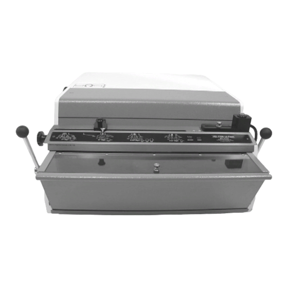
- Page 2 HD 7700 Setup & Operator Manual Issue 1 December, 01 Performance Design Inc. The Heavy Duty Ultima (HD 7700) electric punch has been designed to punch most any job that may pass through your bindery or office. No matter what type of binding you need to carry out, the HD 7700 can punch the job.
-
Page 3: Table Of Contents
Table of Contents HD 7700 PUNCH Topic: Page Number: 1) Important safety notice 2) Placing your machine in the proper location 3) Providing power to the machine 4) Die installation ♦ HD 7700 ♦ Extra Capacity Die ♦ Comb Die ♦... -
Page 4: Topic
Topic: Page Number: 12) Attaching OD 4400 Comb Opener Setup Instructions a) Determine the correct comb size b) Placing the comb onto the rake c) Setting the comb opener stop d) Placing the book onto the comb e) Margin settings Setup Illustrations Diagram 1 Punch (Setup) -
Page 5: Important Safety Notice
1) Important Safety Notice! Make sure you read this section very carefully! Learn to recognize this Safety Alert Symbol. The HD 7700 has been designed to provide a very high level of protection to an operator. Follow the guidelines below while installing, operating and maintaining your machine. -
Page 6: Die Installation
4) Die installation: ♦ HD 7700 Diagram 2 Make sure the machine is turned off before installing die. Install the die (1) by sliding it into the opening of the machine located on the right-hand side of the machine. Make sure the punch pin retainer assembly (2) slides into the slot of the pusher bar. -
Page 7: Removing Punch Pins
♦ Removing Punch Pins: Make sure the machine is turned off before removing the die. To remove a punch pin Diagram 3 from the die, disengage both quick change die handles and slide the die to the right until the die is completely removed from punch. Step 1. -
Page 8: Die Maintenance
♦ Die maintenance: The die will have to be removed before maintenance can be performed. Using the oil provided with the machine, squeeze the plastic bottle over the oil slot that runs the entire length of the die. Too much oil can run onto the paper being punched. -
Page 9: Punching Paper
6) Punching Paper: Diagram 5 Position the paper that has to be punched either to the left, right or on top of the machine. This is up to the individual operator. Remove some sheets (When punching acetate and heavier stock, punch less sheets) from the pile and slide it down vertically into the opening of the die. -
Page 10: Removing Paper Waste
7) Removing paper waste: Diagram 6 The paper waste is removed by pulling the paper waste drawer up and toward you. The drawer is located conveniently in the front of the punch. This drawer should be checked frequently. Look through the clear cover while punching and empty prior to filling up and spilling into machine. -
Page 11: Paper Jam
8) Paper Jam: Diagram 7 The HD 7700 uses a circuit board for controlling its cycle and has the ability to automatically reverse the punch pins to their starting position if too much acetate or paper was inserted. There are times when punching too much acetate, the punch pins may not reverse all the way out. - Page 12 Die list: This is a list of the most common dies manufactured by Performance Design. Special dies are available. Ask your dealer for more information. Drawings are to scale. (5mm) HD 7700 Issue 1 Page 11...
- Page 13 .125, .163, .201, .239 D 7700 Issue 1 Page 1...
- Page 14 Only qualified personnel should attempt to work on this equipment. The HD 7700 punch is a well-built, heavy duty punch and will give years of reliable service. Most of the problems are due to setup error. There is a circuit breaker located at the rear of the punch that can be reset by the customer if it should trip.
- Page 15 HD 7700 Electrical Schematic (115 volt AC) Electrical Shock Hazard HD 7700 Issue 1 Page 14...
-
Page 16: Combo Binding Station Od 3500
9) OD 3500 Combo binding station: Diagram 8 The combo binding station is a base unit that supports three different binding modules. Each module attaches in a matter of minutes. The attachment procedure will be located in the module instructional section of this manual or in the separate manual for the module. - Page 17 OD 4200 Wire closer The wire closer is capable of binding books up to 1-1/8” (28.6mm) thick. It uses wire sizes from 3/16” to 1-1/4”. It has an adjustable closing bar for the different size wires. Each end can be adjusted independently to obtain a perfect close. The unit attaches to the rear of the Combo binding station using four knobs.
-
Page 18: Attaching Od 4300 Coil Inserter
OD 4300 Coil Inserter 10) Installation Instructions: Diagram 9 Procedure to attach the coil inserter onto the combo binding station. Keep all clothing and jewelry away from rotating drive wheel. Power cord shall be certified for the country where the machine will be installed! ♦... -
Page 19: Setup Instructions
Setup Instructions: Diagram 10a, 10b, 10c, 10d & 10e Determine the correct coil size. Use a coil that is at least 3/32” (2.5mm) larger than the book thickness for coil sizes up to 3/4” (20mm). After 3/4”, use a coil size of at least 1/8” over the book size. -
Page 20: D) Adjusting The Mandrel Bracket
Adjusting the mandrel bracket. ♦ The mandrel assembly-adjustment knob (4) is located on the right side of the coil inserter. Move the mandrel bracket assembly toward the drive wheel for small mandrels and away from the drive wheel for the larger mandrels. Diagram 10a ♦... -
Page 21: G) Forward / Off / Reverse Switch
away from the machine, it acts as a support table (7b) for larger books. For books over 9/16”, it may be necessary at times to split the book in half using the table to support one half of the book, then finish the inserting of the coil. -
Page 22: H) Inserting A Coil
Inserting a coil. Place the coil on the mandrel by sliding the open end of the coil onto the beveled end of the mandrel. Turn the coil so it threads onto the mandrel post (9) and is in front of the drive wheel by one coil. Make sure the forward / reverse switch is in the forward position. -
Page 23: J) Cutting A Coil
the motor handle (10) until the drive wheel touches the coil. Try a few books and readjust if necessary. If the mandrel bracket is adjusted after the stop screw has been adjusted, it will be necessary to readjust the stop screw. Cutting a coil. - Page 24 Diagram 10f Only qualified personnel should attempt to work on this equipment. Most of the problems you may encounter are due to setup errors. There is one fuse located at the rear of the OD 4300 inserter that can be replaced by the customer.
- Page 25 Coil Inserter Module Electrical Schematic (115 volt AC) Electrical Shock Hazard NOTE: The motor is protected by a thermal overload located in the motor. It will reset automatically after the motor cools. This product has earned the UL Listing Mark and the UL Listing Mark for Canada.
-
Page 26: Attaching Od 4200 Wire Closer
OD 4200 Wire Closer 11) Installation Instructions: Diagram 11 Procedure to attach the wire closer onto the combo binding station. ♦ Place the closer module on the backside of the combo binding station so the closer adjustment knobs are facing the front of the punch and are pointing up. ♦... -
Page 27: A) Determine The Correct Wire Size
Setup Instructions: Diagram 12a, 12b, 12c & 12d a) Determine the correct wire size. Use the table below to determine the correct wire size for the book thickness. You can insert more sheets into the wire, but it may affect the appearance of your book. -
Page 28: C) Setting The Closing Bar Height
c) Setting the closing bar height. The closing bar is adjustable on each end allowing the operator to achieve a perfect close at each end of the book. Pull the handle on the closer all the way down and adjust both knobs (3) so the top edge (4) of the closing bar lines up with the line (5) next to the wire size you want to close. - Page 29 Diagram 12c Diagram 12d HD 7700 Issue 1 Page 28...
- Page 30 OD 4400 Comb Opener 12) Installation Instructions: Diagram 13 Procedure for attaching the comb opener onto the combo binding station. ♦ Place the comb opener module on the backside of the combo binding station so the narrow section of the comb opener is facing the front of the combo binding station.
-
Page 31: B) Placing The Comb Onto The Rake
a) Determine the correct comb size. Use the table below to determine the correct comb size for the book thickness. You can insert more sheets into the comb, but it may affect the appearance of your book. Covers are not included with the number of sheets column. -
Page 32: D) Placing The Book Onto The Comb
BOOK ON COMB COMB ON RAKE COMB OPENED Diagram 14 d) Placing the book onto the comb. Diagram 14 Place the holes of the book on the fingers of the comb. A slight rotating of the book will help guide the holes onto the comb. Return the opener handle to close the comb into the book.
Need help?
Do you have a question about the Onyx HD7000 and is the answer not in the manual?
Questions and answers