Table of Contents
Advertisement
Quick Links
F
ind out more
on the web
www.wiLburcurtis.com
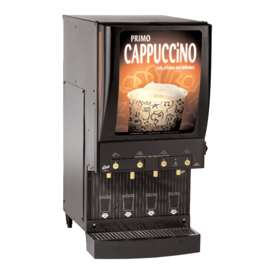
Models Included
u CAFE PC1
u CAFE PC1 WITH LIGHT BOX
u CAFE PC2
u CAFE PC2 WITH LIGHT BOX
u CAFE PC3
u CAFE PC3 ICED CAPPUC-
CINO
u CAFE PC3 WITH LIGHT BOX
u CAFE PC4
u CAFE PC4 WITH LIGHT BOX
WARNING HOT LIQUID,
Scalding may occur.
Avoid splashing.
CAUTION: Please use
this setup procedure
before attempting to use
this appliance. Failure to follow the
instructions can result in injury or the
voiding of the warranty.
CAUTION: DO NOT
connect this unit to hot
water. The inlet valve is
not rated for hot water.
WILBUR CURTIS COMPANY
Montebello, CA 90640
ISO 9001 REGISTERED
W
ilbur
Service Manual – CAFEPC
Important Safeguards/Conventions
This appliance is designed for commercial use. Any servicing other than cleaning and maintenance should be performed by an autho-
rized Wilbur Curtis service center.
• Do NOT immerse the unit in water or any other liquid
• To reduce the risk of fire or electric shock, do NOT open top panel. No user serviceable parts inside. Repair should be done
only by authorized service personnel.
• Keep hands and other items away from hot parts of unit during operation.
• Never clean with scouring powders or harsh implements.
Conventions
WARNINGS – To help avoid personal injury
Important Notes/Cautions – from the factory
Sanitation Requirements
Your Curtis ADS System is Factory Pre-Set and Ready to Go... Right from the Carton.
Following are the Factory Settings for your Primo Cappuccino Beverage System:
• Tank Temperature = 190°F
• Flavor Controls= Set at 50%
• Dispensing Mode Set for Manual Dispensing
Generally there will never be a reason to change your programming. However, should you need to make slight adjustments to meet your
dispensing needs, programming instructions are provided later in this manual.
System Requirements:
• Water Source 20 – 90 PSI (Minimum Flow Rate of 1 GPM)
• Electrical: See attached schematic for standard model or visit www.wilburcurtis.com for your model.
Equipment to be installed to comply with applicable federal, state, or local plumbing/electrical codes having jurisdiction.
SETUP STEPS
The unit should be level (left to right and front to back), located on a solid counter top. Connect a water line from the water filter to the
brewer. NOTE: Some type of water filtration device must be used to maintain a trouble-free operation. (In areas with extremely hard
water, we suggest that a sedimentary and taste & odor filter be installed.) This will prolong the life of your dispensing system and enhance
cappuccino product quality.
The National Sanitation Foundation requires the following water connection:
1. A quick disconnect or additional coiled tubing (at least 2x the depth of the unit) so that the machine can be moved for
Cleaning underneath.
2. In some areas an approved backflow prevention device may be required between the brewer and the water supply.
1. Connect a water line from your facility to the 1/4" flare water inlet fitting of the valve, behind the machine. Water volume going to the
machine should be stable. Use tubing sized sufficiently to provide a minimum flow rate of one gallon per minute.
2. Plug the power cord into an electrical outlet rated at 20A.
3. Switch on the toggle switch, behind the unit, that runs power to the components in the machine. The display window and Stop/Wash
light on the front door will activate and the heating tank will start to fill.
4. Water in the heating tank will require about ½ hour to reach operating temperature (factory setting of 190°F). At this time the Ready
LED will light.
5. Remove and fill the canisters with powdered cappuccino mixes.
OPERATION INSTRUCTIONS
1. Choose a flavor. Place your cup under the spout beneath the desired flavor.
2. Push and hold the dispensing button for this flavor.
3. Release the button when the cup is ¾ full.
FILL CANISTERS DAILY
1. Open the front door to access the coffee canisters.
2. The canisters must be removed from the unit for filling. Turn the product delivery
elbows upward.
3. Reposition the canisters on the machine, turning the product delivery elbows down-
ward and aligning the gear socket with the motor shaft.
For the Latest speciFications and inFormation go to www.wiLburcurtis.com
C
C
urtis
ompany
, i
.
nC
1
Advertisement
Table of Contents

Related Manuals for Curtis CAFE PC1


Summary of Contents for Curtis CAFE PC1
- Page 1 Important Notes/Cautions – from the factory u CAFE PC3 WITH LIGHT BOX u CAFE PC4 Sanitation Requirements u CAFE PC4 WITH LIGHT BOX Your Curtis ADS System is Factory Pre-Set and Ready to Go… Right from the Carton. WARNING HOT LIQUID, Following are the Factory Settings for your Primo Cappuccino Beverage System: Scalding may occur. • Tank Temperature = 190°F Avoid splashing.
- Page 2 Steps to Programming Your Curtis Cafe System is Factory Pre-Set for Optimum Performance. Usually this Does Not Change. WARNING HOT LIQUID, Scalding may occur. Avoid splashing. Place an empty container under the dispensing nozzles while programming. All programming is performed at the control panel (illustration, right). The STOP/WASH BUTTON has several func- tions. This button is used to stop a Portion Control dispense cycle. It is used to wash out the mixing and dispensing systems and it is used to enter programming functions. Product % Ratio This controls the amount of dry product that is metered from the hoppers. This can be programmed from 10% to 100% of the capacity of the dispensing system. By counting LED flashes you can determine the product % ratio currently set for this dispense button (see table). Number of Enter Program Mode –...
- Page 3 185ºF 190ºF 192ºF To Change Temperature. Release STOP/WASH button, then press and hold again. Each 194ºF quick flash equals 2ºF. Release STOP/WASH when desired temperature is reached. 196ºF 198ºF 200ºF 202ºF 204ºF To Set and Exit, press either of the PUSH buttons. ERROR CODES: Curtis Cafe systems contain various safety features in the electronic circuitry that shut down the functions of the unit in the event of a system failure. Error codes are signalled by the READY light blinking one of two patterns: WATER LEVEL PROBLEM 3 LONG AND 1 SHORT When observing this code on the switch panel, be aware there is a malfunction in the water level control system. TEMPERATURE SENSOR PROBLEM 3 LONG AND 2 SHORT Whenever this light pattern is seen flashing on the control panel you are experiencing a tank heating system failure. Flushing the Whipper Chambers CAUTION: Every three to four hours or more often if necessary flush the whipper chamber/dispensing system. DO NOT use A. Make sure power is ON.
- Page 4 3. Now turn the flow adjustment screw counter clockwise three [3] turns (or 1½ turns from the fully open position). 4. Replace the metal guard. 5. Install the valve on the tank, attaching wires and silicone tube. Press the valve fully into the fitting on the heating tank. Figure 2. Restrictor Closed. Dump valve, water flow adjustment: The Water flow is preset to ensure optimum mixing and proper chamber rinsing. The valves currently installed on your unit have been set at the factory and should not require adjusting. The factory flow rate setting is 8 oz. of water in 10 seconds (or 0.8 oz./sec.). Before mounting a whipper plate, place a dab of Whipper Plate Replacement food grade lubricant in the rear hole of the seal. Shaft seals should be replaced with the groved side facing outward. Replacing Film in Light Box 1. Turn OFF power by unplugging the power cord. 2. Open the front door and remove the six screws that attach the light box. 3. Pull off the light box assembly from the door. Detach at the hook at the top of the light box (illustra- tion, right item 1). 4. Take out old film, unhooking it from the bottom tabs and sliding it out of the frame. 5. Insert the new film, slide it into the frame and hook it under the tabs to secure it (see illustration below). 6. Return the light box to the front door. From inside the door, insert the six screws that were removed in step #2. 7. Close the front door and plug in the power cord. The light box should come on. 8. Check that the film lies flat and there is no light leaking from the edges. If okay, the Curtis CAFEPC unit is ready to use.
- Page 5 Illustrated Parts List VIEW SHOWN ROTATED...
- Page 6 PANEL, 4 BTN 4LED 6 PN CAFEPC3 (OLD UNIT) WC-37234 KIT, ADD-ON LIGHT BOX ASSY CAFE PC3 WC-39497 LABEL, ASSY CNTRL PNL & OUTER CAFE PC1 WC-37273 KIT, ADD-ON LIGHT BOX ASSY CAFE PC4 WC-39498 LABEL, ASSY CNTRL PNL & OUTER CAFE PC2...
- Page 7 Illustrated Parts List Light Box Option Electrical Diagram POWER SUPPLY 120VAC HYBRID CONTROL POWER MODULE LEGEND: .47MF CAPACITOR CAFEPC1 CAFEPC2 275VAC (BLK) (BLK) ALTERNATE TOGGLE SWITCH TRANSFORMER SPST 25A 125/250V WIRE HOOKUPS 30W LIGHT ASSY OPTIONAL RESET WHT or RED THERMOSTAT BALLAST SET AT 220°F...
- Page 8 Curtis equipment that have not been purchased from the Wilbur Curtis Company, Inc. The Wilbur Curtis Company will not accept any responsibility if the following conditions are not met. The warranty does not cover and is void under the following circumstances: 1) Improper operation of equipment: The equipment must be used for its designed and intended purpose and function.
Need help?
Do you have a question about the CAFE PC1 and is the answer not in the manual?
Questions and answers