
Related Manuals for Bang & Olufsen BeoVision 12-65 MK II


Summary of Contents for Bang & Olufsen BeoVision 12-65 MK II
- Page 1 BeoSystem 4 Type 9666 - 9670 BeoVision 12-65 Type 7953 - 7957 BeoVision 12-65 MK II Type 7958, 7964, 7967, 7977 - 7978 Installation Guide English - version 1.3 43.9 28.0 161.0 29.0 96.3 2014-06-17T08:05 v1-3-01 in Design...
- Page 2 Introduction Introduction The BeoSystem 4 is a highly advanced unit for controlling either flat screen monitors, such as BeoVision 12-65, or a projector. BeoSystem 4 connects to almost any source, plays most formats, controls surround sound and speakers in more rooms and can be operated e.g. by the Beo4 remote control.
- Page 3 How to use this installation guide How to use this installation guide Introduction This installation guide gives step by step instructions in how to install: How to use this installation guide - BeoSystem 4 connection panels - Placement and mains cable connection BeoSystem 4 connection panel - Installation scenarios Placement...
- Page 4 BeoSystem 4 connection panel BeoSystem 4 connection panel EU connection panel CTRL 1 CTRL 2 CTRL 3 PUC 3 A+B PL 1 PL 2 PL 3 CHIPSIDE CHIPSIDE 14/18V=0.4A 5V=50mA 12V=1.0A S/P-DIF COMMON INTERFACE SATELLITE AERIAL STAND 0,5A HDMI IN EXT IR PUC 1 PUC 2...
- Page 5 Placement - Wall mounting Placement The BeoSystem 4 can be mounted in various ways: - On a shelf or similar horizontal surface, e.g. in a cabinet - Wall mounted - Rack mounted Wall mounting - BeoSystem 4 can be mounted on a wall by adding the wall brackets, each using the existing screws. See also the installation guide enclosed in the packaging for the brackets.
- Page 6 Placement - Rack mounting Rack mounting The BeoSystem 4 can be mounted in a 19” rack by adding the brackets for rack mounting. The BeoSystem 4 can be placed with the cables to the front or hidden at the back side of the BeoSystem 4. See example in the below illustration. The brackets for rack mounting can be placed flush with the cabinet front/rear or displaced in order to have the cables in front of the BeoSystem 4 although behind the cabinet front frame.
- Page 7 Connecting mains cable Connecting mains cable Connect the mains cable plug into the mains socket of the BeoSystem 4 and mount the cable holder as shown.
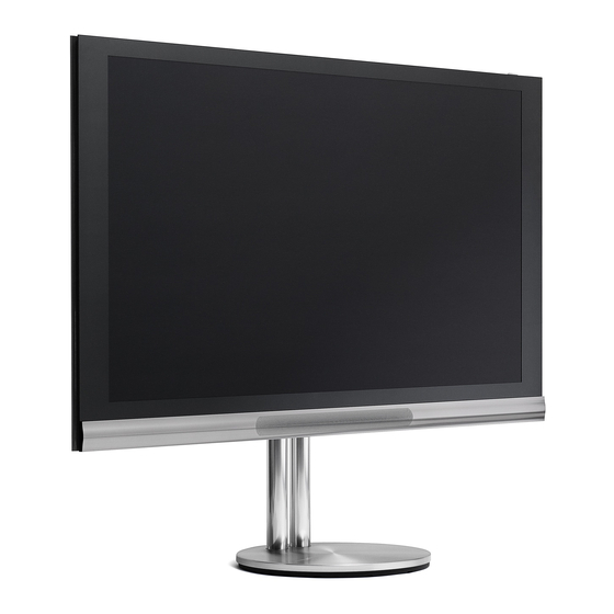
- Page 8 Lifting equipment The weight of the BeoVision 12-65 MK II is 81.4 kg / 179.2 lbs. Due to the heavy weight of the product, any moving or lifting of the product should be performed by qualified personnel – using the proper equipment.
- Page 9 Install BeoSystem 4 with BeoVision 12-65 Cabling The cabling between the BeoSystem 4 the BeoVision 12-65 consists of: Cable type Socket on BeoSystem 4 Socket on BeoVision 12-65 HDMI HDMI OUT HDMI IN Cat 7 CONTROL MONITOR CONTROL Cat 7 IR/AUTO CONTRAST IR OUT Cat 7...
- Page 10 Install BeoSystem 4 with 3 party TV display Install BeoSystem 4 with 3 party TV display Cabling The cabling between the BeoSystem 4 and a 3 party television consists of: Cable type Socket on BeoSystem 4 Socket on 3rd party TV HDMI HDMI OUT HDMI IN...
- Page 11 Extending cables Extending cables Cat 7 cables Cat 7 cables should never be extended. They must be run in the appropriate length from product to product, from wall outlet to distribution frame or from product to wall outlet. HDMI cables HDMI cables may be used up to 10 m / 33 ft.
- Page 12 Extending cables Cabling via wall outlets - hidden Living room Technical room BeoSystem 4 Cabinet / distribution frame 2xRJ45 2xRJ45 2xRJ45 2xRJ45 Network Link Cat 7 Power Link The cabling can run via wall outlets and is cross connected in the distribution frame in the technical room or alternative place following the principles as illustrated;...
- Page 13 Extending cables Direct cabling - visible Living room Technical room BeoSystem 4 Cat 7 Power Link The CAN cable can run directly between the BeoSystem 4 and the BeoVision 12-65 in case there is no wall outlets and distribution frame. The principle is shown in the simplified illustration above.
- Page 14 Extending cables HDMI and Control Cable using Atlona AT-HDTX-RSNET / AT-HDRX-RSNET Living room Technical room BeoSystem 4 Extender Cabinet / distribution frame Extender Network Link Cat 7 Power Link 2xRJ45 2xRJ45 2xRJ45 HDMI IR-cable RS232 Cabinet / distribution frame Connection panel for Floor Stand via Cat 7 BeoVision 12-65 and Junction Box...
- Page 15 Extending cables HDMI and Control Cable using Atlona AT-PRO3HDREC The example below is similar to that of the previous page; see page 14. The only difference is that an AT-PRO3HDREC is used instead of an AT- HDRX-RSNET. The AT-PRO3HDREC can be concealed in the connection panel of the BeoVision 12-65. BeoVision 12-65 Floor Stand via Cat 7 connection panel...
- Page 16 Extending cables HDMI and Control Cable using Atlona AT-HDTX-IR / AT-HDRX-IR Living room Technical room BeoSystem 4 Extender Cabinet / distribution frame Network Link Extender Cat 7 RJ45 2xRJ45 2xRJ45 Power Link IR-blaster HDMI IR-cable Cabinet / distribution frame CTRL 1 CTRL 2 CTRL 3 PUC 3 A+B PL 1...
- Page 17 Extending cables IR blaster cable - wire connections The illustrations show the connection of the wires in the captive screw connectors with the AT-HDTX-IR / AT-HDRX-IR from Atlona. Note: instructions in correct use of the captive screw connectors are given in the next section. Connection of IR blaster end of cable PWR IR Connection of RJ45 end of IR blaster cable...
- Page 18 Extending cables > Continued from previous page The below description is used when connecting to older televisions and when using the IR cable with optocoupler Part No.: 6271240. 6271240 6271233 Braided Shield (Bang & Olufsen Part No.: 6271240) (Bang & Olufsen Part No.: 6271233) White Cut off the Mini Jack 3.5 mm Stereo plug (marked: HDMI Receiver) of the IR cable with Optocoupler (Bang &...
- Page 19 Shortening IR-blaster cables - PUC cables Shortening IR-blaster cables - PUC cables The IR-blaster cable enclosed for PUC control with the products is often too long. It is good installation practice to shorten cables to get rid of excessive cable. IR blaster cable with 1 IR blaster has Bang &...
- Page 20 Screen measurement Screen measurement The easiest way to do the screen measurement is by having the BeoSystem 4 within 1.8 m/6 ft distance from the BeoVision 12-65 if at all possible. If this is not possible, see “Distance between BeoSystem 4 and BeoVision 12-65” below. Screen measurement - introduction The BeoSystem 4 requires some measurements to be made to match it to the BeoVision display it is connected to.
- Page 21 Screen measurement Screen measurement - start menu The following is a step-by-step instruction of the Screen measurement cycle. - Initiate the screen measurement cycle automatically or via the Customer Service menu; see page The following is shown: The SCREEN MEASUREMENT dialogue gives a status as follows: SCREEN NOT MEASURED / MEASURED (depending on if a screen measurement has been completed).
- Page 22 Screen measurement - Measure Screen MEASURE SCREEN - sequence - Select MEASURE SCREEN and press the Centre button. √ The following is shown: ROTATE THE DIFFUSER AWAY FROM THE LENS BEFORE STARTING AND PLACE SENSOR ON THE GREEN SQUARE NOT OVERLAPPING THE RED AREA.
- Page 23 Screen measurement - Measure Screen Start measurement - Follow the instructions from the previous page: - Turn the diffuser away from the lens; see illustration. - Place the elastic strap around the BeoVision 12-65 and the measurement device as shown in the illustration. The elastic strap must be tightened using the plastic buckle.
- Page 24 Screen measurement - Measure Screen MEASURE LIGHT SENSOR - sequence - With the MEASURE LIGHT SENSOR function highlighted, press the Centre button to start the measurement. The following instructions are shown - follow these: √ PREPARATION: ROTATE THE DIFFUSER OVER THE LENS BEFORE STARTING, REFER TO THE DRAWINGS IN THE INSTALLATION GUIDE...
- Page 25 Screen measurement - Measure sensor step 1 of 4 Step 1 of 4 Note: See recommendations regarding ambient light conditions on the previous page. The recommendations are important to be followed for a succesful measurement as described in the next 4 steps. An error message will be given at step 4 if conditions are not satisfactory.
- Page 26 Screen measurement - Measure sensor step 2 of 4 Step 2 of 4 For this measurement, the measurement device is oriented as seen in the illustration. The measurement device is held by hand. The following instructions are shown - follow these (see the illustration): STEP 2 OF 4: HOLD/ATTACH THE MEASURING DEVICE AGAINST THE SCREEN’S...
- Page 27 Screen measurement - Measure sensor step 3 of 4 Step 3 of 4 For this measurement, the measurement device is oriented as seen in the illustration. The measurement device is held by hand. The following instructions are shown - follow these (see the illustration): STEP 3 OF 4: HOLD/ATTACH THE MEASURING DEVICE AGAINST THE SCREEN’S...
- Page 28 Screen measurement - Measure sensor step 4 of 4 Step 4 of 4 Note: Do not disconnect the measurement device until step 4 has been completed as well. The following instructions are shown - follow these (see the illustration): STEP 4 OF 4: COVER THE TV’S LIGHT SENSOR ON Ambient light sensor THE UPPER RIGHT HAND CORNER OF...
- Page 29 Projector Screen - general information Projector Screen - general information Screen choices Screen Size General considerations regarding projector distance and viewing distance are mentioned in this paragraph. More details are found on the following pages. The screen size depends on the projector and especially the projector lens chosen. The projector lens has a Throw Ratio of e.g. 1.75 (min.) to 2.48 (max.) that multiplied by the width of the screen gives the Throw Distance.
- Page 30 Projector placement Projector placement In the following sections guidelines for finding the values for best placement of the projector is presented. Also see the projector manual and observe the lens choices possible. Projector placement The following must be decided for: a screen size taking the viewing distance and the throw distance into consideration. Once the projector and the screen are placed, the fine adjustments of the picture can be made.
- Page 31 Projector placement Room layout Guide with dimensions for recommended setup - Measuring the room Measure the dimensions of the room, depth, height and width. If the room is very big, measure the part of the room where the setup is to be placed, mark up the edges and measure.
- Page 32 Projector placement Throw distance The projector’s throw distance is the width of the projected image times throw ratio. The throw distance is measured from lens to screen. (Y = X × Throw ratio). The throw ratio varies depending on projector type and the lens chosen.
- Page 33 Projector placement Bracket height The length of D, depends on how far the black drop is on the screen. The illustration below tells you how to find the correct height. Note: The vertical centre line of the lens is D + Vertical Lens Offset.
- Page 34 Speaker placement Speaker placement Front speaker corner placement If the front speakers should be placed in the corners of the room, make sure that the distance to each wall are not the same. (Y = square root of 2 times X) Note: Set loudspeaker position switch according to placement;...
- Page 35 Speaker placement Surround sound, 5.1 speaker placement The illustration above is the optimum setup, which should be copied as much as possible, if the customer is to experience the best possible movie viewing. The subwoofer should be placed between the front speakers, but not centred in the room.
- Page 36 Speaker placement Surround sound, 7.1 speaker placement The illustration above is the optimum setup, which should be copied as much as possible, if the customer is to experience the best possible movie viewing. This illustration shows the recommended setup. The subwoofer should be placed between the front speakers, but not centred in the room.
- Page 37 Speaker placement 5.1 Setup This system has six channels: five full-range channels, and a low-frequency effects channel, usually expressed as subwoofer. 7.1 Setup The most advanced home theatre systems feature seven full-range channels that take full advantage of e.g. Dolby Digital sound tracks and DTS Digital Surround matrix-surround decoding technology.
- Page 38 Customer Service Menu Customer Service Menu PUC VERSION CUSTOMER SERVICE SW VERSION SOUND ADJUSTMENT (The menu structure shown is depending on Sony PS3 RE-BL 2.00a [ON / OFF] SW VERSIONS SVN REVISION 1.0.4.31499 SOUND MODULATION LIMIT Atlona AT-ProHD88M 2.00a product and SW build and consequently the PUC VERSIONS BBE REVISION 1.2.1...
- Page 39 Customer Service Menu Customer Service Menu The Customer Service Menu gives the opportunity to customise and optimise features in the product that normally require the aid from the dealer or service centre. It may also be used to give the Service Centre the basic information about the product directly on screen and not by reading a label on the back of the product.
- Page 40 Customer Service Menu HW VERSIONS This submenu shows the hardware version for the different circuit boards or modules in the system. These values are read-only and cannot be modified through the menu. The following options are presented under HW versions: - Product variant - Tuner variant - Stand variant (if used)
- Page 41 Customer Service Menu SETTINGS CLOCK CLOCK ON/OFF: Factory setting is ON. The de-activation of the clock only applies to the HW clock and not if the clock is present via Internet or DVB. Missing clock function will make software and PUC update impossible. CLOCK TIMEOUT CLOCK TIMEOUT sets the amount of seconds that should pass before the clock is removed from the status display/screen.
- Page 42 Customer Service Menu REROUTE LIGHT/CONTROL To enable or disable - YES/NO light and control commands being sent to a Home Automation (HA) interface box. B&O NETWORK DOMAIN For future use. Provides the possibility to define different zones or product groups. HbbTV To enable or disable - ON/OFF - the HbbTV function.
- Page 43 Customer Service Menu RESET CI+ AUTHENTICATIONS - RESET CI+ AUTHENTICATION: If experiencing problems with the CI+ Authentication, the customer can be advised to reset CI+ data. When activating this menu line you see: RESET ALL CI+ AUTHENTICATIONS YES/NO. PICTURE ADJUSTMENTS AFTER IMAGE ERASER Activates a black screen, where a white horizontal bar scrolls over the screen.
- Page 44 Customer Service Menu SIGNAL INFORMATION INPUT - VFREQ is the vertical frequency in Hertz. - HTOTAL is the total number of horizontal pixels including blanking period. (Not present on internal sources). - VTOTAL is the total number of vertical lines including blanking period. (Not present on internal sources). - RESOLUTION is the number of visible horizontal and vertical pixels.
- Page 45 Customer Service Menu SCENE SETUP Activating this menu leads you to a subset of parameters that you can set up in connection with especially a projector setup. Menu’s will only be shown for products supporting “Scene Setup”. OPEN COLLECTORS SETUP - Open Collectors requires external power supply and can either be stated in low or high impedance state (sinking current, not outputting a voltage high or low).
- Page 46 Customer Service Menu CINEMA OFF Also in a single output setup it will be relevant to setup the different timers to secure a smooth shut down of the cinema experience. - CONTROL TIMER 1 can be changed. It defines the time from the user presses Standby in Projector mode until Control Timer 1 port is deactivated. - CONTROL TIMER 2 can be changed.
- Page 47 Customer Service Menu CINEMASCOPE: - CINEMASCOPE ON/OFF is used to control a motorised lens in front of the projector. If setting this to ON, the lens will be activated when entering one of the two special cinemascope formats. BtB is a menu point bringing you to a submenu where you can activate/deactivate the BtB functionality if and only if you are authorised to do so (Enterprise authorized staff only).
- Page 48 Connecting external sources Connecting external sources Internet ISP Router LAN Switch CTRL 1 CTRL 2 CTRL 3 PUC 3 A+B PL 1 PL 2 PL 3 CHIPSIDE CHIPSIDE Cat 7 14/18V=0.4A 5V=50mA 12V=1.0A S/P-DIF HDMI IN SATELLITE AERIAL COMMON INTERFACE STAND 0,5A IR-blaster...
- Page 49 Scene setup Scene setup - Open Collector setup To use scene setup the BeoSystem 4 must be set in Quick Start mode, that is periods where the product will switch On within seconds, and is consequently not in Standby mode. Quick-Start Timers are set as follows: press MENU >...
- Page 50 Scene setup CONTROL TIMERS If a Control Timer is chosen (above) the menu in the illustration to the right will be shown, CONTROL TIMERS CINEMA ON: CONTROL TIMER 1 If the Control Timer is to be set manually do the following: CONTROL TIMER 2 CONTROL TIMER 3 - Select CONTROL TIMERS >...
- Page 51 Scene setup Additional timer settings Additionally to the CONTROL TIMERS, the WARM UP TIME and COOL DOWN TIME must be set. Note: The values must be equal to or higher than the highest of the CONTROL TIMER values set for CINEMA ON or CINEMA OFF respectively. If that condition is not fulfilled, it will not be possible to store the entered values.
- Page 52 Video Output formats HDMI OUT Video Output formats HDMI OUT BeoSystem 4 (Displays marked with grey will be supported in future software; timing for support will be announced later). BeoSystem 4 combined with Vert. Freq. BeoSystem 4 BeoSystem 4 Video Output 3D formats BeoVision 4 / BeoVision 12 versions Video Output Formats BV4-65 MK III FHD...
- Page 53 Video Output formats HDMI OUT BeoVision 12-65 MK II Possible Display support to choose Generic 1920 × 1080p Projectors supported by Bang & Olufsen The below mentioned projectors are supported by PUC and standard settings. Samsung SP-A900B SIM2 Crystal 35 Lumis 3D-S Nero 3D-1 See ServiceTool or BeoWise for newest list of projectors.
- Page 54 Video Input formats Video Input formats Name of Type of signal Vert. Freq. No. of lines + scan Aspect Ratio Source Pixel Clock Supported Video Input Format (UseCase) “active” (“total”) Resolution Features (full frame) CVBS-576i-4:3 Composite 50 Hz 576i (625i) 720 x 576 13.5 MHz min.
- Page 55 Video Input formats > Continued from Vision Clear Formats above are the formats we guarantee with excellent picture and format handling. previous page Aspect Ratio can be signalled in the following ways: CVBS and RGBY: pin 8 in Scart; YPbPr and RGBHV: not possible; TMDS: in AVI-infoframe. Estimated resolution for analogue sources.
- Page 56 Outer dimensions Outer dimensions BeoVision 12-65 with Floor Stand 1610 mm / 63.4” 87 mm / 3.4” 6 mm / 0.24” 60 mm / 2.36” 36 mm / 1.42” 14 mm / 0.55” 143 mm / 5.63” 47 mm / 1.9” 106 mm / 4.17”...
- Page 57 Outer dimensions BeoVision 12-65 with Wall Bracket 117 mm / 4.21” 58 mm / 2.28” 6 mm / 0.24” Adjustable for parallel to wall 87 mm / 3.4” 87 mm / 3.4” 50 mm / 1.97” 1610 mm / 63.4” 64 mm / 2.52”...
- Page 58 Outer dimensions Wall bracket and TV dimensions Use the correct size and type of screws and wall anchors – taking into account the construction and condition of the wall. Use six round-headed screws and wall anchors, three in each side – each screw with a minimum load rating of 30 kg (66 lbs). Note: If mounted on a gypsum wall (also known as drywall or wallboard), the wall bracket must be fastened to a vertical stud.
- Page 59 Cables Cables The table below shows all cables currently available for BeoSystem 4. These cables are custom made for BeoSystem 4 and can also be found in the Accessory Catalogue under “CRM and Ordering System” in the Retail System. Type Part No.
- Page 60 Cables Cat 7 cable Cat 7 cables should never be extended. They must run in the appropriate length from product to product, from wall outlet to distribution frame or from product to wall outlet. HDMI cables HDMI cables may be used up to 10 m / 33 ft. When longer HDMI cables are needed they must be of the active type or an HDMI extender may be used (e.g.
-
Page 61: Cable Information
Cable information Cable information Network Link cables Network Link Product Cable in cable reels, Ø 6.0 mm / 0.24”, S/FTP, Cat 7/Class F, 8 wires + braided shield Network Link Product Cable, also used as patch cables in Network Link cabinet. Package size: 1 piece Colour Description... - Page 62 Cable information Network Link Installation Cable in cable reels - for self mounting, Ø 8.0 mm, S/FTP, Cat 7/Class F, 8 wires + braided shield Cable is used for in-wall installation. May be used as LAN cable. White/Orange Orange White/Green Green White/Blue Blue...
- Page 63 Cable information Power Link cables MKIII MKIII Power Link cable - general information Power Link cable exists in many variants. Three variants can be ordered at present: Shields from wires without - The Ø 5.0 mm / 0.2” cable (with 6 wires, of which 2 pairs are foiled and the insulation entire cable has a braided shield),.
- Page 64 Cable information Power Link Product Cable with plugs, Ø 5.0 mm, S/FTP, 6 wires + braided shield These cables include the wire for display data - double shielded - twisted pair. Based on the cable: white, 6250031. Package size: 1 piece Power Link - Product Cable Ø...
- Page 65 Cable information Power Link Product Cable with plugs, Ø 2.5 mm, FTP, 4 wires + braided shield These cables have no wire for data display and are marked with indicating MK III. Power Link - Product Cable Ø 2.5 mm / 0.1” - RJ45 to RJ45 Yellow Colour Description...
- Page 66 Cable information Power Link cables in cable reels Power Link Installation Cable in cable reels - for self mounting, Ø 5.0 mm, S/FTP/UTP, 6 wires + braided shield Yellow White/Brown White/Green Green Brown Braided shield White Part No. Length Connector Colour 6250017 300 m /...
- Page 67 Cable information IR solutions IR-eye with Autocontrast Part No. Description pcs. per package White/Blue (BtB Signal) 8089000 IR-eye with autocontrast 6271026 Choose a Network Link Product Brown (Light) 6271027 Cable or make one using a White/Brown (IR Data) 6271028 Network Link Installation Cable 6250027 - up to 100 m / 328 ft;...
- Page 68 Cable information IR-eye without Autocontrast BeoSystem 4 (using Network Link Product Cable) Part No. Description pcs. per package 8087030 IR-eye without autocontrast 6271026 Choose a Network Link Product 6271027 Cable or make one using 6271028 Network Link Installation Cable 6250027 - up to 100 m/ 328 ft;...
- Page 69 Cable information Open Collector solutions The Open Collector socket terminals of the BeoSystem 4 are used as follows: PUC 1, Pin 2 = Open Collector 1, and Pin 3 = Open Collector 2; see also page PUC 2, Pin 2 = Open Collector 3, and Pin 3 = Open Collector 4; see also page Network Link Product Cable - direct mounting Colour...
- Page 70 Cable information HDMI plug dimensions 20mm 34.8mm Cables used between BeoSystem 4 and BeoVision 4 RS232 cable - RJ45 to DSUB9 female RS232 cable, RJ45 - DSUB9 female, BeoSystem 4 to BeoVision 4-65/85/103 (Bang & Olufsen Part No’s: 6278725 / 6278726 / 6278727). Colour Description Colour...
- Page 71 Cable Information Cables used when replacing BeoSystem 3 with BeoSystem 4 In cases, where a BeoSystem 3 is replaced with BeoSystem 4, the RS232 cable and the IR cable is often run in a conduit or similarly hidden. The easiest way to connect to the BeoSystem 4 and keep the cables already installed is done by adding an adapter cable. See relevant combinations below.
- Page 72 Wiring diagram - external cables Wiring diagram - external cables BeoSystem 4 - BeoVision 12 RJ45 6271023, 6271024, 6271025, RJ45 6271026, 6271027, 6271028 IR/AUTO CONTRAST P310 > > 5V_EXT_IR 5V IR > > ON_LED ON_LED BeoSystem 4 > > STB_LED STB_LED GNDA <...
- Page 73 > > PL6_GNDA PL_GND > > PL6_ON_CON PL_ON PL_UP > > PL6_R_CON PL_R PL6_GNDA PL_GNDA > > PL6_L_CON PL_L Wiring diagram - external cables BeoSystem 4 - BeoVision 2-103 MKII, BeoVision 4-85 6271244, 6271245, RJ45 Microfit 6271246 IR/AUTO CONTRAST P310 >...
- Page 74 > HDMI_TXout_C_DN PL_GND >< CEC_TXout PL_ON > HDMI_TXout_DSCL PL_R >< HDMI_TXout_DSDA PL_GNDA PL_L > HDMI_5V_TX Wiring diagram - external cables < HDMI_TXout_HPD BeoSystem 4 - BeoVision 2-103 MKI, BeoVision 4-65 MK III Microfit 6271244, 6271245, RJ45 Microfit 8/8pins 6271246 P310 IR/AUTO CONTRAST >...
- Page 75 Wiring diagram - external cables BeoSystem 4 - 3 party TV RJ45 6271023, 6271024, 6271025, 5/5pins 6271026, 6271027, 6271028 IR/AUTO CONTRAST P310 > 5V_EXT_IR 5V IR IR receiver ON_LED ON_LED < STB_LED IR-OUTPUT without STB_LED > GNDA autocontrast BtB_3P_IR_IN_N BtB IR GNDA <...
- Page 76 Connection specifications Connection specifications Mains To see the different types of mains leads, see exploded view in the Retail Ordering System inlet Live Neutral Stand connector 12V = 1.0A MicroFit 4-pin Pin 1 CANL_C Negative CAN bus signal Pin 2 GND_STAND Ground for stand Pin 3 CANH_C Positive CAN bus signal...
- Page 77 Connection specification 9-pin Mini-DIN-Shielded AV IN Pin 1 Pin 2 Pin 3 Pin 4 CVBS Pin 5 Pin 6 1-AVL Pin 7 Audio L Pin 8 Pin 9 Audio R Case Case HDMI Input: 5 x Input Pin 1 TMDS. Data 2 + Pin 2 TMDS.
- Page 78 Connection specification Home integration primary PUC 1 A+B / CTRL 4 Data GND Pin 1 (chassis) *Pin 2 Open collector (out 1) 1 2 3 4 5 6 7 8 *Pin 3 Open collector (out 2) Pin 4 Pin 5 IR-blaster current PUC 1A (PUC 1) Pin 6 Pin 7...
- Page 79 Connection specification CTRL 1 USB-B Pin 1 USB power sense Data GND Pin 2 Not used Pin 3 Not used (chassis) 1 2 3 4 5 6 7 8 Pin 4 Pin 5 USB D – Pin 6 Pin 7 USB D + Pin 8 Shield...
- Page 80 Connection specification RS232 MONITOR CONTROL Pin 1 Pin 2 EXT_RS232_RX Data GND Pin 3 EXT_RS232_TX (chassis) 1 2 3 4 5 6 7 8 Pin 4 Pin 5 Pin 6 Pin 7 Pin 8 Shield Data GND IR/AUTO CONTRAST Room Awareness / IR-sensor Pin 1 Data GND Pin 2...
- Page 81 Table of Contents Table of Contents Table of Contents Introduction Introduction ..................2 How to use this installation guide How to use this installation guide ............3 BeoSystem 4 connection panel BeoSystem 4 connection panel ............4 Placement Placement ..................... 5 Connecting mains cable Connecting mains cable ...............
Need help?
Do you have a question about the BeoVision 12-65 MK II and is the answer not in the manual?
Questions and answers