
Subscribe to Our Youtube Channel
Related Manuals for Raymarine CAM200IP


Summary of Contents for Raymarine CAM200IP
- Page 1 CAM200IP / CAM210IP INSTALLATION INSTRUCTIONS English (EN) Date: 04-2016 Document number: 87232-3 © 2016 Raymarine UK Limited...
- Page 3 Software updates Important: Check the Raymarine website for the latest software releases for your product. www.raymarine.com/software Product handbooks The latest versions of all English and translated handbooks are available to download in PDF format from the website www.raymarine.com.
-
Page 5: Table Of Contents
8.4 Resetting the camera ........... 42 Certified Installation ........... 7 Chapter 9 Technical support ......43 Power Over Ethernet (PoE) ........7 9.1 Raymarine product support and servicing ....44 Water ingress ............7 Chapter 10 Technical specification....45 Disclaimer ..............8 EMC installation guidelines ........ - Page 6 CAM200IP / CAM210IP...
-
Page 7: Chapter 1 Important Information
Contact your Raymarine dealer for further details, and refer to the separate warranty document packed with your product. Power Over Ethernet (PoE) -
Page 8: Disclaimer
Disclaimer correct EMC performance. If ferrites are supplied separately to the cables (i.e. not pre-fitted), you Raymarine does not warrant that this product is must fit the supplied ferrites, using the supplied error-free or that it is compatible with products instructions. -
Page 9: Imo And Solas
To the best of our knowledge, the information in this document was correct at the time it was produced. However, Raymarine cannot accept liability for any inaccuracies or omissions it may contain. In addition, our policy of continuous product improvement may change specifications without notice. - Page 10 CAM200IP / CAM210IP...
-
Page 11: Chapter 2 Document And Product Information
Chapter 2: Document and product information Chapter contents • 2.1 Document information on page 12 • 2.2 Product overview on page 13 Document and product information... -
Page 12: Document Information
For detailed operation instructions for your product, This document contains important information refer to the documentation that accompanies your related to the installation of your Raymarine product. display. The document includes information to help you: • plan your installation and ensure you have all the necessary equipment;... -
Page 13: Product Overview
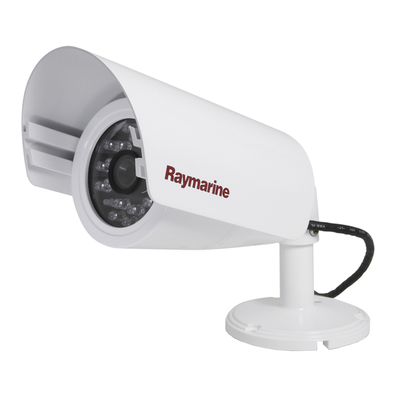
The camera has the following features: • 2 mega pixel 1/2.8" SONY progressive scan CAM200IP CMOS image sensor for excellent image quality The CAM200IP is an Infrared illuminated (I ) bullet IP (Exmor) camera with both day and night vision. In conjunction •... - Page 14 CAM200IP / CAM210IP...
-
Page 15: Chapter 3 Planning The Installation
Chapter 3: Planning the installation Chapter contents • 3.1 Installation checklist on page 16 • 3.2 Compatible multifunction displays on page 16 • 3.3 Parts supplied on page 17 • 3.4 Tools required on page 18 • 3.5 Typical systems on page 18 •... -
Page 16: Installation Checklist
3.1 Installation checklist 3.2 Compatible multifunction displays Installation includes the following activities: This product is compatible with the following LightHouse powered Raymarine multifunction Installation Task displays. Plan your system. • a Series, c Series, e Series, eS Series. Obtain all required equipment and tools. -
Page 17: Parts Supplied
3.3 Parts supplied Item Description Quantity Hex wrench (Allen key) CAM200IP The following items are supplied with your product. Item Description Quantity Waterproof RJ45 coupler IP camera (Includes a 1 m (39.4 in) ethernet and power pigtail cable) Note: To connect the camera to a compatible... -
Page 18: Tools Required
4.4 Power connection section. • Multiple camera system: Note: * The appropriate drill bit size is dependent You can use a Raymarine network switch to on the thickness and material of the mounting connect multiple cameras to a single MFD. Each surface. -
Page 19: Warnings And Cautions
3.6 Warnings and cautions 3.7 General location requirements Important considerations when choosing a suitable Important: Before proceeding, ensure that you location for your product. have read and understood the warnings and cautions provided in the Chapter 1 Important This product is suitable for mounting below decks. information section of this document. -
Page 20: Pan And Tilt
90°. Note: Pan and tilt angle adjustment is a mechanical procedure, performed by physically adjusting the camera’s position on its base. mm (3.5 in.) 174. 0 mm (6.9 in.) D13479-1 CAM200IP / CAM210IP... -
Page 21: Chapter 4 Cables And Connections
Chapter 4: Cables and connections Chapter contents • 4.1 General cabling guidance on page 22 • 4.2 Connections overview on page 23 • 4.3 Power options on page 23 • 4.4 Power connection on page 24 • 4.5 Network connection on page 26 Cables and connections... -
Page 22: General Cabling Guidance
Ensure that all data cables are properly shielded that the cable shielding is intact (e.g. hasn’t been • Ensure that any non-Raymarine cables are of the scraped off by being squeezed through a tight area). correct quality and gauge. For example, longer power cable runs may require larger wire gauges to minimize voltage drop along the run. -
Page 23: Connections Overview
Type Connects to: cables Either: RJ45 • RayNet A Network • Direct connection to a Raymarine gS Series network coupler and MFD (only one cable is required to carry both / or RayNet data and power signals), or • Multifunc-... -
Page 24: Power Connection
Camera’s power cable (Connection not required The PSE will always allocate the maximum power as camera is being supplied PoE by the MFD.) based on the classification of the PD. RayNet to SeaTalk adaptor cable (not supplied) CAM200IP / CAM210IP... - Page 25 • The power cable for each unit in your system should be run as a separate, single length of 2-wire cable from the unit to the vessel's battery or distribution panel. • Raymarine recommends a minimum wire gauge of 18AWG (0.82 mm ) for any length of cable extension.
-
Page 26: Network Connection
Alternatively a PoE injector could be More information used to power the camera. Raymarine recommends that best practice is observed in all vessel electrical installations, as detailed in the following standards: • BMEA Code of Practice for Electrical and Electronic Installations in Boats •... - Page 27 Multiple camera’s can be networked together using an network switch or router. 12 v dc + 12 v dc - D13095-1 Item Description Raymarine network switch IP camera RayNet to SeaTalk adaptor cable (not supplied) Waterproof RJ45 ethernet coupler (R32142) (supplied) Camera’s ethernet cable Camera’s power cable...
- Page 28 CAM200IP / CAM210IP...
-
Page 29: Chapter 5 Mounting
Chapter 5: Mounting Chapter contents • 5.1 Mounting the unit on page 30 Mounting... -
Page 30: Mounting The Unit
12. Lock the camera’s position by tightening the grub screws in the camera’s base, using the supplied Allen key. 13. CAM200IP only: clip the sun cover onto the D13096-1 camera, ensuring it does not overhang the front CAM210IP of the camera by more than 10 mm (0.39 in.). -
Page 31: Chapter 6 Operation
Chapter 6: Operation Chapter contents • 6.1 Operation instructions on page 32 • 6.2 Web browser interface on page 32 • 6.3 Reverse video and video flip on page 35 • 6.4 Resetting the camera to factory defaults on page 35 Operation... -
Page 32: Operation Instructions
Chapter 4 Cables and connections for details. 1. Click Start. 2. Click Control Panel. 3. Click System and Security. 4. Click Windows Firewall. 5. Click Allow a program or feature through Windows Firewall. 6. Scroll down the list to Network Discovery. CAM200IP / CAM210IP... - Page 33 7. Place a tick in the box for the type of network that the camera is on (this is usually Public). 8. Click OK. 9. From the Control Panel click Network and 2. Double-click a camera icon to open the web Internet.
- Page 34 Note: If you do not see the camera feed, make sure your computer has the latest version of Adobe Flash Player (Chrome, Firefox Internet Explorer and Safari) or ActiveX (Internet Explorer only) installed. After installing restart your browser and reconnect to the camera. CAM200IP / CAM210IP...
-
Page 35: Reverse Video And Video Flip
6.3 Reverse video and video flip 6.4 Resetting the camera to factory defaults The video feed can be reversed (mirror image), flipped upside down or reversed and flipped Follow the steps below to reset your camera’s depending on your installation. settings to their factory default values. - Page 36 CAM200IP / CAM210IP...
-
Page 37: Chapter 7 Maintenance
Chapter 7: Maintenance Chapter contents • 7.1 Routine checks on page 38 • 7.2 Unit cleaning instructions on page 38 Maintenance... -
Page 38: Routine Checks
This product contains high voltage. Adjustments require specialized service procedures and tools only available to qualified service technicians. There are no user serviceable parts or adjustments. The operator should never remove the cover or attempt to service the product. CAM200IP / CAM210IP... -
Page 39: Chapter 8 System Checks And Troubleshooting
Chapter 8: System checks and troubleshooting Chapter contents • 8.1 Troubleshooting on page 40 • 8.2 LED status on page 40 • 8.3 IP camera troubleshooting on page 41 • 8.4 Resetting the camera on page 42 System checks and troubleshooting... -
Page 40: Troubleshooting
LED sequence LED color State installations. Solid Red Power On All Raymarine products are, prior to packing and shipping, subjected to comprehensive test and quality assurance programs. However, if you Solid Green Network experience problems with the operation of your... -
Page 41: Ip Camera Troubleshooting
8.3 IP camera troubleshooting Problem Possible Solutions Camera does not power on. Power over Ethernet (PoE) connection • Ensure that the ethernet cable is connected correctly and that connections are secure. • Ensure you are not using a crossover coupler or cable as they are not appropriate for PoE applications. -
Page 42: Resetting The Camera
The camera’s web interface can be accessed when connected to a web-enabled device such as a PC. Please refer to 6.4 Resetting the camera to factory defaults for details. CAM200IP / CAM210IP... -
Page 43: Chapter 9 Technical Support
Chapter 9: Technical support Chapter contents • 9.1 Raymarine product support and servicing on page 44 Technical support... -
Page 44: Raymarine Product Support And Servicing
Servicing and warranty 3614 905 Raymarine offers dedicated service departments for Sweden support.se@raymarine.com warranty, service, and repairs. (0)317 (Raymarine subsidiary) Don’t forget to visit the Raymarine website to 633 670 register your product for extended warranty benefits: Finland +358 support.fi@raymarine.com http://www.raymarine.co.uk/display/?id=788. (0)207... -
Page 45: Chapter 10 Technical Specification
Chapter 10: Technical specification Chapter contents • 10.1 Technical specification on page 46 Technical specification... -
Page 46: Technical Specification
1280 x 720 default filter changer (supporting up to 1920 x Total pixels 1952(H) x 1116(V) 2.18 Mega 1080 (FHD) pixel Video streaming Supports multi streaming with Effect pixels 1944(H) x 1104(V) 2.14 Mega H.264, MJPEG pixel CAM200IP / CAM210IP... - Page 47 Minimum illumination 0 Lux (IR LEDs On) Distance 20 m (65.6 ft.) (20 LEDs) Lens 6 mm Mega pixel board lens Video specification Compression H.264 High Profile @ level 4.0, Motion JPEG Resolutions 1280 x 720 default (supporting up to 1920 x 1080 (FHD) Video streaming Supports multi streaming with...
- Page 48 CAM200IP / CAM210IP...
-
Page 49: Chapter 11 Spares And Accessories
Chapter 11: Spares and accessories Chapter contents • 11.1 Network hardware on page 50 • 11.2 RayNet to RJ45 adapter cables on page 51 • 11.3 Network cable connector types on page 52 • 11.4 RayNet to RayNet cables and connectors on page 53 Spares and accessories... -
Page 50: Network Hardware
• Enables the connection of RJ45 SeaTalk devices to a HS5 RayNet network switch (in conjunction with suitable adapter cables). • Enables 2 RJ45 SeaTalk cables to be connected together to extend the length of the cabling. Recommended for external installations. CAM200IP / CAM210IP... -
Page 51: Raynet To Rj45 Adapter Cables
• E55051 (10 m). • A62135 (15 m). • E55052 (20 m). Adapter cable with a RayNet (female) Directly connect a Raymarine radar scanner with an RJ45 socket on one end, and a waterproof SeaTalk (male) cable to a RayNet network switch (e.g. -
Page 52: Network Cable Connector Types
11.3 Network cable connector types There are 2 types of network cable connector — RayNet, and RJ45 SeaTalk RJ45 SeaTalk connector. RayNet connector. CAM200IP / CAM210IP... -
Page 53: Raynet To Raynet Cables And Connectors
11.4 RayNet to RayNet cables and connectors 400 mm (1.3 ft) 2 m (6.56 ft) 5 m (16.4 ft) 10 m (32.8 ft) 20 m (65.6 ft) A80161 A62361 A80005 A62362 A80006 R70014 A80262 100 mm (3.9 in) A80162 D13160-1 Description Typical use Quantity... - Page 54 CAM200IP / CAM210IP...
- Page 56 Raymarine UK Limited, Marine House, Cartwright Drive, Fareham, PO15 5RJ. United Kingdom. Tel: +44 (0)1329 246 700...
Need help?
Do you have a question about the CAM200IP and is the answer not in the manual?
Questions and answers