Table of Contents
Advertisement
This service information is designed for experienced repair technicians only and is not designed for use by the general public. It
dose not contain warnings and cautions to advice non-technical individuals of potential dangers in attempting to service a product.
Product powered by electricity should by serviced or repaired only by experienced professional technicians. Any attempt to service
or repair the product or products dealt with in this service information by anyone else could result in serious injury or death.
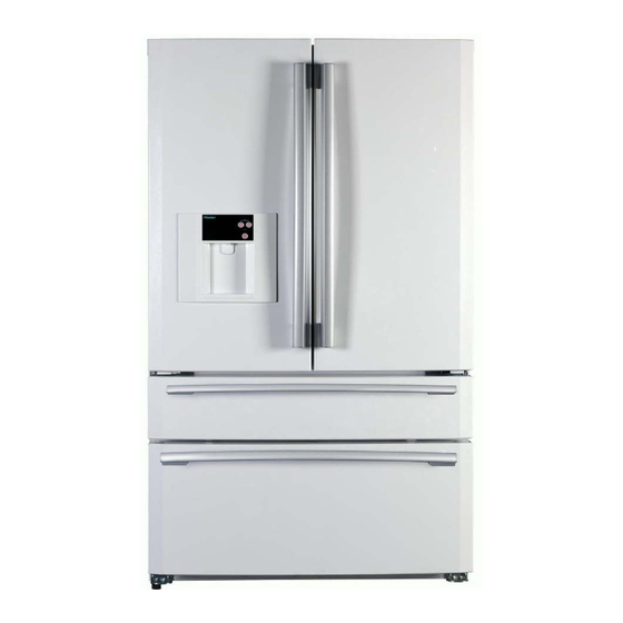
SERVICE MANUAL
MODEL:PBFS21EDAP/S/E
WARNING
◎2009(HAIER ELECTRICAL APPLIANCES COR. LTD)
All right reserved. Unauthorized copying and distribution is a violation of law.
Haier Group
Order No. Ref0910S006V0
Refrigerator
RBFS21TIAP/S/E
RBFS21SIAP/S/E
PRFS25EDAP/S/E
Advertisement
Table of Contents

Related Manuals for Haier PBFS21EDAP/S/E


Summary of Contents for Haier PBFS21EDAP/S/E
- Page 1 Product powered by electricity should by serviced or repaired only by experienced professional technicians. Any attempt to service or repair the product or products dealt with in this service information by anyone else could result in serious injury or death. ◎2009(HAIER ELECTRICAL APPLIANCES COR. LTD) All right reserved. Unauthorized copying and distribution is a violation of law.
-
Page 2: Table Of Contents
CONTENTS CONTENTS PAGE 1. PARTS IDENTIFICATIONS--------------------------------------------------------------1 2. PARTS DISASSEMBLY -------------------------------------------------------------- 2-8 2.1 Door Removal----------------------------------------------------------------------------2 2.2 Freezer Drawer Removal--------------------------------------------------------------3 2.3 Dispenser Panel Label Removal-----------------------------------------------------4 2.4 Mullion and Mullion Heater Replacement----------------------------------------5-7 2.5 Freeze Sensor Replacement----------------------------------------------------------8 3. CONTROL AND DISPLAY SYSTEM---------------------------------------------9~15 4. REFRIGERATION PRINCIPLE-------------------------------------------------------16 System flow chart and scenograph------------------------------------------------------16 5. - Page 3 PRODUCT CODE and SERIES INTRODUCTION Model Designations Bottom Mount 21 - 25 cu ft Refrigerator / Freezer Details: P B F S 21 E D A S S: Stainless E: Black P: White A: Production series D: Dispenser and Icemaker I: Icemaker E: Elite S: Supreme T: Plus 21:Capacity S: Spill-proof shelving...
-
Page 4: Parts Identifications
PARTS IDENTIFICATIONS Freezer Diary foChill-cold storage Liquid rack Slide rack Fruits and Gallon bottled seat Cooked- Ice-making drawer Deepfreeze refrigeration big drawer Deepfreeze Ice-maker fridge Ice spoon Ice-meeting drawer Drawer clapboard Deepfreeze fridge big drawer For the application of this brochure to different models, the characteristics of the refrigerator you are using may be different from the descriptions in this brochure. -
Page 5: Parts Disassembly
DISASSEMBLY 2.1 Right French Door Removal and Installation 1. Remove the screws on the top hinge cover,then set aside the top hinge cover and lay it down for installing later; 2. Using a screwdriver,remove the top hinge screws.Remove the hinge,then take the door off and place it aside;... -
Page 6: Freezer Drawer Removal
DISASSEMBLY 2.2 Center Freezer Drawer Removal and Installation 1. Firstly,open the door as far as possible,and take off the drawer, then remove the screws fixing slideway on each side of the drawer; 2. Pull the drawer body up and towards you,then place it aside; 3. -
Page 7: Dispenser Panel Label Removal
DISASSEMBLY 2.3 Instruction of removal Dispenser Panel Label on BM21 series (Only for those models with Water Dispenser) Tools Required: Knife or sharp screwdriver Warning: Please do protect the refrigerator! Instruction: 1. Insert the knife under the panel label to remove the label. 2. -
Page 8: Mullion And Mullion Heater Replacement
DISASSEMBLY 2.4 Instruction of Assembling Door Mullion on BM21/25 series 1. Install top axis of mullion through the heater; 2. Paste the heater onto mullion; 3. Fix the earth wire; 4. Install the reinforce metal and foam on the bottom cover; 5. - Page 9 DISASSEMBLY Instruction of Replacing Door Mullion heater on BM21/25 series 1. Remove the screws on mullion; 2. Disconnect the earth wire and connector; 3. Remove the screws on mullion; 4. Remove the upper cover,seal and bottom cover; 5. Remove the screw fixing earth wire; 6.
- Page 10 DISASSEMBLY Instruction of Replacing Horizontal Mullion heater 1. Remove the screws fixing horizontal mullion; 2. Dismantle the horizontal mullion and foam airproof; 3. Disconnect the linking clip and mullion heater; 4. Remove the screw fixing earth wire of heater,then tear off the heater; 5.
-
Page 11: Freeze Sensor Replacement
DISASSEMBLY 2.5 Instruction of removal FRZ sensor on BM21/25 series 1.Remove the FRZ airpassage cover; 2.Remove the rear gasket of FRZ airpassage cover,then you can see the FRZ sensor; 3.Take off the sensor from the clip; 4.FRZ sensor wire 5. Install the FRZ sensor according to the above steps. -
Page 12: Control And Display System
CONTROL and DISPLAY SYSTEM The dispenser display panel (Only for PBFS21****/PRFS25E*** series) A-------Hour Button B-------Minute Button C-------Lock Button D-------Time Area WARNING: There is a hidden screw under the dispenser display panel. The cabinet display panel Control Panel for PBFS21****/RBFS21T***/PRFS25E*** models Control Panel for RBFS21S*** models E------Express Freeze Button F.G--------Freezer Temperature Adjusting Button... - Page 13 CONTROL and DISPLAY SYSTEM 3.1 Lock and Unlock (Only for PBFS21****/PRFS25E*** series) Press Button C: After the first chime, the light indicator lock is in effect, the clock settings are fixed, and the function of getting cold drinks is locked; Press Button C again: After the first chime, the light goes out, indicating the clock settings can be adjusted.
- Page 14 CONTROL and DISPLAY SYSTEM 3.3 Freezer temperature adjustment Control Panel for PBFS21****/RBFS21T***/PRFS25E*** models Control Panel for RBFS21S*** models Press Button F or G: the freezer temperature indicating area will flicker. When the temperature is set, the temperature range is -6 to 6 degree F. Each time you press Button G, temperature will increase a level, until the highest level is reached;...
- Page 15 CONTROL and DISPLAY SYSTEM 3.5 Express Freeze setting Control Panel for PBFS21****/RBFS21T***/PRFS25E*** models Control Panel for RBFS21S*** models The function of Express-freeze is to freeze the food completely in the shortest time. Press Button E: The Express-freeze button indicator will light, and the freezer will be in Express-freeze mode.
- Page 16 CONTROL and DISPLAY SYSTEM 3.7 Centigrade / Fahrenheit display conversion function Control Panel for PBFS21****/RBFS21T***/PRFS25E*** models Control Panel for RBFS21S*** models Press Button F, G, and J for 3 seconds: After the first chime, Centigrade Temperature readings will be in effect. Press them for 3 seconds again, it will change to Fahrenheit Temperature readings.
- Page 17 CONTROL and DISPLAY SYSTEM 3.10 DEMO mode Control Panel for PBFS21****/RBFS21T***/PRFS25E*** models Control Panel for RBFS21S*** models Press Button F, G and K for 3 seconds: The function of DEMO will be available. There will be "_ _" on REF and FRZ temperature indicating area (H and I) just as below: In the DEMO mode, when the REF door is opened, the REF lamp will be on and then closed after 7 minutes, but the fan will be closed after 2 minutes when the REF door is opened.
- Page 18 CONTROL and DISPLAY SYSTEM 3.12 Door ajar alarm The function will be started when any door is opened for over 60 seconds. There will be chime on 30 seconds intervals until all the doors are closed. 3.13 Display Panel Power Down The cabinet display panel: 30 seconds after adjusting any button, the digital screen will go out automatically.
-
Page 19: Refrigeration Principle
REFRIGERATION PRINCIPLE SYSTEM FLOW CHART 1.Compressor 2.Condenser 3.Dew Proof pipe 4.Dry filter 5.Capillary tube 6.Evaporator 7.Suction tube SYSTEM FLOW SCENOGRAPH... -
Page 20: Circuit Diagram
CIRCUIT DIAGRAM 5.1 Schematic... -
Page 21: Circuit Diagram
CIRCUIT DIAGRAM... - Page 22 CIRCUIT DIAGRAM...
-
Page 26: Sensor And Error Code
SENSOR AND ERROR CODE Error Code Sensor Location REF sensor Right side wall of Fresh food compartment FRZ sensor Back side wall of Freezer compartment Ambient sensor(rounded) Under upper hinge(left) cover Defrost sensor Top right corner evaporator Icemaker sensor Icemaker flex tray Humidity sensor(cubic) Under upper hinge(left) cover REF sensor/Ambient... -
Page 27: Common Troubles In Refrigerators And Remedies
TROUBLESHOOTING 7.1 Analysis of Troubles and Troubleshooting A. Poor Refrigerating Effect The so-called “poor refrigerating effect “ refers to the fact that the refrigerator can operate and refrigerator normally, but the temperature in the refrigerator cannot drop to the prescribed value under the stipulated working conditions. - Page 28 Remedy According to the operating procedures, it is mandatory to turn the machine off, and several minutes later, open the refrigerant charging tube and let the refrigerant escape from it, replace the dry filter, recharge refrigerant after evacuating, and then seal the charging port. 3) There is air left in the refrigerating system Analysis of Trouble Residual air in the refrigerating system will reduce its refrigerating efficiency .The prominent...
- Page 29 confused. Generally speaking, you can make a judgment based on the frost formed on the evaporator. If the frost does not cover the evaporator, and moreover, it is loosely formed, you can make a judgment that the deterioration of refrigerating effect is due to the accumulation of refrigerating oil left in the evaporator tubing in case no other troubles have been found.
- Page 30 Remedy Check the whole machine, particularly those locations, which are liable to leak. After leak points have been found, repair them or replace them with new parts according to specific circumstances, then evacuate the system and finally charge refrigerant. 2) Refrigerating system has been clogged a) Clogged with Ice Analysis of Trouble The dryness treatment for the major parts in the refrigerating system has been performed...
- Page 31 Remedy Dismantle the system, remove the dry filter from it, purge the tubing with nitrogen, install a new filter, then evacuate it and finally charge it with refrigerant. C) Clogging in filter Analysis of Trouble Total clogging of a filter is rarely to occur. The paste-like matter formed from the substances filled into the system mostly causes this trouble or other dust after the refrigerator has been used for a longer time, or by the dirt accumulated gradually inside the filter.
- Page 32 A)Too much refrigerant charged into the system Analysis of Trouble The phenomenon, such as loose frosting and poor refrigerating effect, may occur if excessive refrigerant has been charged into the system. Superfluous refrigerant will occupy a certain space of the evaporator, thus reduce its heat dissipating area, and the phenomenon of “liquid striking”...
- Page 33 b) Overload of electric motor Analysis of Trouble Probably, too many things have been put into the refrigerator, and hence the thermal load exceeds its refrigerating capacity; or in case the power supply voltage drops considerably, the current flowing through the motor will increase drastically making the thermal protector actuate and the fuse blown, and hence the motor stops running.
- Page 34 b) Check the compressor accessories, including its thermal protector and relay. In case the thermal protector is damaged, the compressor cannot be powered on. If the relay is out of order, the motor will not run and hum sound can be heard from it after the compressor is turned on, in that case, shut it down immediately, otherwise, the motor windings will be burned out in case this condition lasts longer.
- Page 35 certain phase is low, this means that short circuit does exist in the windings and/or between turns, and insulation layers have been burned or deteriorated. A megametre can be used in this inspection, too. If the insulation resistance is lower than 2 M , this means that the insulation layer is already breakdown.
- Page 36 E. Compressor won't stop Sometimes, the compressor will run continuously (for several hours or run without end), If the food placed in the refrigerator is not too much, there may be the following two situations: I) the refrigerator very low, this means that the control system is probably out of order; ii) the control system works normally, and there are troubles in the refrigerating system or other parts.
- Page 37 Analysis of Trouble When the heat-insulation layer inside the case body deteriorates or the door seal is not closely touches the doorframe, the temperature in the refrigerator will rise and makes the compressor running continuously. Remedy Check the heat-insulation layer for its damaged parts; repair it to improve its heat-insulation property.
- Page 38 power supply circuit have been inversely connected accordingly ,this makes the null line become a live wire . G. Stronger vibration and loader noise 1) Refrigerator placed improperly a) Uneven ground Uneven ground will cause the refrigerator to be placed unsteadily, causing stronger vibration and noise during its operation.
-
Page 39: Troubleshooting
TROUBLESHOOTING 7.2 REFRIGERATOR / WINE CHILLER SENSOR REPLACEMENT REFRIGERATOR / WINE CHILLER TEMPERATURE SENSOR REPLACEMENT Tools Required: Wire Cutters, Slip joint pliers. Issue: Some sensors are foamed into the cabinet liner and appear to be non repairable. This process allows the easy and approved replacement of the sensors. Caution: Follow instructions completely for a proper repair. -
Page 40: Instruction Of Check Variable Speed Compressor
TROUBLESHOOTING 7.3 Instruction of Check Variable Speed Compressor... -
Page 41: Other(Icemaker And Defrost Details)
OTHER 8. Icemaker and defrost details 1.You can manually start a defrost cycle according to Pressing and holding FRZ< , FRZ> temp adjust keys and RESET(or TEST) for 3 seconds and 2 times.There will be "T2,T2" on cabinet display panel(press the 3 keys one time,there will display “T1,T1”).
Need help?
Do you have a question about the PBFS21EDAP/S/E and is the answer not in the manual?
Questions and answers