
Subscribe to Our Youtube Channel
Related Manuals for Memjet MACH X


Summary of Contents for Memjet MACH X
- Page 1 MACH X DIGITAL COLOR LABEL PRINTER OPERATOR’s GUIDE Rev 4-14-15 Valid with R13.11 driver and 2015xxxx Firmware...
-
Page 2: Safety Precautions
SAFETY PRECAUTIONS THIS EQUIPMENT PRESENTS NO PROBLEM WHEN USED PROPERLY. HOWEVER, CERTAIN SAFETY RULES SHOULD BE OBSERVED WHEN OPERATING THE MACH X LABEL PRINTER. BEFORE USING THE PRINTER, YOU SHOULD READ THIS MANUAL CAREFULLY AND FOLLOW THE RECOMMENDED PROCEDURES, SAFETY WARNINGS, AND INSTRUCTIONS: ... -
Page 3: Table Of Contents
TABLE OF CONTENTS Table of Contents SECTION 1 – GETTING ACQUAINTED ...................... 1 ..............................1 RONT ..............................2 ............................3 RINT NGINE ............................... 4 ..............................5 NWINDER ................................ 6 INDER ..........................7 EFAULT RINTING ODES “R ” M : ................8 ONTROL ANEL UTTON... - Page 4 Roll to Cut Setup ........................... 43 Fanfold Setup ............................43 Planning to do “Full Bleed” (borderless) printing ................. 44 SECTION 3 – OPERATING THE PRINTER ....................45 ........................... 45 RINTER RIVER ROPERTIES General Tab ............................45 Layout Tab ............................48 Image Printing Adjustment Tips ......................
- Page 5 TABLE OF CONTENTS Capping Station Lip ..........................84 Paperpath Surfaces ..........................84 Printing Platen Surface ......................... 84 Ink Revolver Couplings .......................... 84 Cutter Assembly ............................ 84 PRINTER MAINTENANCE SCHEDULE ......................87 ........................ 88 REPARING RINTER FOR RANSPORT Local relocation ............................ 88 Remote relocation or shipping ......................
- Page 6 NOTES ______________________________________________________ ______________________________________________________ ______________________________________________________ ______________________________________________________ ______________________________________________________ ______________________________________________________ ______________________________________________________ ______________________________________________________ ______________________________________________________ ______________________________________________________ ______________________________________________________ ______________________________________________________ ______________________________________________________ ______________________________________________________...
-
Page 7: Section 1 - Getting Acquainted
SECTION 1 GETTING ACQUAINTED SECTION 1 – Getting Acquainted Front View Top Cover – Provides access to the Print Engine. Ink Tank Door – Provides access to the Ink Tanks and Service Station. Winder Interface Port – Winder Interconnect Cord plugs in here. Service Port –... -
Page 8: Rear View
SECTION 1 GETTING ACQUAINTED Rear View ON/OFF LED Button – Press to power-up or power-down the print engine. Note: The Main Power Switch must be ON, to power-up the print engine. POWERING-UP: About six seconds after pressing this button, it will begin to blink slowly. Then all lights will start to blink simultaneously. -
Page 9: Print Engine View
Latch extends and retracts the couplings from the Printhead. ® Printhead Cartridge – Memjet Printhead produces an 8.5" wide full color print area. Clamshell Latches – Lift both latches at the same time to open the top half of the Print Engine. –... -
Page 10: Ink Tank View
SECTION 1 GETTING ACQUAINTED Ink Tank View Cutting Blade Assembly – Used to cut the media web. Ink Tank Latches – Used to hold the Ink Tanks in the slots. NOTE: Please be sure that both sides, at the bottom part of the latch, are engaged. Ink Tank Dock –... -
Page 11: Unwinder
Unwinder; as tension is maintained or released by media web. 24V, 2.5A External Power Connector* – Only needed when using Unwinder with some other non-interfaced device. External Power is not needed when Unwinder is used with Mach X. NOTE: External power supply must be a UL Listed power supply. -
Page 12: Winder
Narrow media requires lower tension (0). Wide media requires higher tension (4). 24V, 2.5A External Power Connector* – For connecting printers or equipment other than the Mach X. NOTE: External power supply must be a UL Listed power supply. *Requires disconnecting wire from Winder circuit board and connecting wire from External Power Connector. -
Page 13: Default Printing Modes
SECTION 1 GETTING ACQUAINTED Default Printing Modes The Printer has three default Printing Modes “Roll to Roll”, “Roll to Cut”, and “Fanfold”. The PRINTING MODE is determined by the current condition/connection of the Unwinder and Winder. The Winder condition/connection also determines if the automatic function of the Cutter will be disabled or enabled. -
Page 14: Control Panel Button Function In "Roll To Roll" Mode
SECTION 1 GETTING ACQUAINTED Control Panel Button Function in “Roll to Roll” Mode: The Control Panel has 3 buttons with LED indicators. ON/OFF – Powers Print Engine Up or Down. WARNING! Power-down the printer, using the ON/OFF button before powering off the Main Power Switch. -
Page 15: Control Panel Button Function In "Roll To Cut" Or "Fanfold" Mode
SECTION 1 GETTING ACQUAINTED Control Panel Button Function in “Roll to Cut” or “Fanfold” Mode: The Control Panel has 3 buttons with LED indicators. ON/OFF – Powers Print Engine Up or Down. WARNING! Power-down the printer, using the ON/OFF button, before powering off the Main Power Switch. -
Page 16: Control Panel Led Indicators
SECTION 1 GETTING ACQUAINTED Control Panel LED Indicators CONTROL PANEL INDICATORS LED Sequence Printer Status Possible Options Control Panel Options ⃝ - Power Up Power cord plugged in, Power Switch ⃝ - Inactive ON/OFF ⃝ - Inactive Normal operation: ⃝ - Inactive Powering up. - Page 17 SECTION 1 GETTING ACQUAINTED CONTROL PANEL INDICATORS (continued) LED Sequence Printer Status Possible Options Control Panel Options ⃝ - Inactive Busy Signal: Wait for process Maintenance running ⃝ - Inactive to finish. Job loading ⃝ - Inactive Wait for process to ⃝...
-
Page 18: Section 2 - Installing The Printer
SECTION 2 INSTALLING THE PRINTER SECTION 2 – Installing the Printer Before using the Printer the following must be done: • Choose a location for the Printer (plus the Unwinder and Winder if used) • Unpack the Printer (plus the Unwinder and Winder if used) •... -
Page 19: Choosing The Location
SECTION 2 INSTALLING THE PRINTER Choosing the Location The Printer should be placed on a sturdy level worktable or cabinet at least 9 inches from any walls. The surface should be large enough to accommodate the Printer, and Unwinder and Winder if used, in a line together. -
Page 20: Unpacking
SECTION 2 INSTALLING THE PRINTER Unpacking Printer: Remove the Printer from the packaging as shown below. Two people will be required to safely lift the printer and place it onto a sturdy, level work table. IMPORTANT: WORK TABLE SURFACE MUST BE LEVEL! Save all packaging materials. -
Page 21: Contents Of Printer Packaging
SECTION 2 INSTALLING THE PRINTER Contents of Printer Packaging The following items are included with your printer: Mach X Printer Ink Tanks – Cyan, Magenta, Yellow, Black, Black Printhead AC Power Cord USB Cable CD containing Operations Manual and Printer Drivers... -
Page 22: Removing The Cardboard Shipping Insert
SECTION 2 INSTALLING THE PRINTER Removing the cardboard Shipping Insert WARNING! To avoid possible damage to the printer; do NOT plug-in, or power-up, the printer until all shipping materials have been removed; as described below. 1. Open the Top Cover. 2. -
Page 23: Install Printer/Winder Spacer Plate
SECTION 2 INSTALLING THE PRINTER Install Printer/Winder Spacer Plate: WARNING: Do NOT tilt the printer or place it on its side to install/remove rubber feet and spacer plate/spacers. Intead, move printer to edge of bench or table to remove feet and install spacer plate/spacers. 1. -
Page 24: Connecting The Printer
SECTION 2 INSTALLING THE PRINTER Connecting the Printer Plugging in the Printer • Check to make sure the Main Power Switch [1] is in the OFF position. • Plug the Power Cord into the receptacle [1] at the rear of the Printer. •... -
Page 25: Connecting To The Computer
SECTION 2 INSTALLING THE PRINTER Connecting to the Computer The Printer connects to the computer through the USB port [3]. A Network port [2] is provided when operating in a network environment. The Unwinder Interface Port [4] is located just below the USB port. IMPORTANT: Do NOT connect the printer to the computer, until prompted to do so, during the printer driver installation process. -
Page 26: Installing The Printer Software (Driver & Toolbox)
Uninstall the old software before installing the new software. Use the “Uninstall” feature found on your computer system under All Programs, “Memjet”, “MC Series Driver”. IMPORTANT: Before installing the Printer software (Toolbox and Driver), you should temporarily disable all antivirus programs and firewalls. - Page 27 SECTION 2 INSTALLING THE PRINTER 4. The “License Agreement” window opens. Carefully read the “Software License Agreement”. If you agree to the terms, check “I accept…” then click Next>. 5. After a few moments the “Printer Connections” window opens. Click “Configure to print using USB”.
- Page 28 SECTION 2 INSTALLING THE PRINTER 8. The “Finished software installation” window opens. Do not check the Print Test Page as the Printer is not set up yet. You can also set the printer to be the default printer. To complete the process you must reboot the computer.
-
Page 29: Connecting The Printer Via Network (Ethernet Port)
SECTION 2 INSTALLING THE PRINTER Connecting the Printer via Network (Ethernet Port) The following procedure is written for network systems that do not provide an automatic IP Address. In this case a static IP Address must be entered into the printer's "network status and configuration" window. Important: Initially, a USB connection to the printer is needed;... - Page 30 SECTION 2 INSTALLING THE PRINTER 5. Using a Cat5 network cable; connect the printer to your network via the Ethernet port. 6. Click on “Diagnostics”. The “Diagnostics” window will open; displaying a lot of information about the printer. This information will include the Network Status and configuration settings.
-
Page 31: Installing The Ink Tanks
SECTION 2 INSTALLING THE PRINTER Installing the Ink Tanks The Printer uses five Ink Tanks (two Black, one Cyan, one Magenta, and one Yellow). The Ink Tank is a delicate, precision device. Handle with extreme care to avoid damage. Ink Tank Anatomy The ink used in this system may be harmful if swallowed. - Page 32 2. Open the MC Series Toolbox. Go to the Start Menu, All Programs, select the “Memjet” folder, select the “MC Series Driver” folder and Open the “Toolbox”. Tip: If you receive warning that Windows Firewall has blocked some features of this program.
- Page 33 SECTION 2 INSTALLING THE PRINTER 6. Slide the new Ink Tanks (label up) into their appropriate color slots [B]. INSTALLATION TIP: Make sure the Ink Tanks seat properly. Insert the Tank into the appropriate Ink Station, then pull the Ink Tank back about an inch and push forward firmly to insure that the Ink Nozzles penetrate the seals on the Tanks.
-
Page 34: Install The Printhead Cartridge
SECTION 2 INSTALLING THE PRINTER Install the Printhead Cartridge The Digital Color Printer uses a single Memjet® printhead cartridge. The Printhead Cartridge is a delicate, precision device. Handle with extreme care to avoid damage and issues that could degrade print quality. - Page 35 SECTION 2 INSTALLING THE PRINTER CAUTION! • Use electrostatic discharge (ESD) handling precautions. • Hold the Printhead Cartridge by the handles ONLY. • DO NOT touch the ink couplings, nozzle surface or electrical contacts. • DO NOT unpack the Printhead Cartridge until the Printer is ready for installation.
- Page 36 SECTION 2 INSTALLING THE PRINTER Procedure (Installing the Printhead Cartridge): This procedure assumes that you are installing a Printhead Cartridge into a printer that does NOT have a Printhead Cartridge installed. If your printer already has a Printhead Cartridge installed, and you wish to replace the Printhead Cartridge;...
- Page 37 SECTION 2 INSTALLING THE PRINTER 5. Carefully remove the Printhead Cartridge from the foil vacuum packaging. Tear at notch or cut end with scissors. CAUTION: DO NOT touch the ink couplings, printhead nozzle surface or electrical contacts. [A] Remove the protective plastic cover. Hold the Printhead cartridge by the handle.
- Page 38 SECTION 2 INSTALLING THE PRINTER 6. Carefully insert the Cartridge into the compartment at an angle [4], with the Printhead surface facing down and the Ink Couplings facing the Ink Revolver Couplings (ink hoses). Once it is seated, gently tilt the Cartridge forward until it snaps into an upright position [5]. DO NOT FORCE the Cartridge into position.
- Page 39 SECTION 2 INSTALLING THE PRINTER 9. Immediately after wetting the nozzles. Carefully close and latch the Print Engine Clamshell. CAUTION HOLD ONTO BOTH LATCHES WHEN OPENING AND CLOSING THE PRINT ENGINE CLAMSHELL TO PREVENT DAMAGE. DO NOT FORCE THE CLAMSHELL CLOSED. DO NOT OPEN THE CLAMSHELL DURING THE PRIMING PROCESS.
- Page 40 SECTION 2 INSTALLING THE PRINTER 12. Watch the Toolbox screen on your computer. Notice that some of the information is in red. As the printer circulates ink and primes the system these fields should all turn black. This may take a few minutes.
-
Page 41: Removing/Cleaning/Installing The Head Media Guide
If needed; you can remove the Head Media Guide to clean behind this area. Note: The Head Media Guide may be made of two different materials (metal or plastic). The white plastic version is now common for the Mach X Label Printer. 1. Open the Top Cover 2. -
Page 42: Attaching/Aligning The Unwinder And Winder
SECTION 2 INSTALLING THE PRINTER Attaching/Aligning the Unwinder and Winder Unwinder The Unwinder is used for “Roll to Cut” and “Roll to Roll” applications. Proper alignment of the Unwinder and Printer is critical to operation of the Printer. Position the Printer on a sturdy, stable level work surface with enough room to place the Unwinder at the entry end of the Printer. -
Page 43: Winder
SECTION 2 INSTALLING THE PRINTER Winder The Winder is used, in conjunction with the Unwinder, for “Roll to Roll” applications. Proper alignment of the Unwinder, Printer and Winder is critical to operation of the Printer. Position the Printer on a sturdy, stable level work surface with enough room to place the Unwinder and Winder at the entry and exit ends of the printer. -
Page 44: Connecting The Unwinder And Winder To The Printer
SECTION 2 INSTALLING THE PRINTER Connecting the Unwinder and Winder to the Printer WARNING! HAZARDOUS MOVING PARTS! KEEP FINGERS AND OTHER BODY PARTS AWAY! CAUTION MAKE SURE THAT THE PRINTER IS TURNED OFF BEFORE CONNECTING/DISCONNECTING THE UNWINDER AND WINDER. Connecting the Unwinder to the Printer: 1. -
Page 45: Unwinder/Winder Controls & Function
Mode Switch The Unwinder has a Mode Switch for “Auto” or “Manual” operation. . Auto – Use this setting when the Unwinder is interfaced to the Mach X. Unwinder is controlled (disabled/enabled) by the Printer thru the interface cable. This control allows easy roll loading since the Unwinder will not start turning when the Label Tension Arm is lifted to load labels/media. -
Page 46: Winder
In general, the Winder speed can be set to maximum (fully clockwise); when it is being used with the Mach X. The Winder speed control adjustment is more important when the Winder is used with a device other than the Mach X (non- interfaced device). -
Page 47: Loading Labels/Media
SECTION 2 INSTALLING THE PRINTER Loading Labels/Media Roll to Roll Setup IMPORTANT! Make sure the Unwinder and Winder are connected to the Printer and the Winder is powered ON. This will ensure that the automatic cut function of the Cutter is disabled. (Cutter can still be engaged manually by pressing the CUT/EJECT (Cancel) Button. - Page 48 SECTION 2 INSTALLING THE PRINTER [D] Feed the media under the Brush Assembly and into the printer. Be sure to align the non- operator side of the media leader with the two alignment pins [D] on the Printer Then gently push the media into the Printer until it hits resistance (leader touching Print Engine feed roller).
-
Page 49: Roll To Cut Setup
SECTION 2 INSTALLING THE PRINTER 8. Load an empty 3" core onto the Winder Spindle. 9. Slide the Spindle Lock/Guide [A] onto the shaft until the 4 pins fit into the roll core. Tip: Do not push the Spindle Lock/Guide up against the side of the media. -
Page 50: Planning To Do "Full Bleed" (Borderless) Printing
SECTION 2 INSTALLING THE PRINTER 2. Place Fanfold Labels [A], label-side up, next to the feed end of the Printer. 3. Feed the Labels under the Brush Assembly [B] and into the printer. Be sure to align the non-operator side of the media leader with the two alignment pins [C] on the Printer Then gently push the media into the Printer until it hits resistance (leader touching Print Engine... -
Page 51: Section 3 - Operating The Printer
SECTION 3 OPERATING THE PRINTER SECTION 3 – Operating the Printer Once the Printer Driver is installed on your computer and the Printhead is primed, you are ready to start printing. Set up your job and send it to the Printer. The Printer will start and print. The Printer Driver should be set as the default driver. - Page 52 SECTION 3 OPERATING THE PRINTER • Copies – Lets you choose the number of copies to be printed. NOTE: Driver has a limit of 32,767 copies. However, in some cases, copies are limited by the software program. For example; Adobe Acrobat® limits copies to 999. Reverse Order –...
- Page 53 SECTION 3 OPERATING THE PRINTER Full Bleed Tips: Labels with a 5 mm gap between them are required to do “full-bleed”; without machine skipping labels or resetting position of each label (media feeding back and forth). To avoid image expansion/distortion, please be sure to set/check the following: - Layout Tab.
-
Page 54: Layout Tab
SECTION 3 OPERATING THE PRINTER Layout Tab Layout allows you change how the document prints without changing the original document. • Resizing – Lets you specify the Original Size or Custom Resize: lets you resize the original as a % of normal size. - Page 55 SECTION 3 OPERATING THE PRINTER Bottom Adjustment – ((Bottom of Form (BOF)). Lets you extend or reduce the ability to print into the gap between media/labels; to account for the extra length needed to print past edge of label (full bleed printing). Range: -53.8mm up, to +200mm down.
-
Page 56: Image Printing Adjustment Tips
SECTION 3 OPERATING THE PRINTER Image Printing Adjustment Tips Tip: Adjustments are in relationship to the orientation of the print engine, not the image orientation. Top Adjust Left Adjust Label Feed Direction Bottom Adjustment (BOF) Max Page Width Label Feed Direction... -
Page 57: Import/Export Tab
SECTION 3 OPERATING THE PRINTER Import/Export Tab Import/Export is used to preserve any custom Watermarks, Media Sizes or Print Settings you may have developed for various jobs before unistalling/updating the Printer Driver. • Export – Use to send the custom settings to an “export file”... -
Page 58: Services Tab
SECTION 3 OPERATING THE PRINTER Services Tab Services allows you to: • Print Configuration Page – Prints out the current configuration of the Printer including current Firmware Version, Network Connection, Printer Serial Number and more. • Print Colorbar Page – Prints type and color bands to check print quality. -
Page 59: Using The Toolbox Utility
SECTION 3 OPERATING THE PRINTER Using the Toolbox Utility Once the Printer Driver is installed you have access to the Toolbox Utility. The Toolbox lets you monitor ink usage, perform diagnostic checks, print reports and run maintenance tasks on the Printer from your computer. -
Page 60: Menu Options
SECTION 3 OPERATING THE PRINTER Menu Options User Interface Menu [A] Screen Buttons: Let you perform maintenance and operating tasks. PRINT buttons: Pause/Resume, Cancel a Job, Clear Errors, Reset the Job Counter, and Reset the Page Counter. MEDIA buttons: Forward Media – Moves media forward into the printer when loading media. - Page 61 SECTION 3 OPERATING THE PRINTER [B] Basic Printer Settings – Lets you adjust automated service and cleaning intervals, adjust the feeder speed for a job and adjust the Printer for pre-printed media. Media Feed – Set for the type of “next page” detection you want the printer to use.
- Page 62 SECTION 3 OPERATING THE PRINTER Mid Job Servicing – Sets the frequency of automatic maintenance that will be done during a Roll to Cut job. Settings are: Default (14m), Level 4 (100m), Level 3 (250m), Level 2 (375m), Level 1 (500m) and Off ∞) .
- Page 63 SECTION 3 OPERATING THE PRINTER Release the Printhead – Pumps ink back into the Ink Tanks and opens the Printhead Latch to remove or install the Printhead Cartridge. Shutdown – Turns the Printer OFF. For best system performance, it is recommended to keep the Print Engine powered-up (ON/OFF light illuminated) at all times.
-
Page 64: Diagnostics Menu
(2” horizontal x 1” vertical block). The more frequent a particular nozzle is fired, the quicker it will begin to fail. Memjet’s estimated printhead rating: ~125,000* linear inches of continuous printing. *This is NOT an expression of Warranty. Individual results will vary. - Page 65 SECTION 3 OPERATING THE PRINTER Ink Estimation Mode This feature lets you predetermine approximately how much ink a given job may use prior to printing a job. This can be useful for determining approximate per piece costs without wasting any materials/supplies.
-
Page 66: Network Configuration Menu
SECTION 3 OPERATING THE PRINTER Network Configuration Menu Permits you to view, enter or change settings to connect the Printer to your network. See “Connecting the printer via Network (Ethernet Port)” for more details. Network Connection Set Up: 1. The Printer is still connected to the computer via the USB cable. To connect the Printer to a network, open the Toolbox. -
Page 67: Service Menus
SECTION 3 OPERATING THE PRINTER Service Menus For authorized personnel only. Provides access to more advanced Printer control and maintenance menus. Stop Refresh/Auto Refresh Use this button to stop and start the auto refresh feature of the Toolbox (web page). Stopping refresh may be helpful when trying to capture a screen shot of the Toolbox. -
Page 68: Section 4 - Operator Maintenance
SECTION 4 OPERATOR MAINTENANCE SECTION 4 – Operator Maintenance This section covers how to care for the Printer, Ink Tanks, Printhead Cartridge, Service Station, etc… Ink Tanks Replacing the Ink Tanks Replace the Ink Tanks when the ink runs out. This procedure is almost identical to the procedure for installing new Ink Tanks into a new printer. - Page 69 SECTION 4 OPERATOR MAINTENANCE 5. Lightly clean the QA Chip contacts [C] with a pencil eraser. 6. Clean the Ink Level Prism [D] and QA Chip contacts [C] with a clean, dry, lint-free cloth. NOTE: You can dampen the cloth with distilled water to wipe the Prism, but DO NOT get the QA Chip contacts wet.
-
Page 70: Ink Tank Storage
SECTION 4 OPERATOR MAINTENANCE Ink Tank Storage • Properly stored unopened Ink Tanks have a shelf life of up to 1 year. • Opened Ink Tanks should remain in the printer. • New Ink Tanks should be stored in their original packaging. •... -
Page 71: Printhead
SECTION 4 OPERATOR MAINTENANCE Printhead Cleaning the Printhead Cartridge The Printhead Cartridge is cleaned automatically; each time the print engine is powered ON/OFF, at the beginning and end of a print job, periodically during the print job, whenever there is an interruption in printing and when a “Clean Printhead”... -
Page 72: Manual Printhead Cleaning
SECTION 4 OPERATOR MAINTENANCE Manual Printhead Cleaning: NOTE: We recommend the use of powder-free, nitrile gloves for this process. As a last resort, if running the built-in “Clean Printhead” Levels doesn’t help improve print quality; the printhead cartridge can be cleaned manually. 1. -
Page 73: Removing/Replacing The Printhead Cartridge
SECTION 4 OPERATOR MAINTENANCE Removing/Replacing the Printhead Cartridge NOTE: We recommend the use of powder-free, nitrile gloves for this process. Replacing the Printhead Cartridge 1. Open the Toolbox Utility. Go to the Start Menu, then open the Toolbox. 2. Open the Top Cover. 3. -
Page 74: Printhead Storage & Shelf Life
SECTION 4 OPERATOR MAINTENANCE Printhead Storage & Shelf Life Properly stored, unopened, Printhead Cartridges have a shelf life of up to 1 year. ° Long Term: 14° F to 86° F (-10 C to 30° C Short Term: -11° F to 140° F (-25° C to 60° C) Storage Temperature Range: NOTE: Cumulative storage duration above 86°... -
Page 75: Inspecting & Cleaning The Lip Of The Capping Station
SECTION 4 OPERATOR MAINTENANCE Inspecting & Cleaning the Lip of the Capping Station The Capping Station (Cap) is part of the Service Station. When the printer is idle, the Service Station automatically caps the printhead to keep the nozzles hydrated. Excess ink can accumulate on the Lip of the Cap. -
Page 76: Inspecting The Wiper Roller
SECTION 4 OPERATOR MAINTENANCE Inspecting the Wiper Roller The Wiper Roller should be routinely inspected for signs of wear and debris. NOTICE! If you have not been trained or are uncomfortable performing this task, please contact your service support representative. Directions: 1. -
Page 77: Cleaning/Replacing Service Station Items
SECTION 4 OPERATOR MAINTENANCE Cleaning/Replacing Service Station Items The Service Station contains separate areas/devices that are used to perform the following tasks. • Cleaning. The Wiper Roller cleans the Printhead nozzles of excess ink and debris. • Printing/Purging. The Printing Platen acts as a base to support media during printing. It also contains a purging area;... - Page 78 SECTION 4 OPERATOR MAINTENANCE 4. Open the Clamshell. Release the two latches and open the Clamshell. WARNING! Please be sure to open the Clamshell before you eject the service station. If not, the service station cannot fully eject and damage to the service station drive system may occur.
- Page 79 SECTION 4 OPERATOR MAINTENANCE 5. Remove the Service Station completely from the print engine and place it on a non-absorbent surface (plastic bag) to protect the surface you are placing it on. 6. If you are replacing or re-installing the Service Station, please see the section titled “Installing the Service Station”.
-
Page 80: Cleaning The Service Station
SECTION 4 OPERATOR MAINTENANCE Cleaning the Service Station NOTE: We recommend the use of powder-free, nitrile gloves for this process. Caution: Please be sure that you are using proper cleaning techniques to clean items that come in contact with the printhead. Use only distilled or deionized water and lint free cloths. If you don’t follow this rule, you will introduce contamination into the printhead;... - Page 81 SECTION 4 OPERATOR MAINTENANCE Wiper Motor Assembly Removal and Cleaning Removal: 1. Disconnect (unplug) the wiper motor cable from the Service Station Printed Circuit Board [A]. 2. Remove the Printed Circuit Board [A] from the Service Station Tray. Carefully release clips to remove board.
- Page 82 SECTION 4 OPERATOR MAINTENANCE Printing Platen and Capping Station Removal and Cleaning Removal: Both of these items simply lift out for removal from the Service Station. Cleaning: 3. Rinse off ink using tap water. Tip: Make sure the valve, located on the bottom of the Capping Station, is clear of debris and working.
-
Page 83: Installing The Service Station
SECTION 4 OPERATOR MAINTENANCE Installing the Service Station CAUTION THIS PROCESS MUST BE PERFORMED BY A QUALIFIED/TRAINED PERSON. NOTICE: Due to the technical nature of this procedure; it should only be performed by a qualified technical support person or someone that has been properly trained on this procedure. Please contact your technical support representative. - Page 84 SECTION 4 OPERATOR MAINTENANCE 7. Slide the Cable Securing Latch open on the Service Station Circuit Board; as shown below. Closed Opened 8. Locate the Ribbon Cable (from within the Service Station Slot). Insert the Ribbon Cable (blue side up) into the space under the Cable Securing Latch [1].
- Page 85 SECTION 4 OPERATOR MAINTENANCE 10. Look down through open area, in the Print Engine, to make sure the Service Station is aligned with the “Bar”; (Service Station Drive Shaft) as shown. If the Printhead Cartridge is not installed (has been removed), you can look down through the top of the Print-Engine, through the Printhead Cartridge opening.
-
Page 86: Still Experiencing Print Quality Issues
SECTION 4 OPERATOR MAINTENANCE 12. Turn the printer’s Main Power Switch ON; then press the control panel’s ON/OFF button. After printer initialization (~45 seconds) the Print Engine will automatically pull the Service Station the rest of the way in. NOTICE: If the Service Station should get jammed during this process (you hear motor stall noise or gear slipping noise);... -
Page 87: Inspecting/Replacing The Waste Ink Tray
SECTION 4 OPERATOR MAINTENANCE Inspecting/Replacing the Waste Ink Tray The Waste Ink Tray (123-2487) is filled with an absorbent material, used to capture the waste ink that drains from the Service Station. 1. If the printer is on; press the ON/OFF button to power-down the print engine. Wait about 45 seconds until the system shuts down (all control panel lights will go off). -
Page 88: Clearing Media Jams
SECTION 4 OPERATOR MAINTENANCE Clearing Media Jams When the printer detects a media feed problem, it will stop automatically. Depending on where the media stops; the message “PAPERPATH_PAPERJAM” or “PAPERPATH_FEED_TIMEOUT” will be displayed in the Toolbox. Once the jam has been removed from the system and the Clamshell is closed; reload media into printer then press the PAUSE/RESUME button, on the control panel or the Toolbox, to continue printing. -
Page 89: Misfeeds
SECTION 4 OPERATOR MAINTENANCE Misfeeds When media tracking/positioning is affected; this is considered a Misfeed. If the media misfeeds, this will affect the clarity and location/registration of the image being printed on the media. Examples: Unwinder speed set too slow. Unwinder may hold-back on the media causing it to hesitate/slip. When this occurs the image will be distorted (condensed) and or print early (image moves towards or off leading edge of label). -
Page 90: Cleaning Other Items Inside The Print Engine
SECTION 4 OPERATOR MAINTENANCE Cleaning Other Items inside the Print Engine Areas in the Print Engine can become glazed with a buildup of dust, paper lint and accumulated ink and need to be cleaned regularly. This section covers the procedures for cleaning the following items. Grit Rollers (Media Transport Rollers) Media (Paperpath) Sensors Capping Station Lip... - Page 91 SECTION 4 OPERATOR MAINTENANCE 5. Use the procedures, as outlined below, to clean the following items. Grit Rollers [A]: Entry Mark Clean as needed using a small stiff-bristled brush (toothbrush), lightly moistened with distilled water. Do NOT use anything other than distilled water to clean the Rollers.
- Page 92 SECTION 4 OPERATOR MAINTENANCE Cleaning the Ink Revolver Couplings 1. First Deprime the system and remove the Printhead Cartridge. 2. Moisten a foam swab in distilled water. 3. Insert the swab into one of the ink channels and rotate the swab to clean the chamber. 4.
-
Page 93: Printer Maintenance Schedule
SECTION 4 OPERATOR MAINTENANCE PRINTER MAINTENANCE SCHEDULE General, periodic maintenance is needed to keep the Printer in good working order. Many tasks can be performed by operators with basic supplies, no special tools needed. Other tasks should only be performed by trained service personnel. -
Page 94: Preparing Printer For Transport
SECTION 4 OPERATOR MAINTENANCE Preparing Printer for Transport Please use this procedure if you ever need to transport the printer to a new location or ship the printer. Please refer to the appropriate sections in the manual for details on installing/removing items from the printer. - Page 95 SECTION 4 OPERATOR MAINTENANCE 9. Remove the Printhead Cartridge and install protective covers on printhead. Be careful to avoid ink spills (drips) and stains during this process. Store Printhead Cartridge in a sealed plastic bag with a damp cloth. CAUTION: Make sure the cartridges electrical contacts are dry before re-installing printhead. 10.
-
Page 96: Section 5 - Troubleshooting Guide
SECTION 5 TROUBLESHOOTING Section 5 – Troubleshooting Guide The following troubleshooting guides are provided to assist you in solving any problems that might occur with the Digital Color Printer. We have tried to make them as complete as possible. The best advice we can offer is to make sure that the system is set up properly, plugged in, and that it has an adequate supply of ink before attempting to troubleshoot any problem. -
Page 97: Examples Of Print Quality Issues (Including Possible Causes And Solutions)
Examples of Print Quality Issues (including possible causes and solutions) The Memjet printhead cartridge contains 70,400 inkjet nozzles. These nozzles are divided into ten rows; two rows of nozzles for each color channel. Due to the high number of nozzles; it is not uncommon for some nozzles to become contaminated, dehydrated or clogged. - Page 98 SECTION 5 TROUBLESHOOTING Clogged/Damaged/Dead Nozzles: Clogged/damaged/dead/ nozzles will normally show as thin, crisp, vertical lines of missing color. Multiple adjacent nozzles, with same issue, will show as wider, crisp, vertical lines of missing color. Clogged nozzles are normally due to Printhead nozzle dehydration or partial contamination. Damaged nozzles are normally due to improper cleaning or debris on wiper roller causing damage to head.
- Page 99 SECTION 5 TROUBLESHOOTING Color Mixing Issues: Color mixing will show as muddy, mottled or distorted (grainy) colors. Color mixing occurs when the ink from one color channel crosses over into another color channel. Since the inkjet nozzle rows are located very close to one another (ten rows of 7,040 nozzles, located within a 0.8 mm space), it is easy for partials or fibers to create bridges across color channels.
- Page 100 SECTION 5 TROUBLESHOOTING Scuff Marks and Smudging Issues: Scuff Marks occur when the media makes contact with an area of the printhead that has ink on it. Smudging occurs when the wet image, on the media, makes contact with something (most commonly the printhead) before it is dry.
- Page 101 SECTION 5 TROUBLESHOOTING Smudging: Here is an example of “smudging” that occurred when an area of this page, with a wet image, made contact with the printhead. Note: There are also scuff marks in this example. As mentioned previously; smudging will increase the chance for scuff marks;...
- Page 102 SECTION 5 TROUBLESHOOTING Fuzzy/Distorted Print Fuzzy/distorted print can occur for a number of reasons; listed/shown below. Problem: Poor original image quality (less than 300 dpi). Solution: Use high quality images. Problem: Choosing to print image in low resolution from software application. Solution: Set image to highest resolution possible from software application.
-
Page 103: The Ink Tank(S)
SECTION 5 TROUBLESHOOTING The Ink Tank(s) CONDITION PROBLEM SOLUTION Installed New Ink Tank and One or more of the “septum Try removing and re- shortly after the related Ink needles” didn’t fully puncture the installing the Tank. See septum seal on the new Ink Tank. “Installing The Ink Tanks”. -
Page 104: The Printhead Cartridge
TROUBLESHOOTING The Printhead Cartridge The Memjet printhead cartridge contains over 70,000 inkjet nozzles. These nozzles are divided into ten rows; two rows of nozzles for each color channel. Due to the very tiny size of each nozzle and the high number of nozzles;... - Page 105 SECTION 5 TROUBLESHOOTING The Printhead Cartridge (continued) CONDITION PROBLEM SOLUTION Printhead nozzles dry (air pulled Wet the Printhead nozzles System will not prime the through nozzles; not allowing using distilled water and a printhead after installing system to create vacuum) wet, lint-free cloth.
-
Page 106: The Printer
SECTION 5 TROUBLESHOOTING The Printer NOTICE: The printer will not print if any of the five ink tanks are empty or missing. Dots Printed on Media CONDITION PROBLEM SOLUTION Very small dots (gray These dots are Intrapage (on the page) nozzle spitting is overspray) are being printed formed by intrapage normal. -
Page 107: Service Station Problems
SECTION 5 TROUBLESHOOTING Service Station Problems WARNING! Many of the issues related to Service Station function will require a qualified Service Person, or properly trained person, to diagnose and fix these issues. If you haven’t been properly trained on or don’t feel comfortable performing these procedures;... -
Page 108: Interface Communication Problems
SECTION 5 TROUBLESHOOTING Interface Communication Problems CONDITION PROBLEM SOLUTION Wrong USB port selected in Verify appropriate USB port MC Series Driver does not respond to printer being “MC Series Driver”. selection in the driver Ports Tab. connected via USB. Note: During driver install USB port was automatically assigned. -
Page 109: Feeding Problems
SECTION 5 TROUBLESHOOTING Feeding Problems CONDITION PROBLEM SOLUTION Label Side Guide set too tight to Readjust Label Side Guide. Intermittent feeding (media slipping or media. hesitating) Dirty Transport Rollers inside Ink on rollers can be patted-off with a print engine. damp, cloth. -
Page 110: Errors And Warnings
SECTION 5 TROUBLESHOOTING Errors and Warnings Printer Alert Window Messages Messages sent from the driver and displayed on PC screen in a small popup window. MESSAGE SOLUTION Wait until the message disappears. The printer will start printing your job Cleaning in Progress once the cleaning process has completed. -
Page 111: Toolbox System Status Messages
SECTION 5 TROUBLESHOOTING Toolbox System Status Messages Displayed, in red, in the MC Series Toolbox utility. SYSTEM STATUS PROBLEM SOLUTION PAPERPATH_END_OF_ROLL Out of media. Add new roll of media to Unwinder. Unwind, Label Load media into printer and press Tension Arm has hit RESUME button to continue. - Page 112 SECTION 5 TROUBLESHOOTING Toolbox System Status Messages (continued) Displayed, in red, in the MC Series Toolbox utility. SYSTEM STATUS PROBLEM SOLUTION X_INK_LOW X = Color. Ink Tank replacement will be necessary One or more Ink Tanks soon. Reorder Ink Example: CYAN_ INK_LOW are low on ink.
- Page 113 SECTION 5 TROUBLESHOOTING Toolbox System Status Messages (continued) Displayed, in red, in the MC Series Toolbox utility. SYSTEM STATUS PROBLEM SOLUTION [Crit 63 03-phead offline Dirty Printhead contacts. Eject Printhead and inspect/clean cancelpage restart] contacts. Printhead or Pen Board Replace Printhead fault.
- Page 114 SECTION 5 TROUBLESHOOTING Toolbox System Status Messages (continued) Displayed, in red, in the MC Series Toolbox utility. SYSTEM STATUS PROBLEM SOLUTION PRINTHEAD_UNPRIMED Printhead priming If just powered on, or Tanks/Printhead process has failed. just installed, wait a few minutes; error may clear by itself.
-
Page 115: Appendix A - Borderless Printing: Overspray Vs. Oversize
APPENDICES Appendix A – Borderless Printing: Overspray vs. Oversize The MC-Series Print Driver (under Printing Preferences) offers two ways for printing off the edges of the label/media, sometimes called "borderless" or "full-bleed" printing. Each option adjusts the relationship between the image, the selected media size and the actual media on which is it printed, but in different ways. - Page 116 APPENDICES Prerequisites for Overspray Since the scaling can distort the image, do not use Overspray for targets that have barcodes or text because this setting could render them unreadable. If the image is a photograph or other graphical image, the scaling may not be noticeable or objectionable.
- Page 117 APPENDICES Page Setup for Oversize When using the Oversize option, Resizing (located in the Layout Tab of the Driver) needs to be set to "Original Size". Page Setup for Oversize Option Impact of Using Oversize Selecting Oversize extends the Custom Sizes dimensions beyond that of the actual media being printed on. Since this size extension is equal in both X- and Y- axes, there is no distortion of the image.
- Page 118 APPENDICES ADDITIONAL CONSIDERATIONS AND TIPS Some additional considerations apply to both Overspray and Oversize in certain circumstances. Minimum Label Gap and Maximum Label Backing Width for Borderless Printing (Full Bleed) For both Overspray and Oversize, additional consideration and testing are required when approaching the limitations for minimum label gap and maximum label backing width.
-
Page 119: Appendix B - Printer Specifications
MEDIA SENSING NOTE: It is also possible to print on continuous media that does not have a “label gap”, “notch” or “tick-mark”. Water-based ink. 5 individual 250 ml ink tanks (CMYKK) ® One Memjet Printhead PRINT CARTRIDGE INTERFACE USB and Ethernet... -
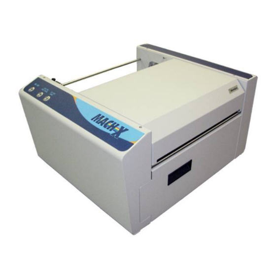
Page 120: Appendix C - Supplies And Accessories
Mach X Winder Obtaining Supplies, Service and Support Please contact your local Dealer/Distributor to obtain supplies, service and support for your printer. Service should only be performed by a qualified service representative. MACH X shown with optional Unwinder and Winder... - Page 121 INDEX Firmware Download ..........57 Function Accessories ............. 114 Unwinder ............39 Adjust Core Size ............41 Winder ..............40 Adjust Tension, Winder ..........40 Fuse ................1 Air in Nozzles ............91 Unwinder .............. 5 Alignment Notch, Unwinder ........5 Winder ..............
- Page 122 INDEX Service Life ............68 Storage ..............68 Main Power Switch ............. 1 Printhead Cartridge Protective Packaging ....28 Maintenance Printhead, Install............. 30 Wiper Roller Inspection ........70 Printing Media Guide Ring ............6 Default Printing Modes ........7 Menu Options, Toolbox ..........54 Minimum Requirements, System ......
- Page 123 INDEX Winder ..............40 Troubleshooting, Service Station Problems .... 101 Toolbox Utility Diagnostics ............58 Uninstall, Printer Driver..........20 Ink Estimation Mode .......... 59 Uninstall, Printer Software........20 Ink Usage ............58 Uninstall, Toolbox Utility ......... 20 Ink Usage Menu ..........58 Unpacking Printer .............
- Page 125 Copyright © 2015 NEOPOST USA.
Need help?
Do you have a question about the MACH X and is the answer not in the manual?
Questions and answers