
Related Manuals for Memjet AstroJet M1C


Summary of Contents for Memjet AstroJet M1C
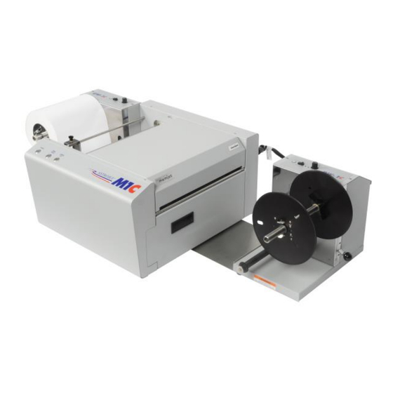
- Page 1 AstroJet™ M1C HIGH SPEED COLOR LABEL AND TAG PRINTER OPERATOR MANUAL ASTRO MACHINE CORP. 630 Lively Blvd. Elk Grove Village, IL 60007 Phone: (847) 364-6363 Fax: (847) 364-9898 www.astromachine.com...
-
Page 2: Safety Precautions
AstroJet is a registered trademark of Astro Machine Corp. ® Memjet is a registered trademark. All other trademarks are the property of their respective holders. All rights reserved. No part of this book may be reproduced or transmitted in any form or by any means, electronic or mechanical,... -
Page 3: Table Of Contents
Replacing Ink Waste Tray Removing Jams in Printer Cleaning Shipping or Transporting M1C Printer SECTION 5 – Troubleshooting Guide Memjet Printhead Printer Appendices Appendix A – M1C Specifications Appendix B – Supplies and Optional Hardware Appendix C – Borderless Printing: Overspray vs. Oversize... - Page 4 NOTES ______________________________________________________ ______________________________________________________ ______________________________________________________ ______________________________________________________ ______________________________________________________ ______________________________________________________ ______________________________________________________ ______________________________________________________ ______________________________________________________ ______________________________________________________ ______________________________________________________ ______________________________________________________ ______________________________________________________ ______________________________________________________...
-
Page 5: Section 1 - Getting Acquainted
SECTION 1 GETTING ACQUAINTED SECTION 1 – Getting Acquainted Front View Top Cover – Provides access to Print Engine. Front Cover – Provides access to Ink Tanks and Service Station. Winder Interface Connection – Winder Interface Cable plugs in here. Service Port –... -
Page 6: Rear View
SECTION 1 GETTING ACQUAINTED Rear View ON/OFF LED Button – Use to turn power ON or OFF during idle time and maintenance. Print/Pause LED Button – Press to stop printing, press to restart printing. Press switch to continue printing. Cancel/Cut LED Button – Press switch to cancel the job being printed. Also activates cutter to cut labels or roll at point desired. -
Page 7: Print Engine View
Ink Revolver Couplings – Connect ink hoses to Printhead Cartridge. Printhead Latch extends and retracts couplings from Printhead. ® Printhead Cartridge – Memjet Printhead produces an 8.5" wide full color print area. Clamshell Latches – Lift both latches at same time to open top half of Print Engine. -
Page 8: Ink Tank View
SECTION 1 GETTING ACQUAINTED Ink Tank View Cutting Blade Assembly – Cuts media after each piece or at end of a job. Ink Tank Latches – Hold Ink Tanks in place. Ink Tank Dock – Holds 5 Ink Tanks. (Ink Tanks shown installed). Ink Waste Tray –... -
Page 9: Uw-1C Unwinder/Roll Feeder (Optional)
SECTION 1 GETTING ACQUAINTED UW-1C Unwinder/Roll Feeder (Optional) Speed Control – Turn clockwise to speed up, counterclockwise to slow down. AUTO/Manual Mode Switch – Use to set Unwinder in Automatic or Manual Mode. Fuse – Unwinder fuse is located here. Hub Assembly –... -
Page 10: Rw-1C Winder (Optional)
SECTION 1 GETTING ACQUAINTED RW-1C Winder (Optional) Speed Control – Turn clockwise to speed up, counterclockwise to slow down. ON/OFF Switch – Use to turn Winder power ON or OFF. Fuse – Winder fuse is located here. Hub Assembly/Guide – Fits 3" cores. Spindle Lock/Guide –... -
Page 11: Control Panel Button/Led Indicators
SECTION 1 GETTING ACQUAINTED Control Panel Button/LED Indicators: 3 Control Panel buttons with LED indicators. POWER (ON/OFF) – Turns Printer power ON and OFF. Turns off power for cleaning and maintenance. PRINT/PAUSE (PAUSE JOB/RESUME) – Temporarily stops Feed or Resumes Printing. ... - Page 12 SECTION 1 GETTING ACQUAINTED LED Sequence Printer Status Recommended Control Panel Options ⃝ - Inactive Busy Signal: Maintenance Wait for process ⃝ - Inactive running to finish. Job loading ⃝ - Inactive Wait for process to ⃝ - Power Down finish.
-
Page 13: Printer Default Printing Modes
SECTION 1 GETTING ACQUAINTED Printer Default Printing Modes Printer has three default Printing Modes “Roll-to-Roll”, “Roll-to-Cut”, and “Fanfold”. What is connected or disconnected from Printer determines what mode Printer will operate in and disables or enables automatic function of Cutter. NOTE: These defaults will override any presets built into job being run. -
Page 14: Section 2 - Installing Printer
SECTION 2 INSTALLING PRINTER SECTION 2 – Installing Printer Contents of Packaging M1C Printer UW-1C Unwinder (Optional) RW-1C Winder (Optional) Includes Printer/Winder Spacer Plate, 2 shims Ink Tanks – Cyan, Magenta, Yellow, Black, Black Printhead Adjustable Media Guide AC Power Cord USB Cable Operator Manual Driver Software CD... -
Page 15: Remove Service Station Transport Tab
SECTION 2 INSTALLING PRINTER Remove Service Station Transport Tab 1. Open Top Cover. 2. Release two latches (one on either side of Print Engine). Open top half of Clamshell by lifting both levers at same time. CAUTION HOLD ONTO BOTH LATCHES WHEN OPENING AND CLOSING PRINT ENGINE CLAMSHELL COVER TO PREVENT DAMAGE. -
Page 16: Install Printer/Winder Spacer Plate (Optional Winder)
SECTION 2 INSTALLING PRINTER Install Printer/Winder Spacer Plate (Optional Winder): 1. Remove all four Printer feet. NOTE: To prevent ink from spilling or leaking, lift Printer only as high as needed to remove/replace feet. Move Printer to edge of bench or table to remove feet. -
Page 17: Install Printer Driver
SECTION 2 INSTALLING PRINTER Install Printer Driver For Printer software to operate properly, check that computer system meets these minimum requirements: Operating System: Windows 8/8.1, Windows 10 (Desktop Mode only). Windows XP, Windows Vista, Windows 7. Supports 32 and 64 bit systems. (You must have administrative privileges on system.) NOTE: Win 8, 8.1 and Windows 10 will only work in desktop mode. - Page 18 SECTION 2 INSTALLING PRINTER 3. Printer Connections. Click “Configure to print using USB”. Click “Next>”. 4. Installing Printer Software. 5. Connect Device Now. Switch Printer ON and connect USB cable. Don’t click on either button. Software will then finish installing. 6.
- Page 19 SECTION 2 INSTALLING PRINTER Install Over Network Connection, Version A Use this procedure to install the Print Driver over the Network connection. This procedure works for almost all networks that allow automatic assignment of the IP address (factory default). NOTE: Copy the 12-digit Hardware ID number listed on the Printer(s) on the label located just below the Ethernet port so you can identify the Printer(s) in a later step.
- Page 20 SECTION 2 INSTALLING PRINTER 4. Printer Connections. Click “Configure to print using the Network”. Make sure the Printer is connected to the Network. Then click “Next>”. 5. Printers Discovered. A list of available Printers opens. Check the Printer column to verify you have an MC-Series printer.
- Page 21 “MC Series (Network-1)” and a USB-configured printer “MC Series (USB)”. To open the “Toolbox” utility over an Ethernet (network) connection: Click Start, All Programs, Memjet, MC Series Driver, Toolbox. If more than one copy of the MC-Series Driver is installed, you will have to choose which device you want the Toolbox to connect to.
- Page 22 SECTION 2 INSTALLING PRINTER 4. Connect the Ethernet cable to the Ethernet port and rerun the “Install Over Network Connection, Version A” procedure again. The Printer should now appear on the “Printers Discovered” window. The Printer can still be identified by its “Hardware ID”, but the new IP address entered by your IT support person (or operator) is shown.
- Page 23 “MC Series (Network-1)” and a USB-configured printer “MC Series (USB)”. To open the “Toolbox” utility over an Ethernet (network) connection: Click Start, All Programs, Memjet, MC Series Driver, Toolbox. If more than one copy of the MC-Series Driver is installed, you will have to choose which device you want the Toolbox to connect to.
-
Page 24: Install Ink Tanks
SECTION 2 INSTALLING PRINTER Install Ink Tanks Printer uses one Printhead Cartridge and five Ink Tanks (two Black, one Cyan, one Magenta, and one Yellow). Install Ink Tanks as follows: 1. Open Printer Toolbox. Go to Start Menu and open “Toolbox”. - Page 25 SECTION 2 INSTALLING PRINTER 6. Click “Continue” on Confirm screen, then “Refresh Ink Levels” on User Interface screen. Ink colors fill in as Ink Tanks are installed. If ink colors do not fill in after a few seconds, click “Replace Ink Tanks” again and reinstall Ink Tank(s).
-
Page 26: Install Printhead Cartridge
SECTION 2 INSTALLING PRINTER Install Printhead Cartridge Printhead Cartridge is a delicate precision device. Handle with extreme care to avoid damage and issues that could degrade print quality. CAUTION Use electrostatic discharge (ESD) protection when handling. Hold Printhead Cartridge by handles ONLY. ... - Page 27 SECTION 2 INSTALLING PRINTER 2. [A] Carefully remove Printhead Cartridge from foil packaging. Tear foil at notch or cut the end with scissors. [B] Remove protective plastic cover. Hold Printhead by handle and unclip cover from Printhead. [C] Remove protective strip from Printhead Electrical Contacts.
- Page 28 SECTION 2 INSTALLING PRINTER 4. Wet Printhead Surface. (Ensures Printhead will prime correctly.) Open Top Cover. Release and lift two latches at same time to raise Print Engine Clamshell. Moisten Printhead nozzles using distilled water and a damp, lint-free cloth, wiping end to end. (Gray strip located below orange strip.) Close and latch Print Engine Clamshell.
-
Page 29: Removing Media Guide
SECTION 2 INSTALLING PRINTER Removing Media Guide Plastic Media Guide helps prevent smearing by holding down media such as roll-fed, die-cut, matrix- removed and perforated label stock. If necessary, it is easily removable by hand. 1. Open Top Cover 2. Open Print Engine Clamshell. CAUTION HOLD ONTO BOTH LATCHES WHEN OPENING AND CLOSING PRINT ENGINE CLAMSHELL TO PREVENT DAMAGE. -
Page 30: Aligning Printer With Uw-1C Unwinder And Rw-1C Winder
SECTION 2 INSTALLING PRINTER Aligning Printer with UW-1C Unwinder and RW-1C Winder Roll-to-Roll Label Printing Make sure Unwinder and Winder are properly connected to Printer and turned ON, this will disable automatic function of Cutter. (Cutter still operates manually by pressing CANCEL button). Proper alignment of Unwinder, Printer and Winder is critical to operation of Label Printer. - Page 31 SECTION 2 INSTALLING PRINTER Position Winder: 1. Align notch on Printer Spacer Plate with corresponding notch on Winder Base (as shown). When aligned, attach Spacer Plate to Winder Base with two screws (included). 2. Test Alignment. Run a job. If extreme web drifting is observed or web runs to one side, readjust Winder alignment.
-
Page 32: Connecting Printer To Optional Unwinder And Winder
SECTION 2 INSTALLING PRINTER Roll-to-Cut Label Printing Make sure Unwinder is properly connected to Printer and turned ON. Winder should be turned OFF or disconnected to enable automatic operation of Cutter. Proper alignment of Unwinder and Printer is critical to operation of Label Printer. Position Printer on a sturdy, stable level work surface with enough room to place Unwinder at feed end of Printer. -
Page 33: Loading Labels
SECTION 2 INSTALLING PRINTER Loading Labels Roll-to-Roll Printing IMPORTANT! Make sure Unwinder and Winder are connected to Printer. This ensures that Cutter's automatic cut function is disabled. (Cutter can still be engaged manually by pressing Cancel button). Printer is equipped with one Adjustable Side Media Guide. Make sure Unwinder is set to “Auto” and Winder (if used) is turned OFF and that both are connected to Printer via appropriate ports. - Page 34 SECTION 2 INSTALLING PRINTER [D] Align side edge of roll with two alignment pins on Printer and feed roll end into Print Engine. [E] Slide Adjustable Side Guide until it just touches labels. Tighten locking knob on Adjustable Side Guide. 3.
- Page 35 SECTION 2 INSTALLING PRINTER Adjusting Speed on UW-1C Unwinder and RW-1C Winder For proper media feeding and printing, adjust speed on Unwinder and Winder depending on type of media and job you are running. To speed up Unwinder and Winder, turn Speed Controls clockwise. To slow the speed, turn Control counterclockwise.
- Page 36 SECTION 2 INSTALLING PRINTER Roll-to-Cut Labels IMPORTANT! Winder must be turned OFF or disconnected from Printer and moved out of the way. This ensures that automatic cut function is enabled. Load Label Roll on Unwinder and Printer using Steps 1-2 in “Roll-to-Roll Printing” above. Then press Print button momentarily so Printer will align and pull in labels.
-
Page 37: Section 3 - Operating Printer
SECTION 3 OPERATING PRINTER SECTION 3 – Operating Printer Once Printer Driver is installed and Printhead is primed, you are ready to start printing. Set up your job and send it to Printer. Printer will start up and print. Printer Driver installed in Section 2 should be set as default driver. It is then accessible through your applications (such as Microsoft Word). - Page 38 SECTION 3 OPERATING PRINTER Create and save a Custom Size to suit your needs. Color Selection – Set Printing for Color, Composite Black (uses all colors to print Black), or Black Only (uses only Black ink). Print Speed – Determines print quality. Select Normal or Best. Normal is 1600 x 800 dpi, checking the “Half Speed”...
- Page 39 SECTION 3 OPERATING PRINTER Using Layout Tab Printing Adjustments Image Position – Left Adjustment moves image area away (-3mm left to +200mm right) from left edge of media. Top Adjustment moves image up or down (-5mm up to +200mm down) from top left corner of media used. (0.1mm increments) Max Page Width –...
-
Page 40: Color Tab
SECTION 3 OPERATING PRINTER Color Tab Color is used to adjust the color output of the Printer. Use the sliders to adjust Color Tone, Brightness and Saturation. The C, M, Y, K sliders adjust individual colors. Use Defaults to reset to 0 settings. Import/Export Tab Import/Export is used to preserve any custom Media Sizes, Watermarks and/or Print Settings you... - Page 41 SECTION 3 OPERATING PRINTER Services Tab Services allows you to: Print Configuration Page – Prints out current configuration of Printer including current Firmware Version, Network Connection, printer Serial Number and more. Print Colorbar Page – Prints type and color bands to check print quality.
-
Page 42: Using Printer Toolbox
SECTION 3 OPERATING PRINTER Using Printer Toolbox Once Printer Driver is installed, you can access Printer Toolbox. Toolbox lets you check printer status, monitor ink usage, perform diagnostic checks, print reports and run maintenance tasks on Printer from your computer. To open Toolbox: Open Start Menu, then click on Toolbox. - Page 43 SECTION 3 OPERATING PRINTER MAINTENANCE buttons: Circulate Ink – Purges air from lines and primes system after replacing Ink Tanks or Printhead Cartridge. Quick Clean Printhead – Circulates ink, wipes and cleans Printhead Cartridge. Normal Clean Printhead – Runs cleaning and wiping routine twice for better flushing and cleaning. Full Clean Printhead –...
- Page 44 SECTION 3 OPERATING PRINTER Mid Job Servicing – Sets frequency of automatic maintenance cycles run during a job after a set amount of media is run. Settings are: Default (14m), Level 4 (100m), Level 3 (250m), Level 2 (375m), Level 1 ...
- Page 45 SECTION 3 OPERATING PRINTER [D] Display Language – Selects language EWS (Toolbox) will display. Click “Submit” after selecting language. [E] Firmware Download – Get latest version of firmware for your Printer. NOTE: This is an alternative method for downloading firmware. See “Updating Firmware”...
- Page 46 SECTION 3 OPERATING PRINTER Diagnostics From this screen you can see current status of your Printer. You can also: Print Setup Page – Prints a printing pattern used for positioning an image on the page. Print Printhead Test – Prints color bands, text and patterns to check condition of Printhead's ink nozzles.
- Page 47 SECTION 3 OPERATING PRINTER Ink Usage Allows you to monitor estimated amount of ink left in each Ink Tank. Monitor ink use and consumption and schedule Tank changes (saving down- time during a print run.) NOTE: Ink Usage only works when you install a new Ink Tank and leave it in Printer.
- Page 48 SECTION 3 OPERATING PRINTER Network Configuration Permits you to view, enter or change settings to connect Printer to your network. Network Connection Set Up: 1. Printer is still connected to computer via USB cable. To connect Printer to a network, open Toolbox. On User Interface page, click “Network Config.”...
-
Page 49: Updating Firmware
Printer, download “*.bin” file and save it to your desktop. 2. From Start Menu, open All Programs. Open “Memjet” folder, then “MC Series Driver”. Click “Update Firmware”. 3. Click “Browse” button. Find and select file you just saved to your desktop. -
Page 50: Section 4 - Maintenance
SECTION 4 MAINTENANCE SECTION 4 – Maintenance This section covers how to care for Ink Tanks, Printhead Cartridge, and Service Station, how to clear paper jams and replace Sheet Separators. Replacing Ink Tanks Replace Ink Tanks when ink runs out. 1. -
Page 51: Cleaning Ink Tank Contacts
SECTION 4 MAINTENANCE 6. Click “Continue” on Confirm screen, then “Refresh Ink Levels” on User Interface screen. Ink colors fill in as Ink Tanks are installed. If ink colors do not fill in after a few seconds, click “Replace Ink Tanks” again and reinstall Ink Tank(s). - Page 52 SECTION 4 MAINTENANCE 2. Open Front Cover, release Ink Tank Latch(es) [A] required and remove Ink Tank(s) [B] with levels that did not refresh. 3. Clean Ink Level Prism [A] and QA Chip contacts [B] with a clean, dry, lint-free cloth. NOTE: Dampen cloth with distilled water to wipe Prism, but DO NOT get QA Chip contacts wet.
-
Page 53: Cleaning/Replacing Printhead Cartridge
SECTION 4 MAINTENANCE Storage New Ink Tanks should be stored in original packaging and kept away from heat. Opened Ink Tanks should remain in Printer. Nominal Ink expiration date: 24 months following date of manufacture (ink fill date). Disposal Safely dispose of Ink and Ink Tanks in accordance with local/national regulations. Clean up spills with soap and water. - Page 54 SECTION 4 MAINTENANCE Replacing Printhead Cartridge 1. Open Printer Toolbox. System Status information is in upper left corner of User Interface screen. 2. Open Top Cover. Open Printhead Latch [1] using Printhead Release button in Printer Toolbox. Printer pumps any ink in system back into Ink Tanks.
- Page 55 SECTION 4 MAINTENANCE 4. [A] Carefully remove Printhead Cartridge from foil packaging. Tear foil at notch or cut the end with scissors. [B] Remove protective plastic cover. Hold Printhead by handle and unclip cover from Printhead. [C] Remove protective strip from Printhead electrical contacts.
- Page 56 SECTION 4 MAINTENANCE 6. Wet Printhead Surface. (Ensures that Printhead will prime correctly.) Open Top Cover. Release and lift two latches at same time to raise Print Engine Clamshell. Moisten Printhead nozzles using distilled water and a damp, lint-free cloth, wiping end to end. (Gray strip located below orange strip.) Close and latch Print Engine Clamshell.
- Page 57 M-Series Printhead Return Policy Return Policy and Return Procedure for Memjet Printheads for M-Series Printers: Limited Printhead Replacement Policy: M-Series Printheads are manufactured to be free from defects in materials and workmanship. However, should an M-Series Printhead display an obvious defect or exhibit a significant degradation of print quality prematurely, Printhead may be returned for replacement.
- Page 58 SECTION 4 MAINTENANCE Return Procedure: 1. Verify eligibility for return. Check page count printed by this Printhead, if page total is more than 40,000 pages, replacement policy does not apply. NOTE: This is NOT Printer page count. Make sure M-Series Printer is powered up and connected via USB or network.
- Page 59 SECTION 4 MAINTENANCE Replacing Service Station Service Station is designed provide a long service life. However, should it need to be cleaned, repaired or replaced, follow these steps. Service Station is located above Ink Tank Station. 1. Open Front Cover (hinged at bottom). Open Top Cover.
- Page 60 SECTION 4 MAINTENANCE 3. Slide Service Station out of Service Station Dock. NOTE: DO NOT pull Station all the way out until you disconnect Ribbon Cable. USEFUL TIP: Place an absorbent towel under Service Station before you remove it to catch any drips or leaks.
- Page 61 SECTION 4 MAINTENANCE 6. Slide Latch open on Service Station Circuit Board. 7. [1] Plug Ribbon Connector (blue side up) into space under Latch. [2] Close Latch. 8. [1] Slide Service Station into Service Station Dock until it touches bar. Align with tracks along sides and Guide on Service Station dock floor.
- Page 62 SECTION 4 MAINTENANCE 9. GENTLY push Service Station while turning large Gear on right side of Print Engine clockwise. Gear should engage gear on Service Station Roller and pull it in. Once Service Station starts moving, stop turning gear. 10. Power up unit, then press “Install Service Station”...
-
Page 63: Replacing Ink Waste Tray
SECTION 4 MAINTENANCE Replacing Ink Waste Tray Ink Waste Tray soaks up any excess ink that may drip from Print Engine during operation. After a period of time it may become saturated and need replacement. 1. Open Ink Tank Door. 2. -
Page 64: Cleaning
SECTION 4 MAINTENANCE Cleaning WARNING! PRINTER IS A PRECISION MACHINE. CLEAN REGULARLY TO INSURE MANY YEARS OF SERVICE. BEFORE PERFORMING ANY MAINTENANCE, DISCONNECT MACHINE FROM ITS POWER SOURCE! DO NOT REMOVE SIDE COVERS! HIGH VOLTAGES PRESENT. Clean Printer regularly to remove accumulated paper dust and ink. Depending on types of media run, paper dust may accumulate inside Printer and on Transport. - Page 65 SECTION 4 MAINTENANCE [A] Grit Rollers: Clean as needed by moistening a small hard-bristled brush or toothbrush with distilled water. DO NOT use anything other than distilled water to clean Rollers. [B] Media Sensors: Paper lint and dust may build up on Media Sensors. Use a can of compressed air or a damp (not wet) foam or lint-free cotton swab to gently swab Sensors.
-
Page 66: Shipping Or Transporting M1C Printer
SECTION 4 MAINTENANCE Shipping or Transporting M1C Printer If you have to ship or transport Printer for any reason, unit will have to be prepared. Once Printer is prepared, carefully package Printer, Printhead Cartridge, Service Station and Ink Tanks in original packaging. Deprime System 1. - Page 67 SECTION 4 MAINTENANCE Remove Service Station 1. Open Ink Tank Cover (hinged at bottom). Open Top Cover. Release two latches and open Print Engine Clamshell. Service Station will not fully eject with Clamshell closed. 2. Open Printer Toolbox. Click “Eject Service Station”. Once Printer pushes Service Station out, turn Printer OFF.
- Page 68 SECTION 4 MAINTENANCE 3. Slide Service Station out of Service Station port. NOTE: DO NOT pull Service Station all the way out until you disconnect Ribbon Cable. USEFUL TIP: Place an absorbent towel under Service Station before you remove it to catch any drips or leaks.
-
Page 69: Section 5 - Troubleshooting Guide
Label Printer. We have tried to make them as complete as possible. The best advice we can offer is to make sure that system is set up properly, plugged in, and has an adequate supply of ink before attempting to troubleshoot any problem. Memjet Printhead CONDITION PROBLEM... -
Page 70: Printer
SECTION 5 TROUBLESHOOTING Printer CONDITION PROBLEM SOLUTION Ink Tank installed, no Ink Level Ink Tank contacts dirty, Remove Ink Tank(s). Clean indication in Toolbox preventing Printer/Ink Tank prism and QA Chip contacts, communication. see Maintenance, Cleaning Ink Tank Contacts. Extra lines; losing data Database problem. -
Page 71: Appendices
WINDER Hub: 3" Dia. (76.2 mm) MEDIA SENSING Label gap, notch, tick mark Water-based ink. 5 individual 250 ml ink tanks (CMYKK) ® PRINT CARTRIDGE One Memjet Replaceable Printhead INTERFACE USB 2.0 and Ethernet ELECTRICAL 115-240 VAC, 50/60 Hz PRINTER: 21" W x 21" L x 11" H (53 cm x 53 cm x 27 cm) DIMENSIONS UNWINDER/WINDER: 17"... -
Page 72: Appendix C - Borderless Printing: Overspray Vs. Oversize
APPENDICES Appendix C – Borderless Printing: Overspray vs. Oversize MC-Series Print Driver (under Printing Preferences) offers two ways for printing to edge of media, sometimes called “borderless” or “full-bleed” printing. Each option adjusts relationship between target image, selected media size and actual media on which is it printed, but in different ways. Each option has advantages and disadvantages, especially for certain types of images. - Page 73 APPENDICES Prerequisites for Overspray Since scaling can distort the image, do not use Overspray for targets that have barcodes or text because this setting could render them unreadable. If target image is a photograph or other graphical image, scaling may not be noticeable or objectionable. Make test runs and check effect of choosing Overspray. For example, overspray for a 4"...
- Page 74 APPENDICES Page Setup for Oversize When using Oversize option, Resizing (located in Layout Tab of Driver) needs to be set to “Original Size”. Page Setup for Oversize Option Impact of Using Oversize Selecting Oversize extends Custom Sizes dimensions beyond that of actual media being printed on. Since this size extension is equal in both X- and Y- axes, there is no distortion of target image.
- Page 75 APPENDICES ADDITIONAL CONSIDERATIONS AND TIPS Some additional considerations apply to both Overspray and Oversize in certain circumstances. Minimum Label Gap and Maximum Width For both Overspray and Oversize, additional consideration and testing are required when approaching limitations for minimum label gap and maximum label width. ...
-
Page 76: Index
INDEX Adjust Core Size ............29 Import/Export Tab, Printer Driver ......36 Adjust Tension, Winder ..........31 Indicators, Control Panel ..........7 Adjusting Speed, Unwinder & Winder ..... 31 Ink Revolver Couplings ..........3 Aligning Printer w/ Unwinder & Winder ....26 Ink Revolvers ............ - Page 77 INDEX Printhead ..............3 Cleaning .............. 49 Network Installing ............. 22 Configuration ............44 Latch ..............3 Connection ............1 Removing ............62 Replacing ............49 Optional Hardware ............ 67 Return Policy ............53 Overspray vs. Oversize, Printing ......68 Return Procedure ..........
- Page 78 INDEX Troubleshooting ............65 Printer ..............66 Printhead ............. 65 Unpacking Printer ............. 10 Unwinder ..............5 Aligning w/Printer ..........26 Alignment Notch ..........5 Auto/Manual Switch ........... 28 USB Port ..............1 User Interface, Toolbox ..........38 Winder ............... 6 Aligning w/ Printer ..........
-
Page 79: Printer Maintenance Schedule
PRINTER MAINTENANCE SCHEDULE General, periodic maintenance is needed to keep the Printer in good working order. Many tasks can be performed by operators with basic supplies, no special tools needed. Other tasks should only be performed by trained service personnel. NOTE: High volume usage may require more frequent maintenance. Maintenance Supplies &... - Page 81 Copyright © 2016 ASTRO MACHINE CORP. 05/12/2016 Part Number: 200-M1C Rev. I...
Need help?
Do you have a question about the AstroJet M1C and is the answer not in the manual?
Questions and answers