Table of Contents
Advertisement
Advertisement
Table of Contents

Related Manuals for Genesis GMSDB1512L


Summary of Contents for Genesis GMSDB1512L
- Page 1 GMSDB1512L 12” Dual-Bevel Sliding Compound Miter Saw Scie à onglets coulissante à double biseau de 305 mm Sierra ingleteadora de bisel doble deslizable de 305 mm Operator’s Manual Manuel d’utilisation Manual del Operario TOLL FREE 888-552-8665 HELP LINE: www.genesispowertools.com WEBSITE:...
-
Page 2: General Safety Rules
12" DouBle-Bevel SliDing CoMpounD Miter SAw operator’s Manual SpeCiFiCAtionS • Model#:----------------------------------------------------- GMSDB1512L • Rated Power:----------------------------------------------- 120V~/ 60HZ, 15 Amp • No Load Speed:-------------------------------------------- 3,800 RPM • Blade Size: ------------------------------------------------- 12” (305mm) • Arbor Size: ------------------------------------------------- 5/8” • Bevel: ------------------------------------------------------ 45° Left and Right • Miter: ------------------------------------------------------ 50° Left and Right • Cutting Capacity (Base molding vertical against fence):---- Up to 5-1/2” • Cutting Capacity (Crown molding vertically nested):-------- Up to 6-1/4” • Max Cutting Capacity at 0° x 90°:-------------------------- H 3-1/2” x 13-3/8” • Max Cutting Capacity at 45°x90°: ------------------------- H 3-1/2” x 9-3/8” • Max Cutting Capacity at 0°x 45°: -------------------------- H 2-1/8” x 13-3/8” • Max Cutting Capacity at 45°x45°: ------------------------- H 2-1/8”x 9-3/8” • Net Weight: ------------------------------------------------- 50 Lbs • Laser: -- Class II Laser, Wave Length: 650 nm, Max Output <1.0 mw, EN60825-1:1994 Includes: Saw, 80T Carbide Tipped Blade, Hold Down Clamp, Dust Bag, Extension Wings and Blade Wrench wArning: to reduce the risk of injury, user must read and understand this operator’s manual before operating this tool. -
Page 3: Work Area Safety
wArning: read and understand all warnings, cautions and operating instructions before using this equipment. Failure to follow all instructions listed below may result in electric shock, fire and/or serious personal injury. SAVE THESE INSTRUCTIONS WORK AREA SAFETY Keep your work area clean and well lit. •... -
Page 4: Tool Use And Care
SERVICE • Have your power tool Serviced by a qualified repair person using only identical replacement parts. This will ensure that the safety of the power tool is maintained. Service your power tool periodically • . When cleaning a tool, be careful not to disassemble any portion of the tool since internal wires may be misplaced or pinched. SAVE THESE INSTRUCTIONS 12" Sliding Compound Miter Saw Operator’s Manual GMSDB1512L... -
Page 5: Extension Cords
eXtenSion CorDS grounded tools require a three wire extension cord Double insulated tools can use either a two or three wire extension cord. As the distance from the power supply outlet increases, you must use a heavier gauge extension cord. Using extension cords with inadequately sized wire causes a serious drop in voltage, resulting in loss of power and possible tool damage. Refer to the table shown below to determine the required minimum wire size. The smaller the gauge number of the wire, the greater the capacity of the cord. for example: a 14-gauge cord can carry a higher current than a 16-gauge cord. When using more than one extension cord to make up the total length, be sure each cord contains at least the minimum wire size required. If you are using one extension cord for more than one tool, add the nameplate amperes and use the sum to determine the required minimum wire size. guidelines for using extension Cords • If you are using an extension cord outdoors, be sure it is marked with the suffix “W-A” (“W” in Canada) to indicate that it is acceptable for outdoor use. • Be sure your extension cord is properly wired and in good electrical condition. Always replace a damaged extension cord or have it repaired by a qualified person before using it. • Protect your extension cords from sharp objects, excessive heat, and damp or wet areas. Recommended Minimum Wire Gauge for Extension Cords (120 Volt) Nameplate Extension Cord Length Amperes... - Page 6 Failure to follow all instructions listed below may result in electric shock, fire and/or serious personal injury. SAVE THESE INSTRUCTIONS 12" Sliding Compound Miter Saw Operator’s Manual GMSDB1512L...
- Page 7 GLOSSARY OF WOODWOKING TERMS workpiece -- A piece of wood on which the cutting operation is being performed. Anti-Kickback pawls -- Device which, when properly installed and maintained, is designed to stop the work piece from being kicked back toward the operator during the operation. Arbor- - The shaft on which a cutting tool is mounted. Bevel Cut -- A cutting operation made with an angled blade. Compound Miter Cut -- A single cut made with both a miter angle and a bevel angle. Cross Cut - - A cut or shaping operation made across the work piece. Dado -- A non-through cut which produces a square sided notch or trough in the work piece. Feather board -- A device used to help control the work piece by guiding it securely against the table or fence during any rip cut operation. Freehand -- Performing a cut without using a fence, miter gauge, fixture, hold down clamp, or other proper device to keep the work piece from twisting during the cut – not recommended. -- A sticky, sap-based residue from wood products. Heel - - Misalignment of the blade. Heel can cause binding, kickback, excessive force burning the work piece or splintering Kerf -- The amount of material removed by the blade in a through cut, or the slot produced by the blade in non-through or partial cut. Kickback -- An uncontrolled grabbing or throwing of the work piece back toward the front of the saw, associated with the work piece closing the kerf and pinching the blade or otherwise placing tension on the...
-
Page 8: Knowing Your Miter Saw
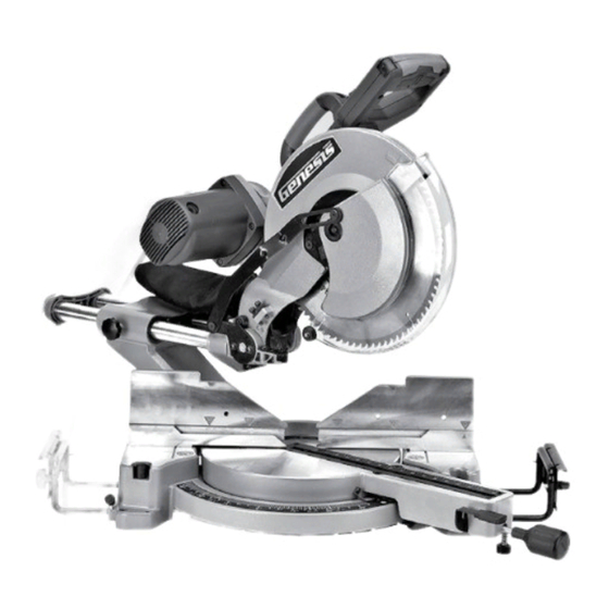
FIG 1 1. Handle 12. Sliding Miter fence 23. Laser 2. Lock-Off Switch 13. fixed Miter fence 24. Saw Head Lock Knob 3. Switch Trigger 14. Table Extension 25. Bevel Lock Handle 4. Laser Switch 15. Extension Lock Knob 26. Bevel Scale 5. Carrying Handle 16. Base 27. Blade 6. Upper Blade Guard 17. Miter Table 28. Spindle Lock Button 7. Lower Blade Guard 18. Miter Angle Pointer 29. Miter Scale 8. Motor 19. Throat Plate 30. Hold Down Work Clamp 9. Dust Bag 20. Detent Lever 10. Sliding Rails 21. Support foot 11. Slide Lock Knob 22. Miter Lock Handle 12" Sliding Compound Miter Saw Operator’s Manual GMSDB1512L... -
Page 9: Contents In Package
unpACKing AnD ContentS iMportAnt: Due to modern mass production techniques, it is unlikely the tool is faulty or that a part is missing. if you find anything wrong, do not operate the tool until the parts have been replaced or the fault has been rectified. Failure to do so could result in serious personal injury. - Page 10 Do not use thin kerf blades with deep gullets which may deflect and contact the blade guards or produce poor quality cuts in the workpiece. 12" Sliding Compound Miter Saw Operator’s Manual GMSDB1512L...
- Page 11 To Change the Blade FIG 6 1. Unplug the saw 2. Loosen the Phillips screw (1) on the blade bolt cover (2). 3. Lift up the lower blade guard (3) and the blade bolt cover(2) to expose the blade bolt. 4. Depress the spindle lock button (7) and rotate the blade until the spindle locks. 5. Using the Allen Wrench (4) provided, loosen the blade bolt (5) by turning it clockwise. Remove the blade bolt. 6. Remove the outer blade flange (6). 7. Remove the old blade off the saw. note: A blade washer may be use for the blade with arbor hole bigger than 5/8 inch. FIG 7 8. Mount the new blade carefully onto the spindle, being sure that the directional arrow on the blade surface matches the arrow on the upper blade guard. 9. Replace the outer blade flange and the blade bolt. 10. Depress and hold down the spindle lock button while tightening the blade locking bolt securely with the provided wrench in a counterclockwise direction.
- Page 12 (1). Clockwise rotation will raise the depth of cut; counterclockwise rotation will lower the depth of cut. 4. As you lower the saw blade, rotate the blade to be sure it does not contact the machine’s metal surfaces and will allow through cutting of work pieces resting against the fence. 5. Re-tighten the jamb nut while holding the adjustment bolt in place. 6. Before each use of the miter saw, with the saw unplugged, lower the blade and rotate it by hand to confirm the blade does not contact the miter saw surfaces Auxiliary Depth Control Assembly note This is useful for performing dado cuts or to create lap joints. You will need to experiment and make several test cuts until you determine the proper depth of cut. We suggest you practice on scrap wood with the same thickness dimensions before you start cutting your project wood. This unique design allows the operator to quickly engage or disengage the depth control assembly. It simply rotates on the Depth control bolt. 1. Locate the Auxiliary Depth Control Assembly (3+4) on the saw arm and on the left side of the dust port. 2. If the saw arm is locked in the down position, release it by pulling the saw arm lock knob out. 3. Rotate the Cutting Depth Stop Plate (5) to the left position. 4. Loosen the jamb nut (4) counter –clockwise several turns. 5. Use a 5mm Allen wrench to turn the Auxiliary Depth Control bolt (3). Clockwise will decrease the amount of travel and depth of cut, counter-clockwise will increase the amount of travel and depth of cut. 6. Lower the saw arm completely. The Auxiliary Depth Control Bolt will contact the Cutting Depth Stop Plate (5). Check if it is the cutting depth desired. If not, repeat step 5. 7. Once you have reached the desired cutting depth, tighten the jamb nut (4) while holding the Auxiliary Depth Control bolt in place. 8. To disable the Auxiliary Depth Control, rotate the cutting depth stop plate (5) back to the position on the right. 12" Sliding Compound Miter Saw Operator’s Manual GMSDB1512L...
- Page 13 SQUARING THE SAW BLADE TO THE FENCE (FIG 13, 14) wArning: Be sure that the tool is switched off and unplugged from the power source before performing any work on the tool. Failure to unplug the saw may result in accidental start-up, causing possible serious personal injury.
-
Page 14: Operation
To Unlock the Cutting Head 1. Press down lightly on the cutting head. 2. Pull back the lock knob (1) outwards from"Lock" position (b). FIG 18 3. Rotate the lock knob 1⁄4 turn, then release it into "unlock" position (a). 4. Slowly raise the cutting head into the work position. STARTING AND STOPPING THE MITER SAW (FIG 19) note : The saw is equipped with Lock-Off Switch on both sides of handle to provide with extra safely. 12" Sliding Compound Miter Saw Operator’s Manual GMSDB1512L... - Page 15 To start the miter saw , firm grasp the saw's top handle, use your thumb to press the Lock-Off switch (2 or 3), and then depress the switch trigger (1). To stop the miter saw, completely release the switch trigger. wArning: After completing a cut, release the switch trigger to activate the electric blade brake. Keep the cutting head down until the blade comes to a complete stop before raising the cutting head to the upward or starting position.
- Page 16 “Hazard Zone”, clamp the work piece in place and move your hand(s) to a safe position before making the cut. 12" Sliding Compound Miter Saw Operator’s Manual GMSDB1512L...
-
Page 17: Miter Crosscutting
Regardless of the type of cut being performed with your compound miter saw the following basic set-up steps are used, unless specified otherwise. 1. Check and confirm the cutting arm (bevel position) and the rotating table (miter position) are at the correct settings and the related adjustment handles are firmly locked in place. 2. Mark the position of desired cut onto the work piece surface to ensure proper blade and laser alignment. 3. Place the work piece on the saw table, align the blade and/or laser light with the cut line, then position it firmly against the fence and hold or clamp it firmly in place. If using a hand to hold the work piece in place, be sure it is outside the “Hazard Zone”. Never attempt freehand cutting or cutting a workpiece not firmly held against the fence or table! 4. Turn on the saw, allowing the blade to reach full speed. Lower the cutting head slowly into the workpiece and perform the cut at a steady rate. 5. When the cut is completed, release the switch trigger and allow the blade to completely stop rotating before raising the blade and cutting head out of the completed cut. MITER CROSSCUTTING Crosscuts are cuts made across the grain of the work piece, with a straight cut being made with the both the blade bevel and miter table set at 0°. A miter crosscut is made when the miter table is set at some angle other then 0°. 1. Measure and mark the work piece with the desired cut line. Mark the work piece on each side of the cut line indicating which side is the scrap or off cut and which the desired finished piece is. 2. Unlock the rotating miter table loosening the miter locking knob. 3. Use the miter handle to rotate the table, left or right, to the desired cutting angle. Then tighten the miter lock knob. 4. Place the work piece onto the saw table and against the fence. Turn on the laser light source. 5. Move the work piece left or right to align the cut line with the saw blade and laser light. Then secure the work piece in place, holding it either by hand for large pieces or via clamping device for small pieces. 6. After confirming the saw settings and that the work piece is secured, turn on the saw and make the cut. BEVEL CUTTING A bevel cut is made by cutting across the work piece grain with the blade angled or tilted to the work piece. When making a straight bevel cut, the miter table is set at the 0° position and the blade angled and set at a position between 0° and 45° left or right. -
Page 18: Cutting Crown Molding
Cutting Crown Molding Flat on the Miter Table (FIG 27) Since the most common corners encountered when using crown molding measure 90° inside and outside, the following instructions will be for cutting 52°/38° crown molding to fit 90° corners with the molding laying flat on the saw table. INSIDE CORNER OUTSIDE CORNER Left Side, Left Side 1. Top edge of molding against fence 1. Bottom edge of molding against fence 2. Miter table set RIGHT to 31.62° 2. Miter table set LEfT 31.62° 3. Bevel set at 33.85° Left 3. Bevel set at 33.85° Left 4. Save LEfT end of cut 4. Save RIGHT end of cut Right Side Right Side 1. Bottom edge of molding against fence 1. Top edge of molding against fence 2. Miter table set LEfT to 31.62° 2. Miter table set RIGHT 31.62° 3. Bevel set at 33.85° Left 3. Bevel set at 33.85° Left 4. Save LEfT end of cut 4. Save RIGHT end of cut 12" Sliding Compound Miter Saw Operator’s Manual GMSDB1512L... - Page 19 note: When cutting and installing crown molding keep in mind the bevel and miter angles involved are extremely accurate while the corners you’ll be working on will rarely measure exactly 90°. Therefore, be prepared to make numerous practice cuts with scrap molding to help fine tune your saw settings. for cutting crown molding flat for the corner other then 90°, please refer to Crown Molding Miter Angles chart. Cutting Crown Molding Vertically Nested Against Miter Fence (FIG 29 ) Always use a crown molding fence when cutting crown molding angled against the fence. Cutting crown molding angled against the fence does not require any special bevel settings. Small changes in the miter angle can be made without affecting the bevel angle. When using this method the saw can be quickly and easily adjusted for corners that are not 90° (square).
- Page 20 27.74/30.78 31.13/27.34 12.96/16.02 14.81/14.34 27.32/30.43 30.68/27.03 12.63/15.64 14.43/14.00 26.91/30.08 30.24/26.73 12.30/15.25 14.06/13.65 26.50/29.73 29.80/26.42 11.97/14.87 13.68/13.31 26.09/29.38 29.36/26.12 11.64/14.48 13.31/12.97 25.69/29.02 28.92/25.81 11.31/14.09 12.94/12.62 25.29/28.67 28.48/25.50 10.99/13.71 12.57/12.28 24.78/28.31 28.05/25.19 10.66/13.32 12.20/11.93 12" Sliding Compound Miter Saw Operator’s Manual GMSDB1512L...
-
Page 21: Cutting Compound Miters
CUTTING COMPOUND MITERS To aid in making the correct settings, the compound angle setting chart below has been provided. Since compound cuts are the most difficult to obtain the accuracy, make trial cuts on scrap material prior to making your required cut. NUMBER OF SIDES PITCH M-45.00° M-36.00° M-30.00° M-25.71° M-22.50° M-20.00° M-18.00° 0° B- 0.00° B- 0.00° B- 0.00° B- 0.00° B- 0.00° B- 0.00° B- 0.00° M-44.89° M-35.90° M-29.91° M-25.63° M-22.42° M-19.93° M-17.94° 5° B- 3.53°... -
Page 22: Maintenance
Do not at any time let brake fluids, gasoline, petroleum-based products, penetrating oils, etc., come in contact with plastic parts. Chemicals can damage, weaken or destroy plastic which may result in serious personal injury. Electric tools used on fiberglass material, wallboard, spackling compounds, or plaster are subject to accelerated wear and possible premature failure because the fiberglass chips and grindings are highly abrasive to bearings, brushes, commutators, etc. Consequently, we do not recommended using this tool for extended work on these types of materials. However, if you do work with any of these materials, it is extremely important to clean the tool using compressed air. LUBRICATION This tool is permanently lubricated at the factory and requires no additional lubrication. 12" Sliding Compound Miter Saw Operator’s Manual GMSDB1512L... -
Page 23: Two Year Warranty
This product is warranted free from defects in material and workmanship for 2 years after date of purchase. This limited warranty does not cover normal wear and tear or damage from neglect or accident. The original purchaser is covered by this warranty and it is not transferable. Prior to returning your tool to store location of purchase, please call our Toll-free Help Line for possible solutions. ACCESSORIES INCLUDED IN THIS KIT ARE NOT COVERED BY THE 2 YEAR WARRANTY. toll-Free Help line 888-552-8665 for questions about this or any other GENESIS™ Product, please call Toll-free: www.genesispowertools.com Or visit our web site: ©richpower industries, inc. All rights reserved Richpower Industries, Inc. 736 Hampton Road Williamston, SC 29697 Printed in China, on recycled paper... - Page 24 Richpower Industries, Inc. 736 Hampton Road Williamston, SC USA www.richpowerinc.com 2012.06.25 v. 01...
Need help?
Do you have a question about the GMSDB1512L and is the answer not in the manual?
Questions and answers