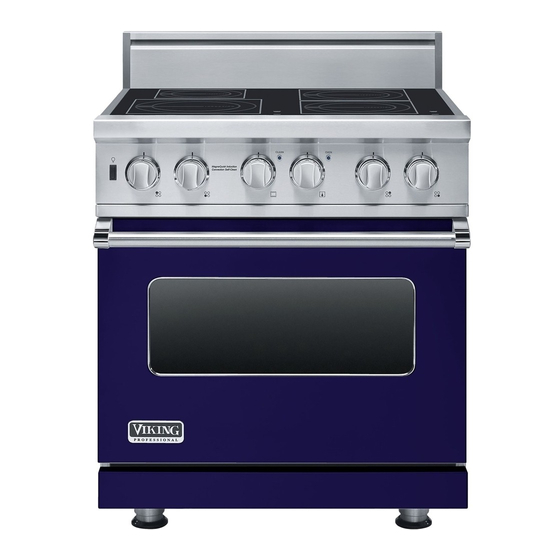
Viking VISC530 Service Manual
Electric induction range
Hide thumbs
Also See for VISC530:
- Manual (48 pages) ,
- Use & care manual (32 pages) ,
- User manual (28 pages)
Table of Contents
Advertisement
Quick Links
Service
Preferred Service
Manual
This manual is to be used by qualified appliance technicians only.
Viking does not assume any responsibility for property damage
or personal injury for improper service procedures done by an
unqualified person.
Professional
30" Electric
This manual covers general and
specific information including, but not
Induction Range
limited to the following model:
VISC530
SMC-0011
May 2009
Advertisement
Table of Contents

Related Manuals for Viking VISC530


Summary of Contents for Viking VISC530
- Page 1 Service Preferred Service Manual This manual is to be used by qualified appliance technicians only. Viking does not assume any responsibility for property damage or personal injury for improper service procedures done by an unqualified person. Professional 30" Electric This manual covers general and specific information including, but not...
-
Page 2: Table Of Contents
Input and Output ..........51 Control Board Input ..........52 SERVICE DIAGNOSTICS AND PROCEDURES– Control Board Output ..........52 DISASSEMBLY Wiring Diagram VISC530 ........53 Parts Location–Range Back ........20 Parts Location–Range Front and Oven Cavity ..21 Parts Location–Control Board .........22 Access Control Board Assembly ......23 Control Board Removal ..........23... -
Page 3: Important Information
“DANGER”, “WARNING” or “CAUTION”. These words mean: CAUTION DANGER VIKING will not be responsible for any injury or property damage from improper service Immediate hazards which WILL result in severe procedures. If performing service on your personal injury or death. -
Page 4: Warranty Information
Viking Range Corporation service agency or representative. This warranty does not apply to commercial usage. Warrantor is not responsible for consequential or incidental damage whether arising out of breach of warranty, breach of contract, or otherwise. -
Page 5: Warranty Service Information
The return of the Owner Registration Card is not a condition of warranty coverage. You should, however, return the Owner Registration Card so that Viking Range Corporation can contact you should any question of safety arise which could affect you. -
Page 6: General Information
( 2 . (20.3 cm) min. 37” (94 cm) max. ( 9 1 - 7 / 8 ” i n . ( 9 4 ” 19-3/8” 25-3/4” (65.4 cm) (49.2 cm) 45-1/8” (114.6 cm) 24-5/16” (61.8 cm) © 2009 Viking Preferred Service... -
Page 7: Warnings
Some cleaners can produce noxious fumes if applied to a hot surface. © 2009 Viking Preferred Service... - Page 8 WARNING Burn Or Electrical Shock Hazard Make sure all controls are OFF and oven is COOL before cleaning. Failure to do so can result in burns or electrical shock. © 2009 Viking Preferred Service...
- Page 9 When the insulation is thoroughly cured, this odor will disappear. During subsequent self-cleaning cycles, you may sense an odor characteristic of high temperatures. KEEP THE KITCHEN WELL-VENTED DURING THE SELF-CLEAN CYCLE. © 2009 Viking Preferred Service...
-
Page 10: Induction Cookware
General Information Cookware Each cook has his or her own preference for the All Viking cookware is induction friendly, as are particular cookware that is most appropriate for most other high-end brands of stainless steel and the type of cooking being done. This a matter enamel cookware. -
Page 11: Model - Serial Number Matrix
V I S C 5 3 0 4 B S S V=Professional Series Stainless Steel Induction Four Burner 30” Wide Self Clean Custom Series Serial Numbers 02 10 09 C00006566 Month Serial Number Year of Manufacture © 2009 Viking Preferred Service... -
Page 12: Operation
Built-In Error Codes section Note: Viking induction cooking uses high powered page 16. induction elements for faster cooking performance. Some noise may be noticed by the high powered induction elements. -
Page 13: Using The Oven
CONV BAKE (Convection Bake) recommended. The Viking Rapid Ready™ Preheat Use this setting to bake and roast foods at the same System is engineered so that the oven is brought time with minimal taste transfer. -
Page 14: Cleaning And Maintenance
These products could remove the graphics from the control panel. Apply hot, soapy water to a soft clean cloth. DO NOT spray liquids directly onto the control panel. © 2009 Viking Preferred Service... -
Page 15: Self Clean Cycle
If the range is in the self-clean cycle when the power failure occurs, wait until power is restored and allow door to unlock automatically. Turn all controls off and restart self-clean cycle again, according to instructions. © 2009 Viking Preferred Service... -
Page 16: Diagnostics
filter board Communication error Interface board Replace interface board between interface board Interface board cable loose or Check connection of cable and and induction generator defective replace cable if needed Filter board Replace filter board © 2009 Viking Preferred Service... - Page 17 – Display of the residual No failure Cooking zone needs to cool down heat Temperature over 60˚ C in a cooking zone switched OFF). and off until the zone has cooled. © 2009 Viking Preferred Service...
-
Page 18: Led Error Codes
The electromagnetism is generated by electronics in the inductor under the main top glass. When a good- Metal to be heated– work piece (secondary) © 2009 Viking Preferred Service... -
Page 19: How Induction Works
Inductors Magnetic energy There is one point about induction cooking with current technology that needs to be made. The cooking vessel being used must be of a ferrous material, a magnet will stick to it. © 2009 Viking Preferred Service... -
Page 20: Service Diagnostics And Procedures
Service Diagnostics and Procedures Parts Location—Range Back Induction Module Cooling Fan Oven Cooling Fan Broil Element Oven Sensor Convection Terminal Block Element © 2009 Viking Preferred Service... -
Page 21: Parts Location-Range Front And Oven Cavity
Service Diagnostics and Procedures Parts Location–Contol Panel and Oven Cavity Induction Switch Thermostat Selector Smoke Eliminator Broil Element Oven Light Oven Light Convection Fan Cover © 2009 Viking Preferred Service... -
Page 22: Parts Location-Control Board
Service Diagnostics and Procedures Parts Location–Oven Control Board High Limit Jumper Door/Light Switches © 2009 Viking Preferred Service... -
Page 23: Access Control Board Assembly
3. Remove ten screws and control board from lower mounting plate. Note: During installation, make sure the tabs on the control panel are aligned with the slots on the range. Reverse procedure for installation. 4. Reverse procedure for installation. © 2009 Viking Preferred Service... -
Page 24: Control Board Diagnostics
38 should the element is miswired. Ω be found. If either element fails to read resistance, remove the element to repair or replace as shown on page 34. © 2009 Viking Preferred Service... - Page 25 19 . If the element fails to read replace as shown on page 32. Ω resistance, remove the element to repair or replace as shown on page 36. © 2009 Viking Preferred Service...
- Page 26 P1 connector (forward direction). replace as shown on page 35. The resistance should be approximately 100 . If Ω no resistance is read, remove the fan to repair or replace as shown on page 33. © 2009 Viking Preferred Service...
- Page 27 Ω Ω 5VDC 6.71K 3.90VDC 2.43K 1.14VDC Medium Broil 9.10K Ω Ω Ω Low Broil 9.10K 5VDC 7.76K 4.40VDC 1.38K 0.63VDC Ω Ω Ω Self Clean 9.10K 5VDC 8.85K 4.86VDC 0.44K 0.17VDC Ω Ω Ω © 2009 Viking Preferred Service...
- Page 28 At room temperature the reading should be approximately 1050 – 1100 Ω If no or infinite resistance is read, verify sensor wiring is connected completly throught circuit. If wiring is OK replace sensor. © 2009 Viking Preferred Service...
-
Page 29: Convection Fan Assembly
K6 relay blue to grey determines the direction of the fan and K7 relay orange to green determines the fan speed. If component access is needed, see convection fan disassembly instructions (page 33). © 2009 Viking Preferred Service... -
Page 30: Thermostat
If the readings of the thermostat or sensor are out of range, replace that component. Note: The thermostat and selector can be checked from the control board assembly. © 2009 Viking Preferred Service... -
Page 31: Control Panel Assembly Removal
(label wiring and switch orientation before disassembly). 2. Remove two screws, bezel, and the oven thermostat from the control panel assembly. 5. Reverse procedure for installation. 3. Reverse procedure for installation. © 2009 Viking Preferred Service... -
Page 32: Oven Sensor
The line break relay is a device that breaks the L2 To check fan, measure the resistance and voltage. If side of line voltage. As the relay is energized, the all checks are good and the unit still stops working, replace the control board. © 2009 Viking Preferred Service... -
Page 33: Convection Fan Cover Removal
2. Pull down the smoke eliminator to remove from oven liner. Note: The mounting hole pattern for the 3. Reverse procedure for installation. convection fan assembly is NOT symmetrical. Line up holes before installing. 3. Reverse procedure for installation. © 2009 Viking Preferred Service... -
Page 34: Bake Element Removal
4. Remove bake element insulation from range. 1. Remove four screws and rack support from each side of oven cavity. Note: Use care with insulation, make sure to replace any damaged or missing insulation. 2. Reverse procedure for installation. © 2009 Viking Preferred Service... -
Page 35: Broil Element
12.3 Ω the control board is supplied. If voltage is present Apply 120 VAC to the motor and it should start to and the broil element does not energize, replace rotate. the element. © 2009 Viking Preferred Service... -
Page 36: Convection Bake Element Removal
Door Assembly Removed connectors go back through the oven liner. 1. Place oven rack in second position from top. 6. Reverse procedure for installation. 2. Remove four screws and front broil element bracket from oven cavity. © 2009 Viking Preferred Service... -
Page 37: Control Board/Bake Element Cover
Service Diagnostics and Procedures Parts Location–Range Top, Bake Element, Control Board Generators Indicator Inductors Oven Control Board Bake Element Cover © 2009 Viking Preferred Service... -
Page 38: Interface Removal
6. Reverse procedure for installation. Idicator, Inductor, Filter and Power Board Removal 1. Remove control panel (see Interface Removal steps 1 -3). 4. Interface boards are now accessible. 2. Remove two screws securing top. Screws Interface © 2009 Viking Preferred Service... - Page 39 5. Remove two screws that secure each inductor to generator cover. 8. Remove interface connection. Remove inductors from generator cover. Screws Interface Connection Note: Left and right module interface board connection CANNOT be reversed. If this occurs error code ER31 will occur. © 2009 Viking Preferred Service...
- Page 40 4. Replace the light cover by snapping glass cover onto metal box. 11. Remove generator cover. Filter and power board are now accessible. Power Board Filter Board 12. Reverse procedure to reassemble. © 2009 Viking Preferred Service...
-
Page 41: Induction Switch
ER31 will occur. Medium-Low 7850 Ω +/- 50 Ω Medium 6600 Ω +/- 50 Ω Medium-High 2840 Ω +/- 50 Ω High 9.6 Ω +/- 50 Ω Measured from positions 2 and 3 © 2009 Viking Preferred Service... -
Page 42: Interface/Induction Adapter
(Er31). © 2009 Viking Preferred Service... -
Page 43: Filter Board
PE. The filter board is protected by a 20 amp fuse located between E23 – E22. Verify 120VAC between L1 and ground, 120VAC between L2 and ground, and 240VAC between L1 and L2 at the filter board. © 2009 Viking Preferred Service... -
Page 44: Power Board
3700W. Verify power at the power board (blue to black). If power is present at power board and no output to inductor, replace power board. © 2009 Viking Preferred Service... -
Page 45: Inductor
(a common refrigerator NOTE: Replacement parts for items covered in magnet will stick to it). If the cooking vessel is this section are included in a service kit. proper, replace the inductor. © 2009 Viking Preferred Service... -
Page 46: Cooling Fan
If all checks well, replace the filter board. Test Points NOTE: Replacement parts for items covered in this section are included in a service kit. © 2009 Viking Preferred Service... -
Page 47: Component Testing Chart
0VDC P20 brown – purple (Door Closed) (P20 brown–purple) Oven Door Switch 0VDC Open P20 brown – grey (Door Open) (P20 brown–purple) Oven Door Switch 16VDC Open P20 brown – grey (Door Closed) (P20 brown–grey) © 2009 Viking Preferred Service... -
Page 48: Component Troubleshooting Guide
Replace control board Open relay No broil, oven lights Open broil element Confirm resistance operate Open or out of calibration Replace selector selector Open or out of calibration Replace thermostat thermostat Open relay Replace control board © 2009 Viking Preferred Service... - Page 49 Light bulb is burned out Check bulb and replace if defective Supply voltage Verify source voltage Blower motor inoperable Open blower motor Check blower resistance Oven Sensor Ohm oven sensor Open relay Replace control board © 2009 Viking Preferred Service...
-
Page 50: Filter Board Input And Output
Power Board Input and Output Filter Board Communication Power Output input from to LF/RF inductor filter board Input from LF/RF Input from thermal sensor filter board Power Output to LR/RR inductor Power Board Input from LR/RR thermal sensor © 2009 Viking Preferred Service... -
Page 51: Induction Switch/Interface/Indicater Input And Output
Line signal output to filter board (X68) Input from Induction Switch Indicator LED signal from interface LED signal from interface *Caution do not swap Interface Boards/Induction Adapters or you will get an Interface error (Er 31). © 2009 Viking Preferred Service... -
Page 52: Control Board Input
(P4-1) Forward fan direction (P4-2) Reverse fan direction (P4-3) Out to fan–Lo Speed Outer Bake (P4-3) Out to fan–Hi-Speed (P5-2) Out to outer bake element (P5-4) Out to inner bake element (P11) Out to cooling fan Inner Bake © 2009 Viking Preferred Service... -
Page 53: Wiring Diagram Visc530
Wiring and Schematics *Caution do not swap Interface Boards/Induction Adapters or you will get an Interface error (Er 31). © 2009 Viking Preferred Service...