Table of Contents
Advertisement
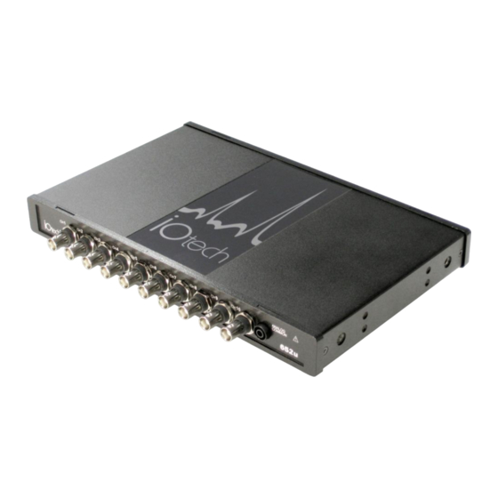
IOtech 652u
10 Channel Dynamic Signal Analyzer for
Vibration Analysis and Monitoring
IOtech 652u
1170-0901
1.0
rev
*372562A-01*
372562A-01
USER'S MANUAL
Requires one of the following
Operating Systems:
Windows 2000 SP4
Windows XP
Windows Vista
25971 Cannon Road
Cleveland, OH 44146-1833
(440) 439-4091
Fax: (440) 439-4093
sales@iotech.com
productsupport@iotech.com
www.iotech.com
IOtech
Advertisement
Table of Contents

Subscribe to Our Youtube Channel
Related Manuals for IOtech 652u


Summary of Contents for IOtech 652u
- Page 1 USER’S MANUAL IOtech 652u 10 Channel Dynamic Signal Analyzer for Vibration Analysis and Monitoring Requires one of the following Operating Systems: Windows 2000 SP4 Windows XP Windows Vista IOtech IOtech 652u 25971 Cannon Road 1170-0901 Cleveland, OH 44146-1833 (440) 439-4091...
-
Page 2: Warranty Information
IOtech, Inc. cannot be held liable for any damages resulting from the use or misuse of this product. Copyright, Trademark, and Licensing Notice All IOtech documentation, software, and hardware are copyright with all rights reserved. No part of this product may be copied, reproduced or transmitted by any mechanical, photographic, electronic, or other method without IOtech’s prior written consent. -
Page 3: Table Of Contents
Table of Contents Quick Start Chapter 1 – What is the IOtech 652u? Chapter 2 – Block Diagram Chapter 3 – Connectors, Indicators, and Cables Front Panel (Analog) Connectors …… 3-1 Introduction …. 3-1 Analog Common …… 3-1 Current Source (IEPE) with Transducer Fault Detection ……. 3-1 Input Coupling ……... - Page 4 This page is intentionally blank. IOtech 652u User’s Manual 956991...
-
Page 5: Quick Start
Step 2 - Connect the 652u to Power and to the Computer Supply power from the TR-2U to the 652u before connecting the USB cable to the computer. This allows the 652u to inform the host computer (upon connection of the USB cable) that the unit requires minimal power from the computer’s USB port. - Page 6 Electric shock or damage to equipment can result even under low-voltage conditions. Take ESD precautions (packaging, proper handling, grounded wrist strap, etc.) The 652u has 10 analog channel inputs (CH1 through CH10) via front panel BNC connectors and 8 digital I/O lines via rear panel DB9 connector. Digital I/O...
-
Page 7: Chapter 1 - What Is The Iotech 652U
Many other systems do not offer continuous time-domain transfer to the PC, and as a result the waveform length is limited by the amount of built-in data storage. In regard to our 652u, the only limitation is the amount of available hard disk memory on the host PC, or that which can be accessed by a PC on a network. - Page 8 8 Digital I/O Channels: DB9 connector for connection of Digital I/O signal lines. Note: eZ-NDT or eZ-TOMAS software must be used to make use of the Digital I/O. Analog Channel Triggering Pre- and Post-Trigger Readings What is the IOtech 652u? IOtech 652u User’s Manual 938791...
-
Page 9: Chapter 2 - Block Diagram
Block Diagram IOtech 652u Block Diagram IOtech 652u User’s Manual Block Diagram 948491... - Page 10 Chapter 3, Connectors, Indicators, and Cables. USB2.0 The IOtech 652u transfers acquired data to the PC via a USB2.0 connection. It is important to note that USB ports and USB hubs cannot supply sufficient power to a 652u.
-
Page 11: Front Panel (Analog) Connectors
The front panel includes ten BNC connectors for voltage input. These are labeled CH1 through CH10. The front panel also includes analog common. The IOtech 652u includes circuitry for dynamic analog signal conditioning. The circuitry typically interfaces with piezoelectric transducers that include, but are not limited to: accelerometers, microphones, tachometers, and force/pressure transducers. -
Page 12: Current Source (Iepe) With Transducer Fault Detection
Refer to the specifications chapter for details, including a response chart. Analog Triggers The IOtech 652u signal analyzer can be triggered per software configuration relevant to the 10 analog input channels. Refer to the associated software documentation regarding the various types of triggers and how to set them. -
Page 13: Rear Pannel Connectors And Indicators
Asynchronously, the digital I/O can be either read or written to, as opposed to the synchronous mode, which is read- only. Points to note: To use the 652u’s Digital I/O, the host PC must have eZ-TOMAS software installed. All configurations pertaining to Digital I/O are controlled by software and can be updated by the software at any time. -
Page 14: Machine Screw (Chassis To Earth Ground)
5 are 1m, 3m, and 5m in length, respectively. The IOtech 652u transfers acquired data to the PC via USB. When a computer has a board with USB 2.0 ports, an “Enhanced” USB controller can be found in the Device Manager. The Device Manager will also show two other USB controllers due to the fact that USB2.0 circuitry includes 3 chips [one for the actual USB2.0 capable devices and two for... -
Page 15: Overview
CE Standards and Directives …… 4-1 Safety Conditions ……4-2 Emissions/Immunity Conditions ……4-3 CE Rules of Thumb for 652u …… 4-3 Noise Considerations …… 4-4 Overview CE compliant products bear the “CE” mark and include a Declaration of Conformity stating the particular specifications and conditions that apply. -
Page 16: Safety Conditions
Voltages above 30 Vrms or ±60 VDC must not be applied if any condensation has formed on the device. Current and power use must not exceed specifications. Do not defeat fuses or other over-current protection. CE-Compliance & Noise Considerations 652u User’s Manual 957791... -
Page 17: Emissions/Immunity Conditions
RF fields or transients over 3 or 10 V/m as noted on the Declaration of Conformity. CE Rules of Thumb for 652u IOtech 652u units are CE Compliant at the time they leave the factory and should remain in compliance as long as the conditions stated on the Declaration of Conformity continue to be met. -
Page 18: Noise Considerations
Make a solid earth ground connection. Using insulated low resistance wire, connect the 652u chassis (via the rear panel #6-32 machine screw) to solid earth ground. This practice: (a) keeps radiated emissions low by keeping the chassis electrically quiet,... - Page 19 Non-Destructive Test Software …… 5-5 eZ-NDT ** This chapter offers a glimpse of the eZ software packages that can be used with an IOtech 600 series device, with exceptions as noted. The software is usually purchased when the hardware is ordered; but should your acquisition needs change, additional software packages can be ordered at a later time.
-
Page 20: Ez-Analyst
This software adds real-time continuous and transient data acquisition to an IOtech 600 series system. Analysis can be in the time, frequency, or order domain. -
Page 21: Ez-Tomas
An IOtech 600 series system running with eZ-TOMAS can be easily moved from machine to machine with very short setup times. You can use the system to reduce downtime, improve data collection, troubleshoot, and recondition the machine. -
Page 22: Ez-Balance
Rotating Machine Balancing An IOtech 600 series system using eZ-Balance provides a solution for multi-plane field balance applications of rotating machinery. eZ-Balance computes the optimal balance weights and their locations, based on vibration data collected from the analyzer. The data is displayed in a convenient Polar plot that indicates the magnitude and phase of the unbalance as well as time and spectrum data. -
Page 23: Ez-Ndt
(non-destructive test) uses resonance to identify part variations caused by process inconsistencies and defects. Using eZ-NDT with an IOtech 600 series device is a fast and inexpensive method for performing 100% inspection of production parts. Inspection parts include, but are not limited to: powder metal, ceramics, and composites. - Page 24 This page is intentionally blank. 5-6 Software Options 652u User’s Manual 928291...
-
Page 25: Chapter 6 - Product Care And Customer Support
ESD bags and cartons, and related procedures. Product Care IOtech 652u is essentially maintenance free and requires only a minimal amount of care. The 652u should be treated much like any other high-tech piece of equipment. In general: The units should be operated in ventilated and relatively dust-free environments. -
Page 26: Readme Files And The Install Cd-Rom
Note: Before calling for assistance, take a few minutes to read all parts of the manual that may be relevant to the problem. Also, please review the troubleshooting material. You can reach IOtech by one of the following means: Phone:... -
Page 27: General Specifications
Specifications – IOtech 652u Section 7.b, Specifications, Data Plots, contains a great deal of information in the form of plotted data. References to the plots appear in this section (7.a) when applicable. General Specifications Environment: Operating Temperature: -40˚ to 60˚C Humidity: 0˚... - Page 28 Typical Noise* Frequency (µV rms) (Hz) 1000 2000 5000 10000 20000 40000 aximum noise @ <50°C = 1.4x; @> 50°C = 2.1x (where x is the typical value given in the above table). 7.a-2 Specifications IOtech 652u User’s Manual 927791...
- Page 29 High: >3.0V with no load Sampling: 105,468Hz, maximum Input / Output Circuit Note: A Digital I/O example is located in section 7.b. Figure 13. Digital I/O I-V Curve Output timing: Outputs are always written asynchronously. IOtech 652u User’s Manual Specifications 7.a-3 927791...
- Page 30 Specifications are subject to change without notice. This page is intentionally blank. 7.a-4 Specifications IOtech 652u User’s Manual 927791...
- Page 31 Phase-Matching vs. Frequency, AC-Coupled ………. Fig. 11 Typical CMRR …………………………………………… Fig. 12 Digital I/O I-V Curve …………………………………….. Fig. 13 Fig. 1 Measurement High Pass Filter Response 0.01 0.10 1.00 10.00 Frequency IOtech 652u User’s Manual Specifications, Data Plots 7.b-1 957091...
- Page 32 -500.0E-9 -1.0E-6 -1.5E-6 -2.0E-6 10000 20000 30000 40000 50000 Frequency (Hz) Fig. 3 Measurement Delay vs Frequency AC-Coupled 5.0E-6 4.0E-6 3.0E-6 2.0E-6 1.0E-6 000.0E+0 10000 20000 30000 40000 50000 Frequency (Hz) 7.b-2 Specifications, Plotted Data IOtech 652u User’s Manual 957091...
- Page 33 Sample Rate = 26368 samples per second -100 -120 2,000,000 4,000,000 6,000,000 8,000,000 10,000,000 Frequency (Hz) Fig. 5 Antialiasing Filter & Analog Input Circuit Response 1,000 10,000 100,000 1,000,000 10,000,000 Frequency IOtech 652u User’s Manual Specifications, Plotted Data 7.b-3 957091...
-
Page 34: High Frequency Artifacts
4,000 5,000 6,000 7,000 8,000 9,000 10,000 Frequency (kHz) Fig. 7 Measurement THD+N ________ DC Coupled - - - - - - AC Coupled -100 -105 -110 1,000 10,000 100,000 Frequency 7.b-4 Specifications, Plotted Data IOtech 652u User’s Manual 957091... -
Page 35: Sfdr
0.06 0.04 0.02 -0.02 -0.04 Ch 1 Ch 2 Ch 3 -0.06 Ch 4 -0.08 Specification limit -0.1 1000 10000 100000 Frequency Full-Scale is +29dBV; Input is -30dBV Fig. 9 SFDR IOtech 652u User’s Manual Specifications, Plotted Data 7.b-5 957091... - Page 36 Legend Format (aggressor - victim) Fig. 11 Phase Matching vs Frequency, AC-Coupled Comparison of phase differences Spec among five channels of a representative unit -0.5 -1.0 Spec -1.5 1,000 10,000 100,000 Frequency (Hz) 7.b-6 Specifications, Plotted Data IOtech 652u User’s Manual 957091...
-
Page 37: Fig. 12
& hollow symbol = DC coupled thick line solid symbol = AC coupled -100 -120 1,000 10,000 100,000 Frequency Fig. 13 Digital I/O I-V Curve Digital Output Digital Output High Digital Input Volts IOtech 652u User’s Manual Specifications, Plotted Data 7.b-7 957091... - Page 38 Specifications are subject to change without notice. This page is intentionally blank. 7.b-8 Specifications, Plotted Data IOtech 652u User’s Manual 957091...
- Page 39 Device Manager DaqX PnP Devices You will see the device listed in the format of 652u as in the following figure. You can now change the device name from the 652u default to a “friendly” name. 1. Right-click on the device name (preceding figure). This opens its properties dialog box.
- Page 40 This page is intentionally blank. Appendix A – Device Name 652u User’s Manual 957581...
Need help?
Do you have a question about the 652u and is the answer not in the manual?
Questions and answers