Table of Contents
Advertisement
Advertisement
Table of Contents

Subscribe to Our Youtube Channel
Related Manuals for Holip HLP-NV Series


Summary of Contents for Holip HLP-NV Series
- Page 2 HLP-NV Series...
-
Page 4: Table Of Contents
HLP-NV Series I. Introduction 1. Checks upon Delivery 2. Nameplate Description of HLP-NV Series Inverter II. Safety Precautions 1. Before the Power-up 2. During the Power-up 3. During the Operation 4. After the Power-off III. Standards and Specifications 1. Particular Specifications 2. - Page 5 HLP-NV Series IX. Appendices Appendix 1: Mounting Dimensions of HOLIP NV inverters Appendix 2: Mounting Dimensions of LCP Digital operator Appendix 3. Braking Resistor Disposition Appendix 4. Simple Example of Appliaction Appendix 5:User’s feedback HLP-NV Series...
-
Page 6: I. Introduction
I. Introduction Thank you for purchasing and using the general-purpose inverter of HLP-NV series of multi-functions and high performance. Please read carefully the operation manual before putting the inverter to use so as to correctly install and operate the inverter, give full play to its functions and ensure the safety. -
Page 7: Checks Upon Delivery
● Check if the inverter has got any damage or deformation during the transportation and handling. ● Check if there is one piece of HLP-NV series inverter and one copy of the instruction manual available when unpacking it. ● Check the information on the nameplate to see if the specifications meet your order (Operating voltage and KVA value). -
Page 8: Nameplate Description Of Hlp-Nv Series Inverter
HLP-NV Series 2. Nameplate Description of HLP-NV Series Inverter Model HLP NV 0D75 23 A Software Version: A Voltage Rating: 21:1-Phase AC 220V 23:3-Phase AC 220V 43:3-Phase AC 380V Inverter Capacity:0 D 75 means 0.75KW Serial No: NV means NV series... -
Page 9: Ii. Safety Precautions
HLP-NV Series II. Safety Precautions 1. Before the Power-up Caution ● Check to be sure that the voltage of the main circuit AC power supply matches the input voltage of the inverter. ● The symbol , represents ground terminals. Be sure to make correct ground connection of the earth terminals of the motor and the inverter for safety. - Page 10 HLP-NV Series ● Be su re to t u r n off the power supply before dissembling or assembling the operation keypanel and fixing the front cover to avoid bad contact causing faults or non-display of the operator. ● Do not install the inverter in a space with explosive gas to avoid the risk of explosion.
-
Page 11: During The Power-Up
HLP-NV Series 2. During the Power-up Danger ● Do not plug the connectors of the inverter during the power up to avoid any surge into the main control board due to plugging, which might cause the damage of the inverter. -
Page 12: After The Power-Off
HLP-NV Series 4. After the Power-off ● Touching the electrical parts may be fatal - even after the equipment has been disconnected from mains. Also make sure that other voltage inputs have been disconnected, (linkage of DC intermediate circuit). ● Be aware that there may be high voltage on the DC link even when the LEDs are turned off. -
Page 13: Iii. Standards And Specifications
HLP-NV Series III. Standards and Specifications 1. Particular Specifications Output Suitable Power Model Input Voltage Current Motor (KW) (KW) HLPNV0D1821A 1×200-240V 50/60Hz 0.18 0.18 HLPNV0D3721A 1×200-240V 50/60Hz 0.37 0.37 HLPNV0D7521A 1×200-240V 50/60Hz 0.75 0.75 HLPNV01D521A 1×200-240V 50/60Hz HLPNV02D221A 1×200-240V 50/60Hz HLPNV0D2523A 3×200-240V 50/60Hz... -
Page 14: General Specifications
HLP-NV Series 2. General Specifications Inverter Series HLP-NV Frequency 48~62HZ Power 380~480V±10% for 380V ; supply Supply Voltage single/three phase 200~240V±10% for 220V Output voltage 0~100% of supply voltage 0-200HZ(VVC+), Output frequency Motor 0-400HZ(V/F) output Over load 150% of rated current Acc/Dec time 0.05~3600s... - Page 15 HLP-NV Series Terminal number 24V DC Max.load 200mA RS+(TX+,RX+), Terminal number RS- (TX-,RX-) RS 485 Ground for RS485 1,FA-FB(make), Terminal number FA-FC(break) Control 250V AC 2A terminals Resistive load Realy outpus 30V DC 2A load 250V AC 0.2A Inductive load 24V DC 0.1A...
-
Page 16: Iv. Storage And Installation
HLP-NV Series IV. Storage and Installation 1. Storage The inverter must be kept in its original package box before installation. Pay attention to the followings when keeping it in storage if the inverter is not used for the time being: ●... - Page 17 HLP-NV Series for effective cooling. ● If there is any instability when installing the inverter, please put a flat board under the inverter bottom base and install it again. If the inverter is installed on a loose surface, stress may cause damage of parts in the main circuit so as to damage the inverter.
-
Page 18: V. Wiring
HLP-NV Series V. Wiring 1. Main Circuit Wiring Schematic Diagram Power supply: ● Verify that the inverter’s rated voltage coincides with AC power supply voltage to avoid a damage of the inverter. No fuse breaker: ● Refer to the related list. -
Page 19: Description Of Terminal Block
HLP-NV Series 2. Description of Terminal Block 1 ) Arrangement of Main circuit Terminals POWER MOTOR -UDC +UDC BR ( L) Function Description of Main circuit Terminals Symbol Function Description Input terminal of AC line power. (220V class:for both R S T single/three phase, single phase connected to L and N) U.V.W... -
Page 20: Basic Connection Diagram
HLP-NV Series Default setting Symbol Function Description setting Multi- Digital Input Bit0 Multi- Analog Output 0/4-20mA +10V Power Supply for Analog Setting +10V Multi- Analog input Voltage Analog Ground Multi- Analog input 0/4~20mA FA-FC:break FA FB FC Multi- Digital Output (Relay) -
Page 21: Switches
HLP-NV Series 4. Switches i. Bus termination: BUS TER Mark:Switch BUS TER enables termination of the RS485 port, terminals RS+, RS-. ii. Switches 1-4: Switch 1: *OFF = PNP terminal JOG ON = NPN terminal JOG Switch 2: *OFF = PNP terminals RUN,... - Page 22 HLP-NV Series ● When the wiring between the inverter and the motor exceeds 15 meters (shielded wire) or 50 meters (No shielded wire), much higher dV/dT will be produced inside the coil of the motor, which will cause the destruction to the interlay or insulation of the motor. Please use a dedicated AC motor for the inverter or add a reactor at the inverter.
- Page 23 HLP-NV Series 2) For control circuit wiring (signal line) ● The signal line should be separately laid in a different conduit with the main circuit wire to avoid any possible interference. ● Please use the shielded cable with the size of 0.5-2mm2 for signal lines.
-
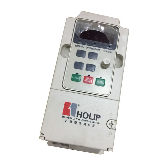
Page 24: Vi. Instruction Of The Lcp Digital Operator
HLP-NV Series VI. Instruction of the LCP Digital Operator 1. Description of the LCP Digital Operator LCP with potentiometer LCP without potentiometer 2. Programming with LCP 2.1. LCP introduction: 1. 5 numeric displays 2. 8 LEDs: FWD 、 REV 、 Hz 、 A 、 R/MIN 、 HAND 、 OFF/RESET 、 AUTO 3. - Page 25 HLP-NV Series 2.2 . General Operation The menu system allows operators to navigate through hierarchical menus which contain related menu items. The top-level menu contains two menu items: status menu 、 parameter editing menu. These two items can be explored by pressing MENU key: 2.3 .
- Page 26 HLP-NV Series The HAND, OFF/RESET and AUTO key can be disabled by changing parameter(C00.40 、 C00.41 、 C00.42). Potentiometer: used for setting the reference only. The potentiometer can be used in both hand and auto mode with different functionality: In Hand mode the potentiometer will work as the arrow keys – i.e.
- Page 27 HLP-NV Series Parameter setting example: How to set C03.17 to 21 1. Pressing MENU key to let the display go to parameter editing menu. 2. Pressing▲ ▼key to select group No.(C03.00) 3. Pressing ENTER key to edit parameter No.,then pressing▲▼key to select parameter No.
- Page 28 HLP-NV Series 2.4.2 Readout and indicator: The readout parameters toggled by pressing ENTER key: The below table shows the screen of displaying every readout parameter HLP-NV Series...
- Page 29 HLP-NV Series Warning description: when warning occurred, the LEDs of Hz 、 A will flash and R/MIN will be lit. Alarm description: when alarm occurred, the LEDs of Hz 、 A and R/MIN will f lash,and the drive will trip. A trip can be cancelled by pressing reset or, in some cases, automatically.
-
Page 30: Vii. Parameter Overview
HLP-NV Series VII. Parameter Overview Function Range&Function Default Item Fuction Description Code explanation setting [0] Resume Oper. State at Power- *[1] Forced stop, ref = C00.04 up [Hand] [2] Forced stop, ref = 0 Custom Readout Min C00.31 0.00 – 9999.00 0.00... - Page 31 HLP-NV Series Function Range&Function Default Item Fuction Description Code explanation setting Stator Leakage [Ohm] * Dep. on motor C01.33 Reactance (X1) data [Ohm] * Dep. on motor C01.35 Main Reactance (X2) data Motor Magnetisation C01.50 0 - 300 % 100% at 0 Speed Min Speed Norm.
- Page 32 HLP-NV Series Function Range&Function Default Item Fuction Description Code explanation setting C02.00 DC Hold Current 0 - 100 % C02.01 DC Brake Current 0 - 100 % C02.02 DC Braking Time 0.0 - 60.0 10.0S C02.04 DC Brake Cut In Speed 0.0 - 400.0 Hz 0.0Hz...
- Page 33 HLP-NV Series Function Range&Function Default Item Fuction Description Code explanation setting *[0] No function [1] Analog Input VIN Relative Scaling Ref. [2] Analog Input AIN C03.18 Resource [8] Pulse input 33 [11] Local bus ref [21] Lcp Potentiometer *[0] Linear C03.40 Ramp 1 Type...
- Page 34 HLP-NV Series Function Range&Function Default Item Fuction Description Code explanation setting Terminal RUN Digital C05.10 [0] No function Input [1] Reset Terminal F/R Digital [2] Coast inverse C05.11 [3] Coast and reset inv. Input [4] Quick stop inverse Terminal RST Digital [5] DC-brake inv.
- Page 35 HLP-NV Series Function Range&Function Default Item Fuction Description Code explanation setting [8] R u n o n r e f / N o warning [9] Alarm [10] Alarm or warning [12] Out of current range [13] Below current, low [14] Above current, high...
- Page 36 HLP-NV Series Function Range&Function Default Item Fuction Description Code explanation setting Ter minal EMS High C05.56 21~5000Hz 5000 Frequency Term. EMS Low Ref./ C05.57 -4999.000~4999.000 0.000 Feedb. Value Term. EMS High Ref./ C05.58 -4999.000~4999.000 50.000 Feedb. Value L i ve Z e r o Ti m e o u t C06.00...
- Page 37 HLP-NV Series Function Range&Function Default Item Fuction Description Code explanation setting Term. AIN High Ref. C06.25 -4999.000~4999.000 50.000 /Feedb. Value Ter minal AI N Filter C06.26 0.01~10.00S 0.01 Time Constant LCP potm. Low Ref C06.81 -4999.000~4999.000 0.000 ./Feedb. Value LCP potm. High Ref.
- Page 38 HLP-NV Series Function Range&Function Default Item Fuction Description Code explanation setting *[0] Digital and ControlWord C08.01 Control Site [1] Digital only [2] ControlWord only [0] None C08.02 Control Word Source *[1] FC RS485 Control Word Timeout C08.03 0.1~6500.0S 1.0S Time...
- Page 39 HLP-NV Series Function Range&Function Default Item Fuction Description Code explanation setting C08.50 Coasting Select C08.51 Quick Stop Select [0] DigitalInput C08.52 DC Brake Select [1] Bus C08.53 Start Select Comm- [2] LogicAnd unication C08.54 Reversing Select *[3] LogicOr C08.55 Set-up Select C08.56 Preset Reference Select...
- Page 40 HLP-NV Series Function Range&Function Default Item Fuction Description Code explanation setting C15.00 Operating Time 0 - 65535 C15.01 Running Hours 0~2147483647 C15.02 kWh Counter 0~65535 C15.03 Power Ups 0~2147483647 C15.04 Over Temps 0~65535 C15.05 Over Volts 0~65535 *[0] Do not reset C15.06 Reset kWh Counter...
- Page 41 HLP-NV Series Function Range&Function Default Item Fuction Description Code explanation setting C16.15 Frequency [%] -100.00~100.00% 0.00A C16.18 Motor Thermal 0~100% C16.30 DC Link Voltage 0~10000V C16.34 Heatsink Temp 0~255 ℃ C16.35 Inverter Thermal 0~100% C16.36 Inv. Nom. Current 0.01~10000.00A 0.00A C16.37 Inv.
-
Page 42: Viii. Parameter Descriptions
HLP-NV Series VIII. Parameter Descriptions 1.Parameter group 0: Operation/Display C00.04 Oper. State at Power-up (Hand) Default setting Range Resume Frequency converter starts in same Hand or Off State as when powered off. Local reference is stored and used after power-up. - Page 43 HLP-NV Series ● Connect various motors (one at a time) to frequency converter. Motor data for various motors can be placed in different set-ups. ● Rapidly change settings of frequency converter and/or motor while motor is running (eg. ramp time or preset references) via bus or digital inputs.
- Page 44 HLP-NV Series C00.40 [Hand on] Key on LCP Default setting Range Disabled Hand-on key has no function. Enabled Hand-on key is functional. C00.41 [Off / Reset] Key on LCP Default setting Range Disable Off / Reset Off /reset key has no function.
- Page 45 HLP-NV Series C01.01 Motor Control Principle Default setting Range Is used for parallel connected motors and/or special motor applications. VVC+ Normal running mode, including slip- and load compensations. ● Function: The V/F settings are set in parameters C01.55 and C01.56.
- Page 46 HLP-NV Series 0-2* Motor Data ● Function: Enter the correct motor nameplate data (power, voltage, frequency, current and speed). Run AMT, see par. C01.29. Default setting settings for advanced motor data, par. C01.3*, are automatically calculated. ● ATTENTION! Parameters in parameter group 1.2* cannot be adjusted while motor runs.
- Page 47 HLP-NV Series C01.29 Automatic Motor Tuning (AMT) Default setting Range AMT function is disabled. Enable AMT AMT function starts running. This may take up to 10 min. depending on motor power rating. ● Function : Use AMT to optimize motor performance.
- Page 48 HLP-NV Series C01.33 Stator Leakage Reactance (X1) Default setting Range Depending on motor data*[Ohm] ● Function : Set stator leakage reactance of motor. C01.35 Main Reactance (Xh) Default setting Range Depending on motor data*[Ohm] ● Function : Set motor main reactance.
- Page 49 HLP-NV Series C01.56 V/F Characteristic - F Default setting Range [0 - 400 Hz] ● Function:This parameter is an array parameter [0-5] and is only functional when par. C01.01, Motor Control Principle is set to V/F [0]. Enter f requency points to manually for m a V/ F character istic matching motor.
- Page 50 HLP-NV Series C01.61 High Speed Load Compensation Default setting 100% Range [0 - 199 %] ● Function:Use this parameter to obtain optimum load compensation when running at high speed. Enter percentage to compensate in relation to load when motor runs at high speed.
- Page 51 HLP-NV Series 1-7* Start Adjustments Considering the need for various start functions in different applications, it is possible to select a number of functions in this parameter group. C01.71 Start Delay Default setting 0.0S Range [0.0 - 10.0 s] ● Function: The start delay defines the time to pass from a start command is given until the motor starts accelerating.
- Page 52 HLP-NV Series C01.8* Stop Adjustments To meet the need for various stop functions in different application these parameters offer some special stop features for the motor. C01.80 Function at Stop Default setting Range Coast The inverter is coasted. DC hold The motor is energized with a DC current.
- Page 53 HLP-NV Series C01.90 Motor Thermal Protection Default setting Range No Protection Disables temperature monitoring. Thermistor Warning A thermistor connected to either digital or analog input gives a war ning if upper limit of motor temperature range is exceeded, (see par. C01.93, Thermistor Resource).
- Page 54 HLP-NV Series ● Function: Select the thermistor input terminal. ● ATTENTION! Analog Input VIN cannot be selected for other purposes when selected as thermistor resource. Input Digital/Analog Supply Voltage Threshold Cut-out Values Digital 10 V <800 ohm - >2.9k ohm Analog 10 V <800 ohm - >2.9k ohm...
- Page 55 HLP-NV Series C02.04 DC Brake Cut In Speed Default setting 0.0HZ Range [0.0 - 400.0 Hz] ● Function: Set DC-brake cut-in speed to activate DC braking current, set in par. C02.01, when ramping down. When set to 0 the function is off.
- Page 56 HLP-NV Series C02.17 Over-voltage Control Default setting Range Disabled The OVC is not active/required. Enabled, not at stop OVC is running unless a stop signal is active. Enabled OVC is running, also when a stop signal is active. ● Function: Use Over-voltage Control (OVC) to reduce the risk of the frequency converter tripping due to an over voltage on the DC link caused by generative power from the load.
- Page 57 HLP-NV Series Parameter group 3: Reference/Ramps Parameters for reference handling, def inition of limitations, and configuration of the frequency converter's reaction to changes 3-0* Reference Limits Parameters for setting the reference unit, limits and ranges. C03.00 Reference Range Default setting...
- Page 58 HLP-NV Series 3-1* References Parameters for setting up the reference sources. Select the preset references for the corresponding digital inputs in parameter group 5.1*, Digital Inputs. 18 Bit2 17 Bit1 16 Bit0 Preset reference no. Table 4.1: Par. C05.1* selection [16], [17] and [18] C03.10...
- Page 59 HLP-NV Series the Catch-up/Slowdown value (in %) is added to the reference function as follows: Reference = Reference + reference × Catchup Slowdown /100 Reference = Reference - reference × Catchup Slowdown /100 When the input command is inactivated, the reference returns to its original value ie.
- Page 60 HLP-NV Series C03.16 Reference Resource 2 Default setting Range No Function No reference signal is defined. Analog Input VIN Use signals from analog Input VIN as reference. Analog Input AIN Use signals from analog Input AIN as reference. [11] Local Bus Ref.
- Page 61 HLP-NV Series C03.18 Relative Scaling Ref. Resource Default setting Range No Function The function is disabled Analog Input VIN Select analog Input VIN as relative scaling reference source. Analog Input 54 Select analog input 54 as relative scaling reference source.
- Page 62 HLP-NV Series Ramp Times: Ramp up: Acceleration time. From 0 to nominal motor frequency (par. C01.23). Ramp down: Deceleration time. From nominal motor frequency (par. C01.23) to 0. Limitation: Too short ramp up time can result in Torque limit warning (W12) and/or DC over voltage warning (W7).
- Page 63 HLP-NV Series C03.5* Ramp2 See par. C03.4* for a description of ramp types. ATTENTION! Ramp2 - alternative ramp times: Changing from Ramp1 to Ramp2 is done via the digital input. See par. C05.1*, selection[34]. C03.50 Ramp 2 Type Default setting...
- Page 64 HLP-NV Series C03.81 Quick Stop Ramp Time Default setting 3.00/ 30.00S* Range [0.05 - 3600 s] ● Function: A linear ramp applicable when Q-stop is activated. See par. C05.1*, selection [4]. * only for NV4,NV5 Parameter group 4: Motor Limits Parameter group for configuring limits and warning.
- Page 65 HLP-NV Series C04.14 Motor Speed High Limit [Hz] Default setting 65.0HZ Range [0.0 - 400.0 Hz] ● Function: Set the Maximum Motor Speed corresponding to the maximum output frequency of the motor shaft. ● ATTENTION! As the maximum output frequency is an absolute value, it cannot be deviated from.
- Page 66 HLP-NV Series ● Function: A missing motor phase causes the motor torque to drop. This monitor may be disabled for special purposes (eg. small motors running pure V/F mode), but as there is a risk of overheating the motor, Danfoss strongly recommends that the function is On.
- Page 67 HLP-NV Series C05.10 Terminal RUN Digital Input Default setting C05.11 Terminal F/R Digital Input Default setting C05.12 Terminal RST Digital Input Default setting C05.13 Terminal JOG Digital Input Default setting C05.15 Terminal EMS Digital Input Default setting Range See the following table...
- Page 68 HLP-NV Series changes direction of rotation; it does not activate star t function. Select Both directions [2] in par. 4.10. 0 = normal, 1 = reversing. [11] Start reversing Use for start/stop and for reversing at the same time. Signals on start [8] are not allowed at the same time.
- Page 69 HLP-NV Series [21] Speed up Select Speed up and Speed down if digital control of the up/down speed is desi red (motor potent iometer). Activate this function by selecting either Freeze reference or Freeze output. When Speed up is activated for less than 400 ms. the resulting reference will be increased by 0.1%.
- Page 70 HLP-NV Series [0] No Operation D ef a u lt fo r a l l d ig it a l a n d r el ay outputs. [1] Control Ready Control board receives supply voltage. [2] Drive Ready Frequency conver ter is ready for operation and applies supply signal on control board.
- Page 71 HLP-NV Series specified voltage range. [25] Reverse Motor runs/is ready to run clockwise when logic = 0 and counter clockwise when logic = 1. Output changes as soon as reversing signal is applied. [26] Bus OK Active communication (no time-out) via serial communication port.
- Page 72 HLP-NV Series C05.57 Term. EMS Low Ref./Feedb. Value Default setting 0.000 Range [-4999.000 -4999.000] ● Function: Set reference/feedback value corresponding to low pulse frequency value set in par. C05.55. C05.58 Term. EMS High Ref./Feedb. Value Default setting 50.000 Range [-4999.000 -4999.000] ●...
- Page 73 HLP-NV Series C06.01 Live Zero Timeout Function Default setting Range Function is disabled. Freeze output Output frequency remains at value it had when live zero was detected. Stop F r e q u e n c y c o n v e r t e r r a m p s down to 0 Hz.
- Page 74 HLP-NV Series C06.10 Terminal VIN Low Voltage Default setting 0.07V Range [0.00 - 9.99V] Enter low voltage value. ● Function: This scaling value should correspond to minimum reference value set in par. C06.14. See also section Reference Handling. C06.11 Terminal VIN High Voltage Default setting 10.00V...
- Page 75 HLP-NV Series C06.16 Terminal VIN Filter Time Constant Default setting 0.01s Range [0.01 - 10.00 s] Enter time constant. ● Function: A first-order digital low pass filter time constant for suppressing electrical noise in Terminal VIN. A high time constant value improves dampening but also increases time delay through the filter.
- Page 76 HLP-NV Series C06.26 Terminal AIN Filter Time Constant Default setting 0.01s Range [0.01 - 10.00 s] Enter time constant. ● Function: A first-order digital low pass filter time constant for suppressing electrical noise in terminal 54. A high time constant value improves dampening, but also increases time delay through the filter.
- Page 77 HLP-NV Series C06.91 Terminal AON Analog Output Default setting Range No Operation [10] Output Frequency [11] Reference [12] Feedback [13] Motor Current [16] Power [20] Speed ● Function: Select the function for Terminal AON as an analog output. C06.92 Terminal AON Digital Output...
- Page 78 HLP-NV Series Parameter group 7: Controllers Parameters group for configuring application controls. C07.2* Process Ctrl. Feedb Select feedback sources and handling for Process PI Control. C07.20 Process CL Feedback 1 Resource Default setting Range No Function Analog Input VIN Analog Input AIN...
- Page 79 HLP-NV Series C07.31 Process PI Anti Windup Default setting Range Disable Regulation of a given error will continue even when the output f requency can not be increased / decreased. Enable P I - c o n t r o l l e r c e a s e s f r o m...
- Page 80 HLP-NV Series Parameter group 8: Communication Parameter group for configuring communication. 8-0* General Settings Use this parameter group for configuring the general settings for communication. C08.01 Control Site Default setting Range Digital and Control Word Use both digital input and control word as control.
- Page 81 HLP-NV Series C08.04 Control Word Timeout Function Default setting Range No function. Freeze Output Freeze output until communication resumes. Stop S t o p w i t h a u t o r e s t a r t w h e n communication resumes.
- Page 82 HLP-NV Series C08.31 Address Default setting Range [1 - 126] ● Function: Select the address for the bus. FC -bus range is 1-126. Modbus range is 1-247. C08.32 FC Port Baud Rate Default setting Range 2400 Baud 4800 Baud 9600 Baud...
- Page 83 HLP-NV Series 8-5* Digital/Bus Parameters for configuring control word Digital/Bus merging. ATTENTION! Parameters are only active when par. C08.01, Control SIte, is set to Digital and control word [0]. C08.50 Coasting Select Default setting Range Digital Input Activation via a digital input.
- Page 84 HLP-NV Series C08.53 Start Select Default setting Range Digital Input Activation via a digital input. Activation via serial communication port. LogicAnd Activation via serial communication port and a digital input. LogicOr Activation via serial communication port or a digital input.
- Page 85 HLP-NV Series C08.56 Preset Reference Select Default setting Range Digital Input Activation via a digital input. Activation via serial communication port. LogicAnd Activation via serial communication port and a digital input. LogicOr Activation via serial communication port or a digital input.
- Page 86 HLP-NV Series ● Function: This feature allows more accurate speed control near and over nom i nal speed (50/60 H z). A nother advant age with overmodulation is the ability of staying at a constant speed even though mains is dropping.
- Page 87 HLP-NV Series ● Function: Select reset function after tripping. Once reset, frequency converter can be restarted. ● warning: Motor may start without warning. C14.21 Automatic Restart Time Default setting Range [0 - 600 s] ● Function: Enter time interval from trip to start of automatic reset function.
- Page 88 HLP-NV Series Parameter group 15: Drive Information Parameter group containing information on operating data, hardware configuration, software version, etc. 15-0* Operating Data Parameter group containing operating data e.g. Operating Hours, kWh counters, Power Ups, etc. C15.00 Operating Time Default setting...
- Page 89 HLP-NV Series C15.05 Over Volts Default setting Range [0 - 65535] ● Function: View number of times frequency converter has tripped due to over voltage. Counter cannot be reset. C15.06 Reset kWh Counter Default setting Range Do Not Reset Counter is not reset.
- Page 90 HLP-NV Series C15.43 Software Version Default setting View software version of frequency converter. C15.46 Frequency Converter Order. No Default setting View ordering number for re-ordering frequency converter in its original configuration. C15.48 LCP ID No Default setting View LCP ID number.
- Page 91 HLP-NV Series C16.03 Status Word Default setting Range [0 - 65535] ● Function: View status word sent to frequency converter via serial communication port. C16.05 Main Actual Value [%] Default setting 0.00 Range [-100.00 - 100.00%] ● Function: View two-byte word sent with status word to bus Master reporting main actual value.
- Page 92 HLP-NV Series C16.18 Motor Thermal Default setting Range [0 - 100%] ● Function: View calculated thermal motor load as percentage of estimated thermal motor load. 16-3* Drive Status Parameters for reporting the status of the frequency converter. C16.30 DC Link Voltage...
- Page 93 HLP-NV Series C16.52 Feedback [Unit] Default setting 0.000 Range [-4999.000 -4999.000] ● Function: View analog or pulse feedback in Hz. 16-6* Inputs and Outputs Parameters for reporting the digital and analog IO ports. C16.60 Digital Input RUN,F/R,RST,EMS Default setting Range [0 - 1111] ●...
- Page 94 HLP-NV Series C16.72 Counter A Default setting Range [-2147483648 -2147483647] ● Function: View present value of Counter A. C16.73 Counter B Default setting Range [-2147483648 -2147483647] ● Function: View present value of Counter B. 16-8* FC Port Parameter for viewing references from FC Port.
-
Page 95: Precautions About Inspection And Maintenance
HLP-NV Series X . M a i n t e n a n c e , F a u l t I n f o r m a t i o n a n d Troubleshooting Periodical maintenances and inspections will keep your inverter in its normal state for long time. -
Page 96: Fault Indication And Troubleshooting
● Please make periodical cleaning of vent holes. 3. Fault Indication and Troubleshooting The inverter of HLP-NV series is relatively perfective with the protection functions of overload, inter-phase short circuit, earth short circuit, under- voltage, overheating and over-current, etc. When a protection function happens with the inverter please check the reasons of faults according to the information listed in the table below. -
Page 97: Fault Code Description And Analysis
HLP-NV Series 4. Fault code description and Analysis Fault Contents Fault Display Disposal methods & Description Signal on terminal VIN or AIN is less Live zero than 50% of value set in par. C6.10, error C6.12 and C6.22 Missing phase on supply side, or too Mains phase high voltage imbalance. - Page 98 HLP-NV Series Fault Contents Fault Display Disposal methods & Description Over Current Inverter peak current limit is exceeded. D i s ch a rge f r om out put ph a s e s t o Earth fault ground. Shor t-circuit in motor or on motor Short Circuit terminals.
- Page 99 Motor phase V is missing. Check the V missing phase. Motor phase Motor phaseW is missing. Check the W missing phase. Internal fault Contact local HOLIP supplier. 24 V supply Exter nal 24 V DC back-up power supply may be overloaded. HLP-NV Series...
- Page 100 HLP-NV Series Fault Contents Fault Display Disposal methods & Description AMT check Wrong setting for motor voltage and/or Unom and motor current. Inom AMT low Mo t o r c u r r e n t i s t o o low. C h e ck Inom settings.
- Page 101 HLP-NV Series IX. Appendices Appendix 1: Mounting Dimensions of HOLIP NV inverters 1) Mechanical drawing Inverter Model ppearance and Installation Dimensions HLPNV0D1821A HLPNV0D3721A HLPNV0D7521A HLPNV01D521A HLPNV02D221A HLPNV0D2523A HLPNV0D3723A HLPNV0D7523A HLPNV01D523A HLPNV02D223A HLPNV03D723A HLPNV0D3743A HLPNV0D7543A HLPNV01D543A HLPNV02D243A HLPNV03D043A HLPNV04D043A HLPNV05D543A HLPNV07D543A...
- Page 102 HLP-NV Series 2):External Dimensions Table (Unit: mm) Frame Model HLPNV0D1821A HLPNV0D2523A HLPNV0D3721A HLPNV0D3723A Φ4.5 Φ4.5 HLPNV0D3743A HLPNV0D7521A HLPNV0D7523A HLPNV0D7543A HLPNV01D521A HLPNV01D523A Φ4.5 Φ4.5 HLPNV01D543A HLPNV02D243A HLPNV02D221A HLPNV02D223A HLPNV03D043A HLPNV03D723A Φ4.5 Φ4.5 HLPNV04D043A HLPNV05D543A HLPNV07D543A HLPNV001143A Φ7 Φ7 HLPNV001543A HLPNV18D543A Φ7 Φ7...
- Page 103 HLP-NV Series Appendix 2: Mounting Dimensions of LCP Digital operator Inverter Appearance and Installation Dimensions(Unit:mm) Model HOLIP-NV operator Appendix 3. Braking Resistor Disposition 200-240V Braking resistor Model Braking torque Suitable Specification (KW) 40%ED Motor(KW) Ω 380-440V Braking resistor Model Braking torque...
- Page 104 HLP-NV Series Appendix 4. Simple Example of Appliaction 1 : Parameter Initialization C14.22 used to reset parameter to default settings • Set C14.22 = 2 • Hold down“ENTER”to confirm changing • Cut off mains • Resart the drive 。 E80 was displayed to indicate the completion of the process •...
- Page 105 HLP-NV Series Use terminals of RST and EMS to realize: C05.11 = 19 C05.10 = 8 C05.12 = 21 C05.13 = 22 Press "Auto" key to active Auto mode 6: Multi-speed ( eight speed at most ) Use terminals of RST,JOG,EMS to select preset reference C05.10 = 8(Start)
- Page 106 HLP-NV Series Speed select table ( 0 : OFF 1 : ON ) Speed Speed 1 Speed 2 Speed 3 Speed 4 Speed 5 Speed 6 Speed 7 Speed 8 7: Process close loop control ( PI control ) C01.00 = 3 setpoint: C03.15, C03.16, C03.17, C03.14, C03.18 defines the setpoint of PI...
- Page 107 HLP-NV Series 8: Pulse input C03.15 = 8 Pulse input select C03.16 = 0 C03.17 = 0 C05.10 = 8 Start command C05.15 = 32 Pulse input select C05.55 = 20 Terminal EMS low frequency C05.56 = 5000 Terminal EMS high frequency C05.57 = 0...
- Page 108 HLP-NV Series Press "Auto"to active Auto mode Connect RUN with EV to operate the drive. Connect F/R with EV to operate the drive 10:V/F and VVC+ 1: V/F C01.01 = 0 V/F principle C01.55 (0) (1) (2) (3) (4) (5) -- Voltage setting of V/F characteristic 10 55 380 380 380 380 C01.56 (0) (1) (2) (3) (4) (5) -- Voltage setting of V/F characteristic...
- Page 109 HLP-NV Series mode (LCP: OP-VB03) C3.00 = 1 Press "Hand"”to active hand mode Press “ ∧ ” key , reference increase to maximum reference Press “ ∨ ” key , referencedecrease to -maximum reference 14:Communication examples FC-protocol C08.32 = 9600bps C08.33 = 0 14.1 Start with the reference of 50HZ Send:...
- Page 110 HLP-NV Series TX: 01 01 0010 0010 3C03 RX: 01 01 333C AD1D 3C33 means 47.03Hz Read status word: (47.03Hz Run) TX: 01 01 0020 0010 3C0C RX: 01 01 02 070D 7A09 12.6: Read holding registers ---Read the value of parameters Read C03.41 Address: 341*10 –1=3409=0D51H...
- Page 111 HLP-NV Series Appendix 5:User’s feedback Function Fuction Default User’s Item Code Description setting Par. C00.04 Oper. State at Power-up [Hand] C00.31 Custom Readout Min Scale 0.00 C00.32 Custom Readout Max Scale 100.00 Operation C00.40 [Hand on] Key on LCP / Display C00.41 [Off / Reset] Key on LCP...
- Page 112 HLP-NV Series Function Fuction Default User’s Item Code Description setting Par. C02.00 DC Hold Current C02.01 DC Brake Current C02.02 DC Braking Time 10.0S C02.04 DC Brake Cut In Speed 0.0Hz C02.10 Brake Function Brakes C02.11 Brake Resistor (ohm) 5Ω...
- Page 113 HLP-NV Series Function Fuction Default User’s Item Code Description setting Par. C05.10 Terminal RUN Digital Input C05.11 Terminal F/R Digital Input C05.12 Terminal RST Digital Input C05.13 Terminal JOG Digital Input C05.15 Terminal EMS Digital Input Digital C05.40 Function Relay In / Out C05.55 Terminal EMS Low Frequency...
- Page 114 HLP-NV Series Function Fuction Default User’s Item Code Description setting Par. C06.92 Terminal AO Digital Output C06.93 Terminal AO Output Min Scale 0.00% C06.94 Terminal AO Output Max Scale 100.00% C07.20 Process CL Feedback 1 Resource C07.30 Process PI Normal/ Inverse Ctrl C07.31 Process PI Anti Windup...
- Page 115 HLP-NV Series Function Fuction Default User’s Item Code Description setting Par. C15.00 Operating Time C15.01 Running Hours C15.02 kWh Counter C15.03 Power Ups C15.04 Over Temps C15.05 Over Volts C15.06 Reset kWh Counter C15.07 Reset Running Hours Counter Drive Information C15.30 Fault Log: Error Code...
- Page 116 HLP-NV Series Function Fuction Default User’s Item Code Description setting Par. Digital Input RUN,F/ C16.60 R,RST,EMS C16.61 Digital Input JOG C16.62 Analog Input VIN (volt) 0.00 C16.63 Analog Input VIN (current) 0.00 C16.64 Analog Input AIN 0.00 C16.65 Analog Output AO [mA] 0.00...
Need help?
Do you have a question about the HLP-NV Series and is the answer not in the manual?
Questions and answers
Сброс на заводские настройки Сброс на заводские настройки