
Related Manuals for REL Acoustics No. 25


Summary of Contents for REL Acoustics No. 25
- Page 2 Operating Instructions for the No.25 Sub-Bass System...
- Page 3 Caution Marking Explanation The lightning flash with arrowhead symbol within an equilateral triangle is intended to alert the user to the presence of un-insulated dangerous voltage within the product’s enclosure that may be of sufficient magnitude to constitute a risk of electric shock to persons. The exclamation point within an equilateral triangle is intended to alert the user to the presence of important operating and maintenance (servicing) instructions in the literature accompanying the appliance.
-
Page 4: Important Safety Instructions
Important Safety Instructions 1 Read all of these instructions. 2 Save these instructions for future use. 3 Heed all warnings. 4 Follow all instructions. 5 Do not use this apparatus near water. 6 Clean only with automotive polish and micro fiber cloth. 7 Install in accordance with the manufacturer’s instructions. - Page 5 Warning To reduce the risk of fire or electric shock, do not expose this apparatus to rain or moisture. The apparatus shall not be exposed to dripping or splashing and no objects filled with liquids, such as vases, shall be placed on apparatus. The mains plus is used as disconnect device.
- Page 6 Attention Explication Marquage L’éclair avec le symbole de pointe de flèche dans un triangle équilatéral est destiné à alerter l’ utilisateur de la présence de non isolée tension dangereuse à l’intérieur de l’enceinte du produit qui peut être d’une ampleur suffisante pour constituer un risque d’électrocution pour les personnes.
- Page 7 Informations Importantes Relatives a la Securite 1 Lisez attentivement ces instructions. 2 Conservez ces instructions. 3 Respectez tous les avertissements. 4 Suivez toutes les instructions. 5 Ne pas utiliser cet appareil près de l’eau. 6 Nettoyez seulement avec du vernis automobile et tissu microfibre. 7 Installer conformément aux instructions du fabricant.
- Page 8 Avertissement Cet article est lourd. Pour éviter tout risque de blessure, prendre soin lors de la manipulation. L’ appareil ne doit pas être exposé à des éclaboussures et aucun objet rempli de liquide, comme des vases, ne doit être placé sur l’appareil. Les conduites Plus est utilisé...
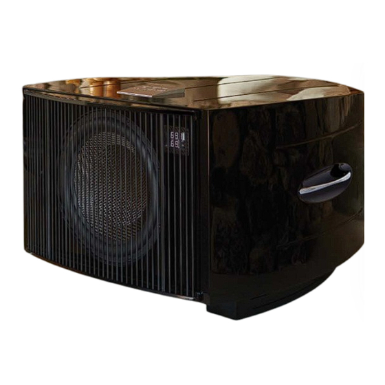
- Page 9 Dear No.25 Owner Thank you for purchasing your new REL No.25, this unit is produced with great pride and operates as the standard bearer summarizing a journey that has taken REL 25 years to achieve. As the commemorative unit marking 25 successful years, the No.25 takes all the best technologies developed over the past quarter century and adds a few important design improvements to create a new standard to carry us on to the next 25 years.
- Page 10 smooth out the overall in-room response. While it takes a little practice (and generally a gentle hand on the controls is highly recommended) the results are highly gratifying. Use it to gently fill in an area that requires more output and then gently cut bass in the upper range that is too exuberant. A Beautiful Body: The curvaceous cabinet is designed to push further the experience of minimizing internal cabinet resonances by creating a curvilinear cabinet that does not permit any single frequency from building up a dominant mode.
- Page 11 REL No.25 Remote Control and Rear Panel Legends Remote Control Crossover: Used to adjust crossover frequency. Variable between 20-90Hz. .1/LFE Level: Used to adjust output level when using .1/LFE input from a surround-sound processor. Also used to adjust Parametric EQ frequency. High/Low Level: Volume control for High/Low Input.
- Page 12 REL No.25 Rear Panel Connection Legend .1/LFE RCA Input: Used to connect to the .1/LFE output of a surround-sound processor. .1/LFE RCA Output: Used to connect or “daisy chain” another REL No.25 in tandem. Left & Right Channel Low-Level RCA Input: Used to connect low-level signals to the sub-bass system from the output of a preamplifier, integrated amplifier or receiver.
- Page 14 Connectivity and Functionality High-Level Input Connections should be made to the same binding post on main amplifier as the main speakers. Red to amplifier main right speaker red terminal, yellow to amplifier main left speaker red terminal and black to amplifier main speaker black terminal, right or left but not both.
- Page 15 filter 2, and the Hi/Lo Level control on the remote changes the level of EQ filter 2. Each filter has a frequency range from 20Hz to 90Hz. The level set of each filter is +/- 6 dB in 1/3 dB increments. LED Display An LED display is located on the upper right front of No.25.
- Page 16 Connecting Up Always switch off your system before disconnecting any wires. To increase the versatility of connecting up, the No.25 models have three separate inputs. A high-level input socket, a .1/LFE input consisting of both RCA and XLR connectors, and a low-level input that includes two RCA sockets for stereo input.
- Page 17 REL Set-Up Made Simple REL products are not traditional subwoofers, but true Sub-Bass Systems. A REL is designed to augment the performance of “full range” speaker systems in order to provide, in certain cases, linear response below 15Hz. Therefore, for the moment, please set aside everything you’ve been taught about subwoofers and how they are integrated into a stereo or home cinema system.
- Page 18 • The standard high-level hook up procedure is: attach the red wire to the amplifier’s right positive speaker output terminal; attach the yellow wire to the amplifier’s left positive speaker output terminal; attach the black wire to whichever of the amplifier’s ground output terminals is convenient; plug the Speakon® connector into the Sub-Bass System’s high-level input.
- Page 19 and connecting the REL’s ground will produce an undesirable shorting to ground. If connecting to a Class-D amplifier, follow the above connection procedure for differential amplifiers. • When connecting RELs to Mono Bloc amplifiers (2) RELs, one for each amplifier, must be used. Connect the black wire of each REL to the negative speaker terminal of the corresponding amplifier channel;...
- Page 20 • If connecting a single REL as a dedicated centre channel sub, an insider tip is to consider connecting to the rear of the speaker, rather than routing the REL High Level enable all the way back to the amplifier. Connect the black wire of the REL to the negative centre channel speaker terminal;...
- Page 21 When connecting to a home cinema system where there is a .1/LFE channel output, connect a single RCA to RCA or XLR to XLR cable between the sub output of the processor/receiver and the .1/LFE input jacks on the REL. Positioning: The optimal position for a single REL No.25 is in one of the corners behind the main speakers.
- Page 22 Corner Fine Tuning: (When Setting up for Stereo No.25 it is Possible that Placement is Not Corner Loaded and this Step May be Omitted). The next step is to determine precisely how far from the corner the sub should be placed to achieve the most efficient output, as well as the lowest frequency extension. With the REL fully into the corner, and pointing straight out along the diagonal coming out of the corner, continuing to play the music, slowly pull the REL from the corner on the diagonal, equidistant from both side and rear wall.
- Page 23 Parametric Equalizers It is not recommended that average users attempt to use the parametric equalizers included in No.25 as miss-application of these filters can produce results detrimental to the average room. No.25 provides for 2 parametric filters that may be used to cure certain room acoustics challenges. Use of these should very much be seen as optional, and engaging either requires physically turning on the toggle switch on the rear panel that supplies power to BOTH parametric EQ’s.
- Page 24 Set-Up: When setting up stereo No.25s, it is possible to place both units in the front corners of the room, carefully toed-in and placed per normal guidance in this manual. Connect each sub to the speaker terminal outputs based on the following diagrams for standard stereo amp, non-balanced mono blocks or balanced differential mono blocks.
- Page 25 Expert Set-Up: Preferable is to bring the subs further out into the room and place them slightly behind and outboard of the main speakers. 1 Set each side up independently. Disconnect the sub that is not being set-up so your complete focus can be given over to the sub that is being set-up.
- Page 26 3 Once each sub has been carefully tuned, attach the cables for both subs. At this point, the output achieved will be too loud and will require re-setting the volume/gain control of each No.25 lower. This is normal as the combined output is likely to be at least 3 db louder with both subs now being used. Using the supplied remote, carefully turn down each sub until perfect balance is achieved.
- Page 27 Stacking Kit The kit contains instructions for stacking, as well as a Speakon-to-Speakon high-level jumper cable for daisy-chaining. Theatre Applications For Dolby Digital AC3 or other 5.1 theatre systems, once the standard set-up for two-channel outlined above is complete, the LFE output from the processor or receiver should be connected to the .1/LFE INPUT and appropriate volume adjustments made using the .1/LFE level control.
- Page 28 Technical No.25 employs an advanced filter circuit which provides exceptional performance when coupled to the rest of the signal chain of the Sub-Bass System. A second-order variable low-pass filter approximating a Bessel function was chosen for its linear phase response, which equates to flat group delay. This means that, unlike other filter functions, the amount of delay the signal is subjected to during processing is constant through the entire pass-band, which improves the frequency response and allows for better integration of the sub with the main speakers.
- Page 29 A thermal overload device is fitted to all No.25 Sub-Bass Systems. If the unit is deliberately over-driven this device will sense the temperature rise and cut the output; recovery time is approximately five minutes. If this happens, it is a warning that the unit is being over-driven and the volume level control should be reduced to a safe level.
- Page 30 The REL No.25 is shipped in the “ALWAYS ON” mode with the wireless receiver disabled. During initial setup, use the REL this way. If you are using a REL Longbow™ transmitter for initial setup, the wireless switch must be enabled, please follow instructions for pairing included in the REL Longbow™ transmitter manual.
- Page 31 After initial setup, if you wish to employ the standby mode, simply move the power mode switch into the up position to “STANDBY”. Power Draw Model Standby Standby w/ wireless Idle No.25 > 0.5 Watts > 1 Watt 40 Watts...
- Page 32 Supplied Accessories Mains Lead: Neutrik Speakon Interconnect: Yes (10 Meters Nominal) Users Manual: Remote Control: Batteries (AAA x 2): Allen Key (2.5mm): In the interest of product development, REL Acoustics Limited reserve the right to vary these specifications without notice...
- Page 33 REL Acoustics Limited North Road, Bridgend industrial Estate . Bridgend, CF31 3TP . United Kingdom Telephone: +44 (0)1 656 768 777 . Fax: +44 (0) 1 656 766 093 Web: www.rel.net...
Need help?
Do you have a question about the No. 25 and is the answer not in the manual?
Questions and answers