
Related Manuals for JRC JHS-183


Summary of Contents for JRC JHS-183
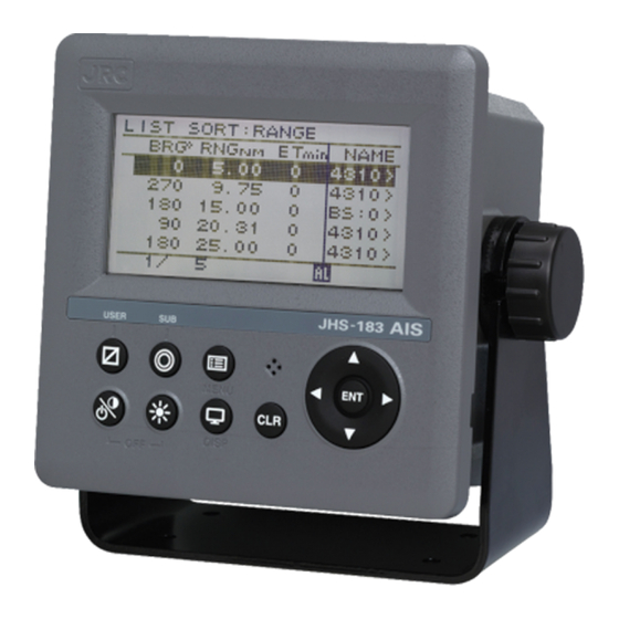
- Page 1 JHS-183 JHS-183 Automatic Identification System Automatic Identification System INSTRUCTION INSTRUCTION MANUAL MANUAL...
- Page 3 Thank you for purchasing the JHS-183 Automatic Identification System (AIS). The JHS-183 is a Class A shipborne AIS equipment that communicates ship's static data and ship's dynamic data with other vessels or coast stations on VHF channels using TDMA techniques.
-
Page 4: Before Operation
Before Operation Concerning the symbols This manual uses the following symbols to explain correct operation and to prevent injury or damage to property. The symbols and descriptions are as follows. Understand them before proceeding with this manual. WARNING Indicates a warning that, if ignored, may result in serious injury or even death. -
Page 5: Handling Precautions
Handling Precautions WARNING Do not disassemble or customize this unit. Doing so may cause fire, electrical shock or malfunction. Do not use a voltage other than specified. Doing so may cause fire, electrical shock or malfunction. Do not attempt to check or repair the interior of this equipment by non-qualified service personnel, as doing so may cause fire, electric shock or malfunction. - Page 6 CAUTION Do not use this equipment for anything other than specified. Doing so may cause malfunction or damage to persons. Do not adjust the trimmer resistors or the trimmer capacitors on the PCB unit, except when and if they need to be adjusted. Doing so may cause malfunction or damage to persons.
-
Page 7: External Views
External Views NTE-183 AIS Transponder NCM-983 AIS Controller... - Page 8 ・Optional equipment NQE-5183 Connection Box NBD-577C Power Supply Unit...
-
Page 9: Table Of Contents
CONTENTS Preface ....................... ⅰ Before Operation ....................ⅱ Handling Precautions ..................ⅲ External Views ....................ⅴ 1. GENERAL ..................... 1-1 1.1 Outlines ....................... 1-1 1.2 Features ...................... 1-1 1.3 Components ....................1-2 1.3.1 Standard Components ................1-2 1.3.2 Options ....................1-2 1.3.3 Configuration .................... - Page 10 5.3.2.4 Interrogation ..................5-33 5.3.2.5 Long Range Messages ................. 5-35 5.3.3 Maintenance .................... 5-37 5.3.3.1 Self Diagnosis ..................5-38 5.3.3.2 Communication Test ................5-41 5.3.3.3 AIS Alarm ....................5-42 5.3.3.4 Sensor Status ..................5-44 5.3.3.5 Event Log....................5-45 5.3.3.6 Software Version ................... 5-45 5.3.4 Set up Menu ....................
- Page 11 8. SPECIFICATIONS ..................8-1 8.1 General (JHS-183) ..................8-1 8.2 AIS Transponder (NTE-183) ............... 8-1 8.2.1 TRX port ....................8-1 8.2.2 Environmental condition ................8-1 8.3 AIS Controller (NCM-983) ................8-2 8.3.1 Operation panel ..................8-2 8.3.2 Environmental condition ................8-2 8.3.3 External interfaces ...................
-
Page 13: General
● Increased Probability of Vessel Detection ━━━━━━━━━━━━━━━━━━━━━━━━━━━━━━━━━━━━━━━━━━━ JHS-183 is equipped with a guard zone alert function. When preset guard zone range and other vessel enters into the zone, JHS-183 indicates and sounds the alert. This function enhances probability of vessel detection. -
Page 14: Components
Components 1. 3. 1 Standard Components Description Model Notes With 1 whip antenna, 2 fitting bands AIS Transponder NTE-183 1 connector N-P-10U 2 Rubbers 10 x 10 x 10 AIS Controller NCM-983 With 4 tapping screws Spare parts 7ZXJD0136 Instruction manual 7ZPJD0553A English 1. -
Page 15: Configuration
1. 3. 3 Configuration • System Block Diagram NTE-183 AIS TRANSPONDER NQE-5183 AIS CONNECTION BOX (OPTION) NBD-577C POWER SUPPLY (OPTION) NCM-983 AIS CONTROLLER +24VDC 110/220VAC... -
Page 16: Outline
Outline • Outline Drawing of NTE-183 AIS Transponder Unit: mm Mass: approx. 2.6kg... - Page 17 • Outline Drawing of NCM-983 AIS Controller ━━━━━━━━━━━━━━━━━━━━━━━━━━━━━━━━━━━━━━━━━━━ Unit: mm Mass: approx. 2.1 kg...
- Page 18 • Outline Drawing of NQE-5183 Connection Box ━━━━━━━━━━━━━━━━━━━━━━━━━━━━━━━━━━━━━━━━━━━ Unit: mm Mass: approx. 2.5 kg...
- Page 19 • Outline Drawing of NBD-577C Power Supply Unit ━━━━━━━━━━━━━━━━━━━━━━━━━━━━━━━━━━━━━━━━━━━ Unit: mm Mass: approx. 5.2 kg...
- Page 20 • Outline Drawing of NQE-3150 Pilot Plug Box ━━━━━━━━━━━━━━━━━━━━━━━━━━━━━━━━━━━━━━━━━━━ Unit: mm Mass: approx 0.36kg • Outline Drawing of NBG-380 Power Supply Unit for Personal Pilot Unit ━━━━━━━━━━━━━━━━━━━━━━━━━━━━━━━━━━━━━━━━━━━ Unit: mm Mass: approx 6.5kg...
-
Page 21: Installation Diagram
2. INSTALLATION DIAGRAM Notes: Leave installation of this equipment to our service center or agents. Installation by an unauthorized person may results in malfunction. -
Page 23: Part Names And Functions
3. PART NAMES AND FUNCTIONS NCM-983 AIS Controller ① ⑧ ⑨ ③ ④ ⑩ ⑪ ⑤ ⑦ Buzzer ② ⑥ ① LCD Display For further information, refer to “4 DISPLAYS on page 4-1”. ② MENU key Displays the Main-menu. ③ Up, Down, Right, Left key Moves the cursor, scrolls the display screen, and selects the item. - Page 24 ⑱ ⑯ ⑰ ⑭ ⑮ ⑫ ⑬ ⑫ POWER/DATA1 connector Connect to power supply, sensor and external equipment by using controller cable or connect to connection box (option). ⑬ AIS transponder connector Connect to AIS transponder by a coaxial cable. ⑭...
-
Page 25: Displays
4. DISPLAYS Operation indicator Indicates the equipment condition. When these 4 squares are flashing in order, it means normal condition. The display order of other ships Indicates the order displayed at the LIST SORT screen. Screen Title Indicates the screen’s content Guard mark indication When other ships enter the guard zone, this mark is displayed and alarm buzzer sounds. -
Page 27: Operation
5. OPERATION 5.1 Menu Tree POSN/Date [DISP] Own ship's TRX conditi on [DISP] Own ship's detail2 [DISP] Own ship's detail1 [DISP] Graphic display [SUB] 1. Range 2. Bearing 3. Sort 4. Name 5 .Guard zone 6. Number of ships 7. Contrast [DISP] 8. -
Page 28: Basic Operation
5.2 Basic Operation 5.2.1 Turning ON the power Holding down the PWR/CONT key for 1 second turns on the power, the starting screen appears about 2 seconds later, and then the Other Ships List display appears about 10 seconds later. Caution Check the main power supply of the switchboard and a cable connection of NCM-983 AIS controller when the power cannot be turned on. - Page 29 a) The voyage static data mismatch When only voyage data is different, it is displayed as follows. When [OK] is selected, voyage static data setting screen is displayed. When [CANCEL] is selected, LIST SORT screen is displayed. Confirms the voyage data and select [ENT]. Refer to 5.3.1 VOYAGE DATA SETTING for the change of the setting and the operating method.
-
Page 30: Other Ships List
5.2.1.1 Other Ships List After turning on the power, “LIST SORT” screen for other ships list appears. If “MAIN MENU” screen is displayed, press CLR key and “LIST SORT” screen is appeared. L I S T S O R T : R A N G E ▲: Ability to scroll B R G °... -
Page 31: Other Ship's Detail Information
MF ID: Manufacture code (factory code) ▼ 7 / 9 MODEL CODE: Model information (e.g. AIS JHS-183, MF ID:JRC、MODEL CODE:3) O T H E R S H I P ' S D E T A I L C A R G O / S T A T U S ▲... -
Page 32: Own Ship's Detail Information
5.2.1.3 Own Ship’s Detail Information Press DISP key at “GRAPHIC” display screen and then “OWN SHIP’S DETAIL” screen is displayed. Own ship’s information consist of 2 kinds of own ship’s detail information screens and own ship’s TRX information screen. When DISP key is pressed, each screen is switched according to the following flow: ●... - Page 33 Contents for “OWN SHIP’S DETAIL 1” information screen are shown below. Static information of own ship is mainly displayed. To see the next page/the previous page, press “▲”key or “▼“key. O W N S H I P ' S D E T A I L 1 M M S I : 4 3 1 1 0 0 0 0 1 N A M E...
- Page 34 Contents for “OWN SHIP’S DETAIL 2” information screen are shown below. Dynamic information of own ship is mainly displayed. O W N S H I P ' S D E T A I L 2 To see the next page/the previous page, P O S N D E V I C E press “▲”key or “▼“key.
- Page 35 Contents for “OWN SHIP’S TRX” information screen are shown below. Own ship radio information is mainly displayed. O W N S H I P ' S T R X : 2 0 8 7 To see the next page/the previous page, : 2 0 8 8 press “▲”key or “▼“key.
-
Page 36: Display Setup Of Other Ships List
5.2.1.4 Display Setup of Other Ships List In order to change the display setting of other ship list, press SUB key at “LIST SORT” screen for other ships list and switch to SUB screen. L I S T S O R T : R A N G E L I S T D I S P . -
Page 37: Graphic Display
5.2.1.5 Graphic Display In order to switch from “LIST SORT” screen for other ships list to “GRAPHIC” display screen, press DISP key. (Refer to 5.2.1.3 for DISP key operation) (Refer to 5.4 Graphic Display Function) DISP L I S T S O R T : R A N G E G R A P H I C R N G : 3... -
Page 38: Alarm
5.2.3 Alarm 5.2.3.1 Guard Zone Alarm If a ship enters within the guard zone range, the alarm status “G” appears on the bottom of the screen and an alarm buzzer sounds. In order to set GUARD ZONE, refer to “5.4.3.2 Display Item Explanation”. The setting default is “OFF”. -
Page 39: Character Pad Window Display And Input Method
5.2.4 Character Pad Window Display and Input Method a) Inputting characters When character input is needed, the character pad window is displayed. When character input operation starts, D E S T I N A T I O N the cursor is on “A” in the character pad T O K Y O window. -
Page 40: Numerical Input
5.2.5 Numerical Input The procedure for numerical input is as follows: The following is inputting a draught value to explain the procedure. e.g.) DRAUGHT: 12.3 m down down down ENT or ENT or ENT or (Cursor) 0.0 m .0 m Right key Right key Right key... -
Page 41: Main Menu
5.3 Main Menu “MAIN MENU” screen displays menu items for setting, sending messages, and maintenance, etc. In order to display “MAIN MENU” screen, press MENU key during displaying any screen. (At “Power off screen” and “ALARM popup screen”, MENU key is invalid.) M A I N M E N U 1 . -
Page 42: Voyage Data Setting
5.3.1 Voyage data setting Select 1. VOYAGE DATA in “5.3 MAIN MENU” screen, “VOYAGE DATA” menu screen for setting is displayed. V O Y A G E D A T A 1 . N A V . S T A T U S V O Y A G E D A T A E N G A G E D... -
Page 43: Navigational Status
5.3.1.1 Navigational Status Select 1. NAV. STATUS at “VOYAGE DATA” menu screen (refer to “5.3.1 VOYAGE DATA SETTING”), the navigational status can be selected. Press ▲ key or ▼ key in order to select a desirable item, and then press ENT key. VOYAGE DATA 1.NAV. -
Page 44: Destination Input
5.3.1.2 Destination Input Select 2.DESTINATION at “VOYAGE DATA” menu screen (refer to “5.3.1 VOYAGE DATA SETTING”), the name of the destination can be inputted. The name can be inputted with using the Character Pad window at the bottom of the screen. Refer to “5.2.4 Character Pad Window Display And Input Method”... -
Page 45: Persons On Board Input
5.3.1.5 Persons on Board Input Select 5. PERSONS ON BOARD at “VOYAGE DATA” menu screen (refer to “5.3.1 VOYAGE DATA SETTING”), the number of persons on board can be inputted. Input a value with ▲ key or ▼ key according to the procedure of ”5.2.5 Numerical Input”. The input range of PERSONS is between 0 and 9999. -
Page 46: Type Of Ship/Cargo Type Selection
5.3.1.7 Type of Ship/Cargo Type Selection When 7.TYPE OF SHIP/CARGO is selected, Ship and Cargo Type are ready to be selected. When 7.TYPE OF SHIP/CARGO is selected, the cursor moves to the second line. Press ▲ key or ▼ key in order to select a desirable item, and then press ENT key. TYPE OF SHIP : 80 TANKER The ship type table of international. - Page 47 The ship type table of U S. Type of ship Note WIG IN GROUND Cargo type: TOWING OTHER THAN BARGE Selection is impossible. TOWING BARGES LIGHT BOATS MODU/FPS/FPSO/LIFTBOAT OFFSHORE SUPPLY VESSEL PROCESSING VESSEL SCHOOL/SCIENTIFIC/RESEARCH U.S.PUB OR GOVT VESSEL AUTONOMOUS/REMOTELY-OPE FISHING VESSEL TOWING BY PULLING TOWING BY PUL L>200M B>25M DREDGE OR UNDERWTR OPE...
-
Page 48: Re-Load Destination From History Data
5.3.1.8 Re-load Destination from history Data Select [DEST LOAD] in the sub menu in “5.3.1 VOYAGE DATA SETTING”, Destinations list (current destination and 4 destinations in the past) is displayed. Select [DEST LOAD] V O Y A G E D A T A D E S T L O A D * S U B... -
Page 49: Message Menu
5.3.2 Message Menu Select 2. MESSAGE in “MAIN MENU” screen, “MESSAGE” menu screen is displayed. When move the cursor for selecting a desirable M E S S A G E item in menu, press ▲ key or ▼ key. 1 . E D I T A N D 2 . -
Page 50: Editing / Sending Messages
5.3.2.1 Editing / Sending Messages Editing messages and transmitting is according to the below flow. SUB key message menu [TX] 1.EDIT AND TX [EDIT] screen [SAVE] CLR key Select 1.EDIT AND TX at “5.3.2 MESSAGE MENU” and then “MESSAGE TYPE” setting screen is displayed. - Page 51 b) MESSAGE TYPE SETTING Status Setting of Each Message Type: E D I T A N D 1 . F O R M A T : A D D R E S S E D M M S I : 0 0 0 0 0 0 0 0 0 2 .
- Page 52 (4) REPLY Select whether the response is requested or not. 1. Press ▲ key or ▼ key, “ON” or “OFF” can be selected. 2. If the response is requested, “select “ON”. If the response is not requested, select “OFF”. 3. After the selection, press ENT key to set the REPLY. (5) CH (Channel) Select the channel for transmission 1.
- Page 53 c) TEXT EDIT SCREEN In order to transmit a text message, press SUB key at “EDIT AND TX” screen and SUB menu screen is displayed and then select [EDIT]. Refer to the procedure of “5.2.4 Character Pad window Display and Input Method” to input character.. T E X T E D I T S C R E E N...
- Page 54 d) Transmitting and Saving If “FUNCTION” in Message Type (refer to “a) MESSAGE”, and “b) MESSAGE TYPE SETTING”) is “TEXT”, operate transmitting or saving a message according to the following procedure: - After editing, select “SAVE” in SUB menu. Then the message is saved in TX TRAY. E D I T A N D * S U B...
-
Page 55: Tx Tray (Viewing Transmitted Messages)
5.3.2.2 TX Tray (Viewing Transmitted Messages) Select 2. TX TRAY at “MESSAGE” menu screen (refer to “5.3.2 MESSAGE MENU”), “TX TRAY” screen is displayed. Transmitted and edited messages can be saved up to 10 massages in the transmitted message list. The listed messages can be edited and/or can be transmitted again. - Page 56 Press ▲ key or ▼ key in order to select a desirable message in the display list in “TX TRAY” screen, and then press ENT key. The selected message is displayed in ”TEXT VIEW SCREEN”. “*” mark in the front of a message number indicates not transmitted message. In order to display SUB menu screen, press SUB key at the list screen or text view screen.
-
Page 57: Rx Tray (Viewing Received Messages)
5.3.2.3 RX Tray (Viewing Received Messages) Select 3. RX TRAY at “MESSAGE” menu screen (refer to “5.3.2 MESSAGE MENU”), “RX TRAY” screen is displayed. In the RX TRAY, safety related messages can be saved up to 20, others messages can be saved up to 10. - Page 58 Press ▲ key or ▼ key in order to select a desirable message in the list “1. SAFETY MESSAGES” tray and “2. OTHERS MESSAGES” tray in “RX TRAY” screen, and then press ENT key. The selected message is displayed in TEXT VIEW screen. “*”...
-
Page 59: Interrogation
5.3.2.4 Interrogation Select 4. INTERROGATION at “MESSAGE” menu screen (refer to “5.3.2 MESSAGE MENU”), “INTEROGATION” screen is displayed. An interrogation message can request information with an addressed “MMSI” specified. INTERROGATION Screen SUB key I N T E R R O G A T I O N I N T E R R O G A T I O N * S U B M E N U *... - Page 60 c) SUB menu screen Select an item in SUB menu screen, the operation is as follows: [TX] ・・・・・・・・・・・・・・・Transmit the interrogation message [CHECK] ・・・・・・・・・・・The responded message for the interrogation message is displayed. [CLEAR] ・・・・・・・・・・・・The cursor move to “1. MSSI”. [EXIT] ・・・・・・・・・・・・・・Return to “INTERROGATION” screen. If there is no response to the interrogation, the replied message that corresponds to the interrogation does not exist, therefore the screen does not switch to the response message screen, After transmitting an interrogation message, the last line “RESULT”...
-
Page 61: Long Range Messages
5.3.2.5 Long Range Messages Select 5.LONG-RANGE at “MESSAGE” menu screen (refer to “5.3.2 MESSAGE MENU”), “LONG - RANGE” message screen is displayed. The display/operation of a long range message is differed depending on whether “MANUAL” or “AUTO”。 To select “MANUAL” or “AUTO”, refer to the “5.3.4.10 LONG-RANGE SET”. When LONG-RANGE messages are received, “L”... - Page 62 a) MANUAL response condition While “MANUAL” is set, Long Range message screen is appears automatically on any screen after receiving a Long Range Request. In case other equipment responds, “THE OTHERS EQUIPMENT REPLIED” is displayed. If other equipment responds while displaying LONG-RANGE message screen, AIS displays the same message.
-
Page 63: Maintenance
5.3.3 Maintenance Select 3.MAINTENANCE in “MAIN MENU” screen, “MAINTENANCE” menu screen is displayed. It is possible to check the current status with “Maintenance” menu screen. In order to return to MAIN MENU screen, press CLR key. M A I N T E N A N C E 1 . -
Page 64: Self Diagnosis
5.3.3.1. Self Diagnosis Select 1.SELF DIAGNOSIS at “MAINTENANCE” menu screen (refer to “5.3.3 MAINTENANCE”), SELF DIAGNOSIS screen is displayed. In order to return to “MAINTENANCE” menu, press CLR key. S E L F D I A G N O S I S 1 . - Page 65 When the result of the self-diagnosis test is normal, "OK" is displayed. The displayed result of the antenna is not a diagnosis result. It indicates the antenna terminal during operation. The diagnosis result of abnormal The list of the diagnosis result of abnormal is shown in the following table. Diagnosis Diagnosis Result Defective...
- Page 66 b) CONTROLLER Select 2.CONTROLLER at “SELF DIAGNOSIS” screen, and then press ENT key. In order to perform the self-diagnosis test, select [ENT], and then press ENT key. If you do not perform the self-diagnosis test, press ▲ key or ▼ key and select [CANCEL], and then the cursor is returned back without the test.
-
Page 67: Communication Test
5.3.3.2. Communication Test Select 2.COMMUNICATION TEST at “MAINTENANCE” menu screen (refer to “5.3.3 MAINTENANCE”) , “COMMUNICATION TEST” screen is displayed. The address MMSI can be set automatically from nearby ships, and then perform the communication test with others by response request. To switch to “MAINTENANCE”... -
Page 68: Ais Alarm
5.3.3.3. AIS Alarm Select 3.AIS ALARM at “MAINTENANCE” menu screen (refer to “5.3.3 MAINTENANCE”), “AIS ALARM” confirmation screen is displayed. “ALARM HISTORY” screen can be displayed up to 50 from last defective alarms during the operation. When the display is switched to “MAINTENANCE” menu screen, press CLR key. SUB key A I S A L A R M... - Page 69 Lists of failure alarms are as follows: Alarm No. Alarm’s description text The contents of unusual detection TX MALFUNCTION Unusual detection at the transmission. ANTENNA VSWR EXCEEDS LIMIT Unusual detection of antenna output. RX CHANNEL 1 MALFUNCTION Unusual detection of Rx channel 1. RX CHANNEL 2 MALFUNCTION Unusual detection of Rx channel 2 RX CHANNEL 70 MALFUNCTION...
-
Page 70: Sensor Status
5.3.3.4. Sensor Status Select 4.SENSOR STATUS at “MAINTENANCE” menu screen (refer to “5.3.3 MAINTENANCE”), “SENSOR STATUS” screen is displayed. Also the next page is displayed with obtaining information of sensor device (ID) and command status. When the display is switched to “MAINTENANCE” menu screen, press CLR key. S E N S O R S T A T U S P O S I T I O N :... -
Page 71: Event Log
ID displayed at SENSOR STATUS is shown below list. Talker device Talker device Heading/track controller (autopilot) general Heading sensors: gyro, non-north seeking magnetic Hull door controller/monitoring system Automatic identification system Hull stress monitoring Bilge system Integrated instrumentation Bridge navigational watch alarm system Integrated navigation Communications: digital selective calling (DSC) LORAN: LORAN-C... -
Page 72: Set Up Menu
5.3.4 Set up Menu Select 4.SET UP at “MAIN MENU” menu screen, “SET UP” screen is displayed. In this SETUP MENU, The controller display function and the operation of transponder can be set. S E T 1 . D A T E & T I M E 2 . -
Page 73: Display Setting Of Date And Time (Date&Time)
5.3.4.1 Display Setting of Date and Time (DATE&TIME) Select 1.DATE&TIME at “MAIN MENU” menu screen, “DATE&TIME” screen is displayed. When the display is switched to “SET UP” menu screen, press CLR key. D A T E & T I M E 1 . -
Page 74: My Controller
5.3.4.2 My Controller Select 2.MY CONTROLLER at “MAIN MENU” menu screen, “MY CONTROLLER” screen is displayed. In this menu, LCD display setting, buzzer ON/OFF and assignment of USER key can be set. When the display is switched to “SET UP” menu screen, press CLR key. C O N T R O L L E R 1 . - Page 75 As shown in the above example, when a value of 7 is set for TYPICAL, then the dimmer value is set to 9 during the alarm condition. When the AIS JHS-183 connect the JRC display D I M M E R...
- Page 76 S C R E E N S A V E R Select “ON”, the cursor move to TIMER value. S C R E E N S A V E R : O N Set the value between 00 and 60 (minutes) with - T I M E R ( m i n ) ▲...
- Page 77 c) User Key Assign Select 3.USER KEY ASSIGN, User key assignment screen is displayed. In this menu, Assignment to USER key can be set. U S E R K E Y A S S I G N U S E R K E Y : M E S S A G E ▲...
- Page 78 5.3.4.3 Regional Channel Select 3.REGIONAL CHANNEL, Regional channel setting screen is displayed. Set the channel management information in the specified area. Up to 8 channel management settings can be registered. Caution: When setting the regional channel management, input the information correctly based on the administration.
- Page 79 a) Setting change of each item Each item settings are as follows 6.AREA(NE) The area of setting N 15°22.33’ E 145°59.99’ 5.ZONE SIZE : 5NM 1.CH A : 1222 2.CH B : 2222 3.TX/RX MODE: TX/RX,TX/RX (CH A ,CH B ) 4.TX POWER : HIGH 7.AREA(SW)
- Page 80 6. AREA (NE) Select 6. AREA and set “NE” by inputting latitude and longitude. ・ If set by north latitude, select “N” with ▲ key or ▼ key. If set by south latitude, select “S”, and then press ENT key and set. ・...
- Page 81 b) Check of the setting Check the regional management setting whether it is based on the restriction or not. If there are no errors, the setting can be saved SUB key R E G I O N A L C H A N N E L R E G I O N A L C H A N N E L * S U B...
- Page 82 c) Save the setting If the result is OK, the setting is saved by transponder. While the result is “NG”, [SAVE] can not be selected. If the setting is saved normally, “SAVE OK” is appeared. R E G I O N A L C H A N N E L R E G I O N A L C H A N N E L...
-
Page 83: Regional Channel
5.3.4.4 Power Reduction Select 4. POWER REDUCT, the transmission power can be set. Select from “NORMAL” and “1W” with ▲ key S E T or ▼ key and press ENT to determine. 1 . D A T E & T I M E NORMAL ・・・... - Page 84 a) Input name ・ Select desirable number to change or register and Press ENT key and then the cursor move to SHIP NAME. ・ Press ENT key at SHIP NAME, SHIP NAME input screen is displayed. ・ Refer to “5.2.4 character input method“ to input. G R O U P S H I P S H I P...
-
Page 85: Change Of Channels And Transmission Power (Channel/Power)
5.3.4.6 Change of Channels and Transmission Power (CHANNEL/POWER) Select 6.CHANNEL/POWER SET and enter password, Channels and power can be changed. Caution:Normally, AIS is operated by regulated channels. Ship’s administrators must be responsible for any change. C H A N N E L / P O W E R C H A N N E L / P O W E R P A S S W O R D : * * *... -
Page 86: Change Password (Password)
5.3.4.7 Change Password (PASSWORD) Select PASSWORD, Password screen is displayed. In this menu, set the password that is used in case power off or channel change. The password is managed by ship’s administrator. Select 1.USER LEVEL and press ENT key. If CLR is selected, the display is switched to SET UP menu screen. -
Page 87: Display Style Of Latitude And Longitude (Posn Disp Set)
5.3.4.8 Display Style of Latitude and Longitude (POSN DISP SET) Select 8. POSN DISP SET, the display style (display position of N/S, E/W)can be changed. S E T 7 . P A S S W O R D 8 . P O S N D I S P S E T : ▼... - Page 88 a) Setting of long range management Select 1.LR BROADCAST, Long range broadcast can be set. AIS transmits own ship’s position or navigation status by long range broadcasting (using satellite etc.) The channels are specified in item 2.and item3. The AIS will respond, in cases where a coast radio station requests own ship's information. L O N G - R A N G E Select from ON or OFF with ▲...
-
Page 89: Prohibition Of Transmission (Silent Mode)
5.3.4.11 Prohibition of Transmission(SILENT MODE) Select 11.SILENT MODE and enter password. Silent mode is available. This is used for intentional prohibition of transmission. Caution:Normally, AIS is operated by regulated channels. Ship’s administrators must be responsible for any change. Select from ON or OFF with ▲ key or ▼ key. S E T 7 . -
Page 90: Initial Setting Of Own Ship's Heading Direction (Nsk Unit)
5.3.4.13 Initial Setting of Own Ship’s Heading Direction(NSK UNIT) When the NSK unit (gyro interface option) is installed, then the heading direction needs to be set. This item is displayed when AIS is connected with NSK unit and its setting is available. Select 10. - Page 91 b) Details of NSK Unit setting Each item’s detail are shown below 2. ALARM Current alarm of NSK UNIT Indication Description Normal SYNCIRQ ERR Connection error in case sync type selected SYNCWIRE ERR (e.g. breaking of wire) STEPIRQ ERR Connection error in case step type selected STEPWIRE ERR (e.g.
- Page 92 5-66...
-
Page 93: Explanation Of Graphic Display
5.4 Explanation of Graphic display 5.4.1 The Outline of Display DISP key NCM-983 Panel side and Display 5.4.2 Operation for Graphic display In order to switch the display, press DISP key until Graphic display is appeared. L I S T S O R T : R A N G E G R A P H R N G : 3... -
Page 94: Setting The Contents Of Graphic Display
5.4.3 Setting the Contents of Graphic Display Explain the setting of graphic display (e.g. range changes, setting of guard zone). 5.4.3.1 Display the Setting Screen Press SUB key at Graphic screen, and then switch to SUB MENU. In this SUB MENU, Select the desirable item with ▲ key or ▼ key and Press ENT key, then the item can be set. - Page 95 4. SHIP NAME The SHIP NAME is selected from SHIP NAME and MMSI. 5. GUARD ZONE The range of GUARD ZONE ALARM can be set. The range is set from 0 to 99.9NM. If 00.0NM is set, the alarm is cancelled. (In order to see this operation, refer to 5.2.3.1 GUARD ZONE ALARM)...
-
Page 96: Display
5.4.3.3 Display ① Heading: In 90-degree segment, 4 types are listed below. Value 314.5- 45.5- 134.5- 224.5- [degree] 45.4 134.4 224.4 314.4 Display ○ ○ ○ ○ ② ROT: 3 types are listed below. - Course (right) (straight) (left) display ○... -
Page 97: Selection Of Other Ships
5.4.4 Selection of Other Ships The cursor in Graphic display can move with ▲ key or ▼ key. When ▲ key is pressed, ships are selected by descending order of the setting SORT. When ▼ key is pressed, ships are selected by ascending order of the setting SORT. When CLR key is pressed, own ship is selected. -
Page 99: Maintenance And Inspection
6. MAINTENANCE AND INSPECTION The performance and longevity of this equipment depend on careful maintenance. To maintain the best performance, the following periodic inspections are highly recommended. (1) Keep the power supply voltage within the specified value (19-35Vdc). (2) Know the condition of normal status when the equipment is properly functioning. Keep comparing the current status to the normal status to immediately detect any malfunctions. -
Page 100: Periodic Inspection
6.2 Periodic Inspection 6.2.1 Confirming the Own Ship’s Information Displays own ship’s detail information and confirm that the static (ship name, MMSI etc.) and dynamic (position, heading etc.) information is correct. In order to display the Own Ship’s Detail Information, Press DISP key several times and the screens are changed by each key press. -
Page 101: Confirming The Trx Channel
6.2.2 Confirming the TRX Channel Display the TRX (transponder) condition and confirm that the TRX Channel information is correct. In order to display “Own ship’s TRX”, Press DISP key at “Own ship’s detail 2” screen. In case international frequencies are used, the information is displayed as below. O W N S H I P ' S T R X... - Page 102 JHS-183 Alarm Table Failure alarm (ALR sentence output) Alarm No. Indication Alarm Occurrence Conditions Rx channel 1 malfunction The RX CH A synthesizer is unlocked. Rx channel 2 malfunction The RX CH B synthesizer is unlocked. Rx channel 70 malfunction The RX CH70 synthesizer is unlocked.
- Page 103 Tx power down transmission level is lowered. Tx malfunction The computed result of VSWR is 4 or greater. Antenna VSWR exceeds limit Tx malfunction The antenna is open or broken. Vr error Tx malfunction The TX synthesizer is unlocked. Tx pll unlock...
-
Page 104: Confirming The Conditions Of The Sensors
6.2.4 Confirming the Conditions of the Sensors Display the sensor status and be sure that the sensor is working. To display the sensor status, please select “Main Menu” → “3. MAINTENANCE” → “4. SENSOR STATUS”. POSITION: Be sure that the indicated status is not NO SENSOR. UTC CLOCK: Be sure that the indicated status is IN USE. -
Page 105: Trouble Shootings
6.3 Trouble Shootings 6.3.1 Trouble Shootings WARNING Do not attempt to check or repair the interior of this equipment by non-qualified service personnel, as doing so may cause fire, electric shock or malfunction. If any malfunctions are detected, contact our service center or agents. For reference, this section presents a troubleshooting guideline for finding defective sections. - Page 106 Sentence) The sentence that the sensor Check the output sentence and generates does not match the sensor setting of JHS-183. sentence setting of the controller. The sensor data flag has been set Check if the sensor is working to “invalid”.
- Page 107 Symptom of Error Possible Cause or Cause of Fault Countermeasures Internal data Internal GPS malfunction Execute TEST2 of self-diagnosis. cannot be loaded. If the result is “NG”, replace the transponder. There is a difference External GPS data is abnormal. Confirm the external GPS setting. between internal GPS If there is any failure, replace the data and external GPS...
-
Page 108: Maintenance Units
6.3.2 Maintenance Units Maintenance units for repair are followings. Unit Name Model Note AIS Transponder NTE-183-2 Transponder (CAV-2180 is unattached.) VHF Antenna CAV-2180 Whip antenna CQD-2983 Circuit board for NCM-983 CBD-2983 Circuit board for NCM-983 CDJ-2983 Circuit board for NCM-983 CONNECTION BOX NQE-5183 NSK UNIT... -
Page 109: After-Sales Service
7. AFTER-SALES SERVICE Warranty The warranty period is determined by JRC’s warranty regulations, but is normally one year from the date of purchase day. Additionally, the warranty except for the body text is submitted to contractual agreements. Holding period of Service parts Keeping period of maintenance parts is ten years from the production halt. -
Page 111: Specifications
8. SPECIFICATIONS 8.1 General (JHS-183) (1) Applicable equipment standards ITU-R .1371-4(2010) Technical characteristics for an automatic identification system using time-division multiple access in the VHF maritime mobile band. IEC61993-2(2001) Class A shipborne equipment of the universal automatic identification system (AIS) –Operational and performance requirements, methods of test and required test results. -
Page 112: Ais Controller (Ncm-983)
8.3 AIS Controller (NCM-983) 8.3.1 Operation panel (1) Type of display : 4.5-inch FSTN LCD, 128×64 dots (2) Keyboard : 12 keys (3) Back-light : For LCD and keyboard (4) Dimmer control : Bright, medium1, medium2, off (Selectable from keyboard) 8.3.2 Environmental condition (1) Operating temperature : -15°C to +55°C (IEC 60945) -
Page 113: Supported Interface Sentences
8.3.5 Supported interface sentences (1)Supported interface sentences Supported Sentence Indication Format Input data sentences Positioning system: Longitude/Latitude GNS, GLL,GGA,RMC Position Accuracy Datum Reference SENSOR1 ※) IEC61162-1/2 Speed Over Ground (SOG) VBW,VTG,RMC SENSOR2 ※) (NMEA1.5-2.3) Course Over Ground (COG) RMC,VTG SENSOR3 Heading HDT,THS RAIM indicator... - Page 114 (2.1) List of sentences and associated data fields (2.1.1) ABK – Addressed and binary broadcast acknowledgement $--ABK,xxxxxxxxx,a,x.x,x,x*hh<CR><LF> Type of acknowledgement Message Sequence Number ITU-R M.1371 message ID AIS channel of reception MMSI of the addressed destination AIS unit (2.1.2) ABM – Addressed Binary and safety related Message !--ABM,x,x,x,xxxxxxxxx,x,x.x,s--s,x*hh<CR><LF>...
- Page 115 (2.1.5) ACK – Acknowledge alarm $--ACK, xxx*hh<CR><LF> Unique alarm number at alarm source (2.1.6) ALR – Set alarm state $--ALR,hhmmss.ss,xxx,A,A,c--c*hh<CR><LF> Alarm’s description text Alarm’s acknowledge state, A = acknowledged V = unacknowledged Alarm condition (A = threshold exceeded, V = not exceeded) Unique alarm number (identifier) at alarm source Time of alarm condition change, UTC (2.1.7)
- Page 116 (2.1.10) DSR – DSC transponder response $--DSR,x,x,xxxxxxxxxx,xx,c--c,..,xx,c--c,a*hh<CR><LF> Expansion indicator Data Set ’n’ Additional data sets Data set ‘1’ Vessel MMSI Message number Total number of messages (2.1.11) DTM – Datum reference $--DTM,ccc,a,x.x,a,x.x,a,x.x,ccc*hh<CR><LF> Reference datum WGS84 = W84 Altitude offset, m WGS72 = W72 Lon offset, min, E/W SGS85 = S85 Lat offset, min, N/S PE90 = P90 Local datum subdivision code...
- Page 117 (2.1.13) GBS – GNSS satellite fault detection GNSS System ID GNSS Signal ID $--GBS, hhmmss.ss, x.x, x.x, x.x, xx, x.x, x.x, x.x, h, h *hh <CR><LF> Standard deviation of bias estimate Estimate of bias on most likely failed satellite (in metres) Probability of missed detection for most likely failed satellite ID number of most likely failed satellite Expected error in altitude...
- Page 118 (2.1.16) GLL – Geographic position – Latitude/longitude Status Mode indicator $--GLL, llll.ll, a, yyyyy.yy, a, hhmmss.ss, A, a *hh<CR><LF> UTC of position Longitude, E/W Latitude,N/S (2.1.17) HDT – Heading true $--HDT, x.x, T*hh<CR><LF> Heading, degrees true (2.1.18) LRI – Long-Range Interrogation Longitude –...
- Page 119 (2.1.21) LR2 – Long-range Reply for function requests "B, C, E, and F" Speed over ground, value to 0,1 knot Course over ground True, value to nearest degree Longitude, E/W (position co-ordinate, to 1 min.) $--LR2,x,xxxxxxxxx,xxxxxxxx,hhmmss.ss,llll.ll,a,yyyyy.yy,a,x.x,T,x.x,N*hh<CR><LF> Latitude, N/S (position co-ordinate, to 1 min.) UTC time of position Date: ddmmyyyy, 8 digits MMSI of responder...
- Page 120 (2.1.24) RMC – Recommended minimum specific GNSS data Navigational status $--RMC, hhmmss.ss, A, llll.ll,a, yyyyy.yy, a, x.x, x.x, xxxxxx, x.x,a, a, a*hh<CR><LF> Mode indicator Magnetic variation, degrees, E/W Date: dd/mm/yy Course over ground, degrees true Speed over ground, knots Longitude, E/W Latitude, N/S Status A = data valid V = navigation receiver warning UTC of position fix...
- Page 121 (2.1.28) TXT – Text transmission $--TXT,xx,xx,xx,c--c*hh<CR><LF> Text message Text identifier Sentence number, 01 to 99 Total number of sentences, 01 to 99 (2.1.29) TRL – AIS transmitter non functioning log $--TRL,x.x,x.x,x,xxxxxxxx,xxxxxxxx,hhmmss.ss,xxxxxxxx,hhmmss.ss,x,*hh<CR><LF> Reason code Switch on UTC time Switch on date Switch off UTC time Switch off date Sequential message identifier...
- Page 122 (2.1.32) VDO – VHF Data-link Own-vessel message !--VDO,x,x,x,a,s--s,x*hh<CR><LF> Number of fill-bits, 0 to 5 Encapsulated ITU-R M.1371 radio message AIS Channel, "A" or "B" Sequential message identifier, 0 to 9 Sentence number, 1 to 9 Total number of sentences needed to transfer the message, 1 to 9 (2.1.33) VSD –...
-
Page 123: Connection Box (Nqe-5183 Option)
8.4 Connection Box (NQE-5183 option) 8.4.1 Environmental condition Operating temperature : -15°C to +55°C (IEC 60945) 8.4.2 External interfaces (connected with NCM-983) (1) Sensor data input ports SENSOR1 / SENSOR2/ SENSOR3 Four input ports meet the requirements of IEC 61162-1. (2) Gyrocompass data input Current loop 1 communication port (multiple use as SENSOR3) (3) GNSS differential correction data input port SENSOR4... - Page 125 (Indicates that this toxic or hazardous substance contained in at least one of the homogeneous materials used for this part is above the limit requirement in SJ/T 11363-2006.) 7ZPJD0553 JRC Code No. : Management Methods on Control of Pollution from Electronics Information Products of the People's Republic of China...
- Page 128 For further information,contact: Not use the asbestos http://www.jrc.co.jp Marine Service Department Telephone : +81-3-3492-1305 Facsimile : +81-3-3779-1420 e-mail : tmsc@jrc.co.jp AMSTERDAM Branch Telephone : +31-20-658-0750 Facsimile : +31-20-658-0755 e-mail : service@jrceurope.com SEATTLE Branch Telephone : +1-206-654-5644 Facsimile : +1-206-654-7030 e-mail : marineservice@jrcamerica.com...
Need help?
Do you have a question about the JHS-183 and is the answer not in the manual?
Questions and answers
Здравствуйте на AIS JRC JHS-183 выходит ошибка Transponder restarted failure data
The error "Transponder restarted failure data" on the JRC JHS-183 AIS indicates that the AIS transponder has restarted due to continuous data corruption, continuous "Tx malfunction," or both occurring simultaneously. These issues trigger the system to automatically restart as a self-recovery action.
This answer is automatically generated
the display became blank
The provided context does not explicitly state why the display is blank on the JRC JHS-183. However, possible reasons could include power issues, faulty connections, or internal system errors such as CPU or memory failures. Checking the self-diagnosis results, ensuring proper power supply, and verifying cable connections may help identify the cause.
This answer is automatically generated
screen became blank
A blank screen on a JRC JHS-183 could be caused by mismatched data such as incorrect or missing MMSI, IMO number, or ship static data. In this case, the manual suggests pressing and holding the PWR/CONT and DIM keys together until the power turns off.
This answer is automatically generated
My ASI JHS 183 it has been switch OFF and ON suddenly what can be the course?
The JRC JHS-183 could turn off and on suddenly due to a malfunction in the control unit, sensor issues, or power supply problems. If the internal GPS or external sensors (GPS, gyro, rate-of-turn indicator) are abnormal, the system may reset. Additionally, a faulty CDJ-2983 circuit board could cause the issue, and replacing it may resolve the problem. Running the self-diagnosis test can help identify the fault.
This answer is automatically generated
How to change own ships MMSI NUMBER
To change the MMSI number on a JRC JHS-183:
1. Select the desirable number to change or register and press the ENT key.
2. The cursor will move to SHIP NAME.
3. Press the ENT key at SHIP NAME to display the SHIP NAME input screen.
4. Use the character input method described in section 5.2.4 to input the ship name.
5. Proceed to the MMSI input section to enter the new MMSI number.
Note: Reprogramming may require certified service personnel, especially if reprogramming GMDSS equipment.
This answer is automatically generated
i received new unit of AIS model JHS 183 and i want to set up initially,,1 press menu key and powerbutton same time and hold but not positive results..stuck up as per attach display photo