Table of Contents
Advertisement
Quick Links
- 1 Getting Started
- 2 Installing the Ethernet Routing Switch 3510-24T on a Table or Shelf
- 3 Cabling Requirements for the Ethernet Routing Switch 3510-24T
- 4 Rj-45 Connector Pin Assignments
- 5 Console Port Pin Assignments
- 6 Setting Ip Parameters for the Ethernet Routing Switch 3510-24T
- Download this manual
Advertisement
Table of Contents

Related Manuals for Nortel 3510-24T


Summary of Contents for Nortel 3510-24T
- Page 1 Part No. 217326-A January 2005 4655 Great America Parkway Santa Clara, CA 95054 Installing the Ethernet Routing Switch 3510-24T *217326-A*...
-
Page 2: Restricted Rights Legend
In the interest of improving internal design, operational function, and/or reliability, Nortel Networks Inc. reserves the right to make changes to the products described in this document without notice. Nortel Networks Inc. does not assume any liability that may occur due to the use or application of the product(s) or circuit layout(s) described herein. - Page 3 EN 55 022 statements This is to certify that the Ethernet Routing Switch 3510-24T is shielded against the generation of radio interference in accordance with the application of Council Directive 89/336/EEC. Conformity is declared by the application of EN 55 022 Class A (CISPR 22).
-
Page 4: National Safety Statements Of Compliance
EN 60 950 statement This is to certify that the Ethernet Routing Switch 3510-24T is in compliance with the requirements of EN 60 950 in accordance with the Low Voltage Directive. Additional national differences for all European Union countries have been evaluated for compliance. - Page 5 Input: 100 - 240 VAC 50/60 Hz 0.8A max Información NOM Ethernet Routing Switch 3510-24T (unicamente para México) La información siguiente se proporciona en el dispositivo o en los dispositivos descritos en este documento, en cumplimiento con los requisitos de la Norma Oficial Méxicana (NOM): Exportador: Nortel Networks, Inc.
- Page 6 30 days of purchase to obtain a credit for the full purchase price. “Software” is owned or licensed by Nortel Networks, its parent or one of its subsidiaries or affiliates, and is copyrighted and licensed, not sold. Software consists of machine-readable instructions, its components, data, audio-visual content (such as images, text, recordings or pictures) and related licensed materials including all whole or partial copies.
- Page 7 (for DoD entities). Customer may terminate the license at any time. Nortel Networks may terminate the license if Customer fails to comply with the terms and conditions of this license. In either event, upon termination, Customer must either return the Software to Nortel Networks or certify its destruction.
-
Page 8: Revision History
Revision History Date Revised Version Reason for revision January 2005 1.00 Final Version for the Initial Release of the Ethernet Routing Switch 3510-24T 217326-A... -
Page 9: Getting Started
Go to Adobe Systems at www.adobe.com to download a free copy of Adobe Acrobat Reader. For more information about using the Ethernet Routing Switch 3510-24T, refer to the following publications: • Release Notes for Ethernet Routing Switch 3510-24T, Software Release 4.0.3 (part number... - Page 10 Routing Switch 3510-24T. How to get help If you have purchased a service contract for your Nortel Networks product from a distributor or authorized reseller, contact the technical support staff for that distributor or reseller for assistance. If you have purchased a Nortel Networks service program, contact Nortel Networks Technical Support.
- Page 11 You can install one or more optional Small Form Factor (SFP) Gigabit Interface Converters (GBICs) into the shared GBIC ports on the front of the Ethernet Routing Switch 3510-24T. For more information on SFP GBIC, refer to Installing Gigabit Interface Converters, SFP, and CWDM SFP Gigabit Interface Converters.
-
Page 12: Table Of Contents
“Setting IP parameters for the Ethernet Routing Switch 3510-24T” on page 25 Environmental requirements for the Ethernet Routing Switch 3510-24T Make sure that the area where you install and use the Ethernet Routing Switch 3510-24T meets the following environmental requirements: •... -
Page 13: Package Contents For The Ethernet Routing Switch 3510-24T
Caution: Risk of explosion if battery is replaced with an incorrect type. Dispose of batteries according to instructions. (For translations of this statement, see page 30.) Package contents for the Ethernet Routing Switch 3510-24T 1 = Ethernet Routing Switch 3510-24T 2 = Rack-mounting hardware: •Rack-mount brackets •Screws for attaching brackets to the switch... -
Page 14: Installing The Ethernet Routing Switch 3510-24T On A Table Or Shelf
Installing the Ethernet Routing Switch 3510-24T on a table or shelf You can install a single Ethernet Routing Switch 3510-24T on any flat surface. The surface should ideally support the weight of the switch and attached cables (9 to 11 pounds or 4 to 5 kilograms). - Page 15 Caution: Do not set a BayStack 10 Power Supply Unit on top of an Ethernet Routing Switch 3510-24T. The BayStack 10 Power Supply weighs approximately 100 pounds (45 kg), and the switch housing is not strong enough to support this weight. (For translations...
-
Page 16: Installing The Ethernet Routing Switch 3510-24T In An Equipment Rack
Installing the Ethernet Routing Switch 3510-24T in an equipment rack Required tool: #2 Phillips screwdriver for attaching brackets to the switch. Caution: When mounting this device in a rack, do not stack units directly on top of one another in the rack. Each unit must be secured to the rack with appropriate mounting brackets. -
Page 17: Cabling Requirements For The Ethernet Routing Switch 3510-24T
Caution: Do not set a BayStack 10 Power Supply Unit on top of a Ethernet Routing Switch 3510-24T. The BayStack 10 Power Supply weighs approximately 100 pounds (45 kg), and the switch housing is not strong enough to support this weight. (For translations... - Page 18 Note: In the Autonegotiation mode, the Ethernet Routing Switch 3510-24T automatically provides the proper MDI/MDI-X connection on the RJ-45 ports, thereby eliminating the need for crossover cables. In the Forced Negotiation mode, the RJ-45 ports provide an MDI-X connection, which allows end-station equipment to be connected using straight-through cables.
-
Page 19: Rj-45 Connector Pin Assignments
RJ-45 connector pin assignments Table 2 RJ-45 connector pin assignments for the Ethernet Routing Switch 3510-24T. Signal for 10/100BASE-T MDI Signal for 10/100BASE-T Connector Pin Number configuration MDI-X configuration Output transmit data + (TX+) Input receive data + (RX+) Output transmit data - (TX-) -
Page 20: Console Port Pin Assignments
Console port pin assignments Table 3 Console port pin assignments for the Ethernet Routing Switch 3510-24T. Connector Pin number Signal Carrier detect (not used) Transmit data (TXD) Receive data (RXD) Data terminal ready (not used) Signal ground (GND) 9473EA Not used... -
Page 21: Connecting Ac Power
CSA-certified (CSA label secured to the cord) 227FA United Kingdom: 240 VAC • BS1363 male plug with fuse 50 Hz • Harmonized cord Single phase 229FA Australia: 240 VAC • AS3112-1981 male plug 50 Hz Single phase 230FA Installing the Ethernet Routing Switch 3510-24T... -
Page 22: Power Specifications For The Ethernet Routing Switch 3510-24T
Connect the AC power cord to the back of the switch, and then connect the cord to an AC power outlet. The Ethernet Routing Switch 3510-24T does not have an AC power switch. When you connect the AC power cord to a suitable AC power outlet, the switch powers up immediately. -
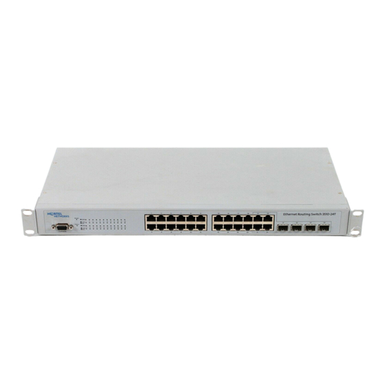
Page 23: Checking Leds On The Ethernet Routing Switch 3510-24T
Checking LEDs on the Ethernet Routing Switch 3510-24T Refer to the illustration and tables that follow for descriptions of the LEDs on the Ethernet Routing Switch 3510-24T. The tables describe LED operation for a switch that has completed its power-on self-tests. - Page 24 The power-on self test is complete, and the switch is operating normally. Blinking A nonfatal error occurred during the self-test. The switch failed the self-test. Table 6 10/100/1000 and Shared GBIC Port LEDs on the Ethernet Routing Switch 3510-24T Label Color/Status Description 1000 This port is set to operate at 1000 Mbps.
-
Page 25: Setting Ip Parameters For The Ethernet Routing Switch 3510-24T
To manage the switch using Telnet or SNMP or to perform TFTP operations, you must set certain IP parameters. For the initial setup of the Ethernet Routing Switch 3510-24T, you must set the following IP parameters: •... - Page 26 Select IP Configuration/Setup to display the IP Configuration/Setup menu. Note: The default management VLAN in the Ethernet Routing Switch 3510-24T is VLAN 1. To manage the switch, make sure the network management station is on the management VLAN or is connected to the management VLAN through routers.
- Page 27 In-Band Subnet Mask field. This value is based on the class of the entered IP address, either In-Band Switch IP address or In-Band Stack IP address. In the Default Gateway field, enter the default gateway address. Press Ctrl-C to return to the Main Menu. Installing the Ethernet Routing Switch 3510-24T...
- Page 28 Translation of the safety messages This section provides translations of the Caution, Danger, and Warning messages that appear within this document. Caution: This device is a Class A product. In a domestic environment, this device can cause radio interference, in which case the user may be required to take appropriate measures.
- Page 29 Questo prodotto non contiene parti riparabili dall ’utente. Aviso: Para evitar ferimento corporal de choque elétrico perigoso e atual, nunca remova a tampa superior do dispositivo. Não há nenhum componente usuário-user-serviceable para dentro. Installing the Ethernet Routing Switch 3510-24T...
- Page 30 Caution: Risk of explosion if battery is replaced with an incorrect type. Dispose of batteries according to instructions. Achtung: efahr der Explosion, wenn Batterie mit einer falschen Art ersetzt wird. Entledigen Sie sich Batterien entsprechend Anweisungen. Attention : Risque d'explosion si la batterie est remplacée avec un type incorrect. Débarassez-vous des batteries selon des instructions.
- Page 31 45 kg. Das Gehäuse des Switches ist nicht für solche Belastungen ausgelegt. Attention : ne placez pas d’unité d’alimentation BayStack 10 au-dessus de l’Ethernet Routing Switch 3510-24T. Les unités BayStack 10 pesant 45 kg, le boîtier n’est pas assez résistant pour supporter cette masse.
- Page 32 Caution: When mounting this device in a rack, do not stack units directly on top of one another in the rack. Each unit must be secured to the rack with appropriate mounting brackets. Mounting brackets are not designed to support multiple units. Achtung: Wenn diese Einheit in einem Rack montiert wird, muß...
- Page 33 Perigo: Use somente os cabos de poder que têm um trajeto aterrando. Sem uma terra apropriada, uma pessoa que toque o interruptor está no perigo de receber um choque elétrico. A falta de um trajeto aterrando ao interruptor pode resultar em emissões excessivas. Installing the Ethernet Routing Switch 3510-24T...
- Page 34 Warning: Disconnecting the AC power cord is the only way to turn off AC power to this device. Always connect the AC power cord in a location that can be reached quickly and safely in case of an emergency. Warnung: Das Gerät kann nur durch Ziehen des Netzsteckers ausgeschaltet werden. Schließen Sie das Netzkabel an einer Steckdose an, die in Notfällen schnell und sicher zugänglich ist.
- Page 35 Aviso: O equipamento ótico da fibra pode emitir-se o laser ou a luz infravermelha que podem ferir seus olhos. Nunca olhe em um porto da fibra ótica ou do conector. Suponha sempre que os cabos óticos da fibra estão conectados a uma fonte clara. Installing the Ethernet Routing Switch 3510-24T...
- Page 36 217326-A...
Need help?
Do you have a question about the 3510-24T and is the answer not in the manual?
Questions and answers