
Related Manuals for Patton electronics 2135


Summary of Contents for Patton electronics 2135
- Page 1 USER MANUAL Model 2135 Ethernet Micro-Bridge Part# 07M2135-UM SALES OFFICE Doc# 08303U2-001, (301) 975-1000 Rev. B TECHNICAL SUPPORT Revised 10/26/06 (301) 975-1007 An ISO-9001 http://www.patton.com Certified Company...
-
Page 2: Table Of Contents
However, this is no guarantee that interference will not occur in a particular installation. If the Model 2135 does cause interfer- ence to radio or television reception, which can be determined by dis-... -
Page 3: Service
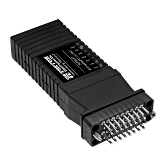
The Patton Model 2135 MicroBridge is an Ethernet Bridge that provides LAN extension when used in conjunction with a V.35 DCE device, such as a DSU/CSU, NTU, or router. The Model 2135 performs transparent Ethernet bridging and functions at the MAC level, thus is transparent to higher level protocols such as TCP/IP, DECnet, NET- BIOS, and IPX network protocols. -
Page 4: Ppp Operational Background
192.168.1.0/24 through 192.168.1.1/24. The address 192.168.1.1/24 is also the default gateway for the remote network. The above settings remove any routing/forwarding intelligence from the CPE. The associ- Patton Router 2135 Bridge Ethernet LAN PEC Device w/ Serial I/F Figure 1. Cisco router with serial interface, configured as PPP Half Bridge. -
Page 5: Installation
(center pin is +5V). The universal input power supply is equipped with a male IEC-320 connector. This power supply connects to the Model 2135 via a barrel jack on the rear panel. A variety of inter- national power cords are available for the universal power supply. -
Page 6: Configuration
Model 2135. Once you have configured your mux or other equipment to be connected to the 2135, the unit is ready for operation. Observe that the serial port of the 2135 is configured as a DTE and must con- nect to a DCE. -
Page 7: Appendix A - Specifications
DTR- Data Terminal Ready LED (yellow)- turns ON at power up to indicate to the DCE that the 2135 is active. CTS- Clear to Send LED (yellow) - turns ON when the 2135 is ready to receive data from the DCE. -
Page 8: Appendix B - Factory Replacement Parts
APPENDIX C 10BaseT Interface Pin Assignment (RJ-45 Female Connector) (DTE Configuration) Pin # Signal 1 TD + (data output from 2135) 2 TD - (data output from 2135) 3 RD + (data input to 2135) no connection no connection 6 RD -... -
Page 9: Appendix D - Terminal Interface Pin Assignment
APPENDIX D Terminal Interface Pin Assignment (M/34 Male Connector) Pin # Signal A GND (Earth Ground/Shield) B SGND (Signal Ground) D CTS (DCE Source) E DSR (DCE Source, Always On) F CD (DCE Source) H (DTR) (DTE Source) P TD (Transmit Data +, DTE Source) R RD (Receive Data +, DCE Source) - Page 10 Notes __________________________________________ __________________________________________ __________________________________________ __________________________________________ __________________________________________ __________________________________________ __________________________________________ __________________________________________ __________________________________________ __________________________________________ __________________________________________ __________________________________________ __________________________________________ __________________________________________ __________________________________________ __________________________________________ Notes __________________________________________ __________________________________________ __________________________________________ __________________________________________ __________________________________________ __________________________________________ __________________________________________ __________________________________________ __________________________________________ __________________________________________ __________________________________________ __________________________________________ __________________________________________ __________________________________________ __________________________________________ __________________________________________ Copyright © 2006 Patton Electronics Company All Rights Reserved...