
Summary of Contents for Axia xNode
- Page 1 Installation & User’s Guide Manual Rev 2.0 - January 2016 p/n 1490-00081-002...
- Page 2 If the equipment is used in a manner not specified by the manufacturer, the protection provided by the equipment may be impaired. © 2016 Axia Audio - Rev 2.0...
- Page 3 Gerät nicht auf einem Teppich, Poster oder andere Materialien welche die Lüftungsöffnungen beeinträchtigen könnten. Wird das Gerät anders als in der, vom Hersteller angegebenen Weise verwendet, kann der, durch das Gerät gegebene Schutz beeinträchtigt werden. © 2016 Axia Audio - Rev 2.0...
- Page 4 This device complies with the requirements of the EEC council directives: • 93/68/EEC (CE MARKING) • 73/23/EEC (SAFETY – LOW VOLTAGE DIRECTIVE) • 89/336/EEC (ELECTROMAGNETIC COMPATIBILITY) Conformity is declared to those standards: EN50081-1, EN50082-1. © 2016 Axia Audio - Rev 2.0...
- Page 5 Manual © 2014-2016 TLS Corp. Published by Axia Audio/TLS Corp. All rights reserved. TRADEMARKS Axia Audio and the Axia and xNode logos are trademarks of TLS Corp. All other trademarks are the property of their respective holders. NOTICE All versions, claims of compatibility, trademarks, etc. of hardware and software products not made by Axia Audio which are mentioned in this manual or accompanying material are informational only.
- Page 6 • All other questions, please email inquiry@telosalliance.com. VIA WORLD WIDE WEB: The Axia Audio web site has a variety of information which may be useful for product selection and support. The url is telosalliance.com. REGISTER YOUR PRODUCT Did you know that all Telos Alliance products come with a 5-Year Warranty? Take a moment to activate your coverage online at telosalliance.com/product-registration/ .
-
Page 7: Table Of Contents
AES67 Unicast Setup Chapter Five: AES xNode . . . . . . . . . . . . . . . . 26 Rear Panel . - Page 8 Axia Audio is a driving force behind the AES67 AoIP standard, and its networked AoIP radio consoles, audio interfaces, networked intercom, and software products continue to move AoIP adoption forward and help broadcasters streamline operations with cohesive, smart, and feature-rich AoIP ecosystems.
-
Page 9: Chapter One: Introducing The Xnode
GPIO Logic xNode: 6 GPIO Ports, each with 5 Opto Inputs and 5 Opto Outputs • Mixed Signal Input/Output xNode: 1 Mic/Line Analog Input, 2 Analog Line Inputs, 1 AES-3 Input, 3 Ana- log Line Outputs, 1 AES-3 Output, 2 GPIO Ports, each with 5 inputs and 5 outputs. -
Page 10: The Front Panel
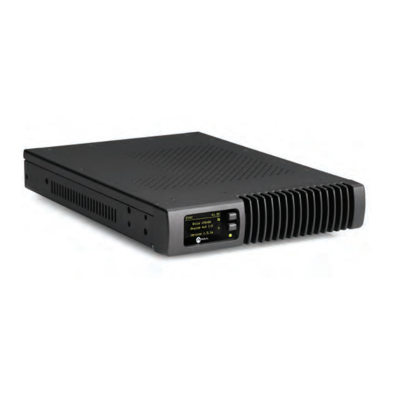
The Front Panel Figure 1-1: xNode Front Panel The xNode uses the OLED display on the left hand side to provide status information and assist with initialsetup. Figure 1-2: xNode OLED Display © 2016 Axia Audio - Rev 2.0... -
Page 11: Rear Panel
Chapter 4. AES/EBU Four AES-3 inputs and four AES-3 outputs are available in parallel through the RJ45 ports or the DB-25 ports. Pin- out information is available in Chapter 5. © 2016 Axia Audio - Rev 2.0... -
Page 12: Microphone
HTML interface (otherwise known as a web interface). Accessing this interface requires a PC that is on the same network as the xNode and has an IP address within the same subnet. Using a web browser, the IP address of the xNode is typed into the URL request field. - Page 13 The home page will show system information. (shown if ID assigned): An xNode can be assigned an ID which is used to assist with IP addressing and Node ID: channel numbering. The code version which is used by the xNode.
-
Page 14: Chapter Two: Configuration
Connect a cross over cable between a computer and the xNode or connect the xNode to the appropriately configured switch. • Set a static IP address to your computer that has a link to the xNode directly or through a network switch. (an IP address of 10.216.0.100 would be suitable) •... - Page 15 To resolve this you can select the System link under the Advanced Options to change the host name to something more descriptive (e.g. Studio1-MICs, TOC-AES1, SATRCK-GPIO1).With a descriptive host name ap- plied to the xNode, a listing of available audio streams will be displayed in a more descriptive manner, i.e., Host- Mic@Studio1-MICs Guest1@Studio1-MICs CD1@Ctrl1-AES WXYZ-tune@TOC-ANA1, etc.
-
Page 16: Assigning An Ip Address Manually
Once the xNode has the desired IP value, you can log into the HTML interface with a PC that has a static IP value within the same subnet as the xNode and connected to the same network. Later in this chapter the Simple Setup HTML interface is covered. -
Page 17: Iprobe Configuration
Once the xNode has been assigned an ID value, the device has an IP address that can be used to access its HTML configuration interface. Each input has been assigned a unique Livewire channel number. The next configuration steps are to enter in descriptive names to the inputs and outputs and to assign Livewire sources to the destinations. -
Page 18: Restoring Defaults
These inputs are known within the network as sources and go to Destinations. Destinations of the xNode are the audio outputs. The Name field is used for documenting what is connected to the audio output port. Channel field is where you select an audio stream from the network to provide audio for the out- put. -
Page 19: Chapter Three: The Xnode In Depth
The optional surface mount kit (p/n 2011-00077) consists of two brackets that are used to secure the xNode to a wall, under a desk, or almost any flat surface. The brackets secure to the side of the xNode, towards the front panel. There are four holes which are used for secur- ing metal work to the xNode. -
Page 20: Optional Rack Mount Kit
Figure 3-2 Outward configuration Figure 3-3: Inward configuration Optional Rack Mount kit The optional rack mount kit (p/n 2011-00076) provides the ability to secure the xNode into an equipment rack. Figure 3-4: Short rack ear Figure 3-5: Long rack ear... - Page 21 Figure 3-6: Spacer Single xNode Secure the short rack ear to one side of the xNode. Secure the long ear to the opposing side of the xNode. Figure 3-8 Double xNode Remove the top lid from both xNodes. Place two xNodes side by side. Place the spacer between the two xNodes.
-
Page 22: Home
Replace the lids on the xNodes. Secure the short rack ears to either side of the two xNodes. Figure 3-10 Web interface (System options) The first time an HTML request is issued to a xNode, a login and password is requested. The default authentication is: Username: user Password: (none) Home The home page shows system information and acts as the default page for xNodes. -
Page 23: Simple Setup
: Name of the device on the network. Up to 12 characters using only letters, numbers, or hyphens (no Host name spaces or special characters). Host name is auto populated when you assign an ID to the xNode providing a unique name. You may customize this field if you desire. - Page 24 Once the file is selected, pressing the Apply button will upload the software into the bank. The process will not interrupt the operation of the xNode. Once complete, the System page will return and the two banks will show versions of software.
-
Page 25: Qos (Audio Xnodes)
PTP category to allow the node to be a master of both PTP and the Livewire network or to be a slave to a PTP grand master but a master to the Livewire network. This permits the xNode to behave as a gateway of sorts for network synchronization between AES67 devices and legacy Livewire devices. -
Page 26: Meters (Audio Xnodes)
The meter page uses a Java script to provide real time meter representation of the audio at the inputs and outputs. The meter page shows a stereo channel or a mono channel based on the configuration of the xNode and the amount of channels enabled. -
Page 27: Mixer (Audio Xnodes)
Figure 3-13 The mixer view is organized with inputs into the xNode as rows and outputs from the xNode as columns. Inputs and outputs are composed of physical connections and network streams. In the case of an AES/EBU input on port 1 of the AES/EBU xNode turning into the first network stream source of the xNode, the mixer will show the following view (without the arrows, which are added for clarity). - Page 28 Figure 3-14 Another example with the AES/EBU xNode is all four physical inputs are turned into the first four network stream sources and a fifth network stream source is the sum of three AES/EBU inputs as shown in figure 3-15.
-
Page 29: Destinations (Audio Xnode)
With the introduction of 2.0 software, the Desti- nation page has a new distinction of being more than an xNode outputs view but also a network stream input view. -
Page 30: Sources (Audio Xnode)
The Sources page typically defines the physical audio inputs of the xNode. The corresponding network streams are given a name and a unique channel number that is used to distribute through the network. The xNode provides an auto-numbering process when you ID the xNode through the node ID process described in Chapter 2. - Page 31 If the triangle is blinking, the port is configured for Unicast, but there is no active connection. • When the triangle is displayed solid on, there is a Unicast Link established to that port. © 2016 Axia Audio - Rev 2.0...
-
Page 32: Chapter Four: Analog Xnode
Rear Panel Figure 4-1: Analog xNode Rear Panel The analog xNode uses RJ45 style connectors and 25 pin D-sub connectors for audio I/O, providing an option to either use standard CAT5e patch cables or D-Sub breakout cables for audio wiring. - Page 33 Channel 4a/7 + Channel 4a/7 Gnd Channel 3b/6 - Channel 3a/5 + Channel 3a/5 Gnd Channel 2b/4 - Channel 2a/3 + Channel 2a/3 Gnd Channel 1b/2 - Channel 1a/1 + Channel 1a/1 Gnd © 2016 Axia Audio - Rev 2.0...
-
Page 34: Chapter Five: Aes Xnode
2 channel AES inputs as different sources and generate up to 8 Livewire dual mono sources. The AES xNode provides four AES outputs. By default the outputs will be an AES stream based on a single Livewire stream. The option is available to create an AES stream (Left and Right) which is composed from two dif- ferent Livewire streams. - Page 35 AES Ch1 - Not Used Not Used Not Used Not Used Not Used Not Used Not Used AES Ch4 - AES Ch3 + AES Ch3 Gnd AES Ch2 - AES Ch1 + AES Ch1 Gnd © 2016 Axia Audio - Rev 2.0...
-
Page 36: Chapter Six: Microphone Xnode
The microphone xNode has four mono inputs. The microphone xNode provides four analog 2-channel outputs, line level. By default the outputs will be stereo au- dio from an audio source from the network. This may be configured differently so that the 2 channel analog output delivers two mono streams. -
Page 37: 2016 Axia Audio - Rev 2.0
Not Used Not Used MIC Ch4 + MIC Ch4 Gnd Not Used MIC Ch3 + MIC Ch3 Gnd Not Used MIC Ch2 + MIC Ch2 Gnd Not Used MIC Ch1 + MIC Ch1 Gnd © 2016 Axia Audio - Rev 2.0... -
Page 38: 2016 Axia Audio - Rev 2.0
Channel 4a/7 + Channel 4a/7 Gnd Channel 3b/6 - Channel 3a/5 + Channel 3a/5 Gnd Channel 2b/4 - Channel 2a/3 + Channel 2a/3 Gnd Channel 1b/2 - Channel 1a/1 + Channel 1a/1 Gnd © 2016 Axia Audio - Rev 2.0... -
Page 39: Chapter Seven: Gpio Xnode
GPIO xNode The GPIO xNode provides 6 DA-15 ports. Each port provides 5 GPI (opto isolated inputs) and 5 GPO (solid state relays). Each port is capable of driving a combined current of 100mA. Each GPI pin should be limited to 20mA of current. - Page 40 Axia GPIO accessory modules are designed to interface directly to the GPIO port. The DA-15 connector on the back of an accessory module is a direct pin-to-pin match to the GPIO port of the xNode. Premade cables of this configu- ration are commonly available through companies that specialize in interconnect cable assembly products.
- Page 41 Figure 7-6 The Axia accessory modules use the 5vDC supply to illuminate LED based buttons. So a one-to-one pin connection is all that is needed between any accessory modules and a GPIO port. Note that all of the inputs and outputs on a specific GPIO port are “grouped together”. The 5 “Outputs” are on 5 separate output pins, however, they share the same “Common Return”...
-
Page 42: Simple Setup
Simple Setup The GPIO xNode has a simple setup page which provides access to the node ID (a node ID was likely already assigned from the front panel at install) and configuration of the 6 GPIO ports. Included also in the page is a Java script which provides status on each of the inputs and outputs. -
Page 43: Other Web Interfaces
Other Web Interfaces The GPIO xNode does not have any complexity to it, so there are no advance web pages to worry about. Home The Home page is the default page and provides information on the device ID, software version, system temp, net- work interface status, power supply status, and uptime. -
Page 44: Chapter Eight: Mixed Signal Xnode
AES/EBU input, three analog stereo outputs, one AES/EBU output, and 2 GPIO ports (5GPI/5GPO per port). Rear Panel The Mixed Sigal xNode uses RJ45 connectors for analog and AES audio, and an XLR connector for the selectable Mic input. - Page 45 INPUT External Series Resistor 680 @ 1/4 watt 1.8k @ 1/2 watt 3.9k @ 1 watt Using external power supplies is the recommended method to avoid possible ground loops between equipment. Figure 8-3 © 2016 Axia Audio - Rev 2.0...
- Page 46 Axia GPIO accessory modules are designed to interface directly to the GPIO port. The DA-15 connector on the back of an accessory module is a direct pin-to-pin match to the GPIO port of the xNode. Premade cables of this configura- tion are commonly available through companies that specialize in interconnect cable assembly products.
-
Page 47: Simple Setup
– The Pathfinder series of products has the ability to observe GPIO activity as well as Pathfinder control trigger GPO activity. Nothing is required to configure in the GPIO xNode, all the configuration is done in Pathfinder. Please refer to Pathfinder documentation for detailed information. -
Page 48: Appendix A: Gpio Logic Table Samples
Input Common Common for all 5 inputs Connect to power supply of source device or to Pin 9 NOT CONNECTED OUTPUT COMMON RETURN ØV (GND) SOURCE +5 V GPIO v.”ZA” 4/2009 POWER SOURCE © 2016 Axia Audio - Rev 2.0... -
Page 49: Gpio Control Room Guest Microphone Logic
Source Supply Common for all 5 inputs Connect to power supply of source device or to Pin 9 NOT CONNECTED OUTPUT COMMON RETURN ØV (GND) SOURCE +5 V POWER SOURCE GPIO v.”ZA” 4/2009 © 2016 Axia Audio - Rev 2.0... -
Page 50: Gpio Producer's Microphone Logic
Source Supply Common for all 5 inputs Connect to power supply of source device or to Pin 9 NOT CONNECTED OUTPUT COMMON RETURN ØV (GND) SOURCE +5 V POWER SOURCE GPIO v.”ZA” 4/2009 © 2016 Axia Audio - Rev 2.0... -
Page 51: Gpio Line Input Logic
Source Supply Common for all 5 inputs Connect to power supply of source device or to Pin 9 NOT CONNECTED OUTPUT COMMON RETURN ØV (GND) SOURCE +5 V POWER SOURCE GPIO v.”ZA” 4/2009 © 2016 Axia Audio - Rev 2.0... -
Page 52: Gpio Codec Logic
Source Supply Common for all 5 inputs Connect to power supply of source device or to Pin 9 NOT CONNECTED OUTPUT COMMON RETURN ØV (GND) SOURCE +5 V POWER SOURCE GPIO v.”ZA” 4/2009 © 2016 Axia Audio - Rev 2.0... -
Page 53: Gpio Telephone Hybrid Logic
Source Supply Common for all 5 inputs Connect to power supply of source device or to Pin 9 NOT CONNECTED OUTPUT COMMON RETURN ØV (GND) SOURCE +5 V POWER SOURCE GPIO v.”ZA” 4/2009 © 2016 Axia Audio - Rev 2.0... -
Page 54: Gpio Control Room Monitor Logic
Source Supply Common for all 5 inputs Connect to power supply of source device or to Pin 9 NOT CONNECTED OUTPUT COMMON RETURN ØV (GND) SOURCE +5 V POWER SOURCE GPIO v.”ZA” 4/2009 © 2016 Axia Audio - Rev 2.0... -
Page 55: Gpio Computer Playback Device Logic
Source Supply Common for all 5 inputs Connect to power supply of source device or to Pin 9 NOT CONNECTED OUTPUT COMMON RETURN ØV (GND) SOURCE +5 V POWER SOURCE GPIO v.”ZA” 4/2009 © 2016 Axia Audio - Rev 2.0... -
Page 56: Appendix B: Xnode Specifications
• Any input to any output: +/- 0.5 dB, 20 Hz to 20 kHz Latency • Analog Input to Analog Output, 2.75ms including network, converters, and mixing process • Digital Input to Digital Output, 1.75ms including network mixing engine (ASRC off) © 2016 Axia Audio - Rev 2.0... -
Page 57: Dynamic Range
• 8.5” (22 cm) wide; two may be mounted side-by-side in a standard 1RU rack space (with accessory mounting kit) • 1.72” (4.4 cm) height, 11.75” (30 cm) depth • Shipping Weight: 7 lbs. (3.2 kg.) • Shipping Dimensions: 17” (43.2 cm) length, • 13” (33 cm) width, 7” (17.8 cm) height © 2016 Axia Audio - Rev 2.0... -
Page 58: Appendix C: Aes67
AES67 standard requires device to use IEEE1588 network time protocol standard. The Synchronization and QoS page of the xNode provides the controls to establish the xNode as a system PTP master or slave to a grand master. Clock mode options allow selecting the operation suitable to the system in which the xNode is being deployed. -
Page 59: Aes67 Multicast Connection Setup
AES67 Multicast connection setup xNode transmits a multicast streams as soon as Source is configured with a Livewire channel number or multicast IP address and Stream Mode is set to a value other than “disabled”. AES67 requires devices to support reception of at least 1ms frames this corresponds to “Low Latency Stereo”... -
Page 60: Aes67 Unicast Setup
• Send only connection (SIP Invitation with sendonly attribute specified in the SDP block). After answering, xNode will start receiving the stream which can be 16 bit or 24 bit with channel count from 1 to 8. This type of a connection required the corresponding Destination to be not configured (empty Channel/Address) field. - Page 61 The xNode makes a SIP call to the specified source. The call is receive only (issued with recvonly SIP/SDP media attribute specified). The xNode will provide status of the unicast connection on the front panel. Small triangle icons below the meters show the current status: •...
-
Page 62: Appendix D: Telos Alliance Limited Warranty
(+1) 216-241-7225. If Telos authorizes the performance of warranty service, the defective Product must be delivered to: Telos, 1241 Superior Avenue, Cleveland, Ohio 44114 or other company repair center as may be specified by Telos at the time of claim. © 2016 Axia Audio - Rev 2.0... - Page 63 Telos. If no repairs are required, the $500 fee will be retained by Telos as an evalu- ation charge. If repairs are required, the $500 fee will be applied to the total cost of the repair. © 2016 Axia Audio - Rev 2.0...
- Page 64 Axia Audio, a Telos Alliance Company • 1241 Superior Ave. • Cleveland, Ohio, 44114, USA • +1.216.241.7225 • TelosAlliance.com © 2016 TLS Corp. Axia®. The Telos Alliance®. All Rights Reserved. F16/16018...
Need help?
Do you have a question about the xNode and is the answer not in the manual?
Questions and answers