Table of Contents
Advertisement
INSTALLER: Leave this manual with party responsible for use and operation.
OWNER: Retain this manual for future reference.
NOTICE: DO NOT discard this manual!
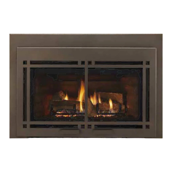
RUBY
SERIES
Models: MDVI30IN
MDVI35IN
MDVI30IL
MDVI35IL
This appliance may be installed as an OEM
installation in manufactured home (USA
only) or mobile home and must be installed
in accordance with the manufacturer's
instructions and the Manufactured Home
Construction and Safety Standard, Title 24
CFR, Part 3280 in the United States, or the
Standard for Installation in Mobile Homes,
CAN/CSA Z240 MH Series, in Canada.
This appliance is only for use with the type(s)
of gas indicated on the rating plate. This
appliance is not convertible for use with other
gases, unless a certifi ed kit is used.
In the Commonwealth of Massachusetts installation must be
performed by a licensed plumber or gas fi tter.
See Table of Contents for location of additional Commonwealth
of Massachusetts requirements.
Majestic • MDVI30IN, MDVI35IN, MDVI30IL, MDVI35IL Installation Manual • 2205-980 Rev. H • 12/16
Installation Manual
Installation and Appliance Setup
WARNING:
FIRE OR EXPLOSION HAZARD
Failure to follow safety warnings exactly
could result in serious injury, death, or
property damage.
• DO NOT store or use gasoline or other fl am-
mable vapors and liquids in the vicinity of this
or any other appliance.
• What to do if you smell gas
- DO NOT try to light any appliance.
- DO NOT touch any electrical switch. DO
NOT use any phone in your building.
- Leave the building immediately.
- Immediately call your gas supplier from
a neighbor's phone. Follow the gas sup-
plier's instructions.
- If you cannot reach your gas supplier, call
the fi re department.
• Installation and service must be performed
by a qualifi ed installer, service agency, or the
gas supplier.
DANGER
DO NOT TOUCH GLASS
NEVER ALLOW CHILDREN
A barrier designed to reduce the risk of
burns from the hot viewing glass is provided
with this appliance and shall be installed for
the protection of children and other at-risk
individuals.
HOT GLASS WILL
CAUSE BURNS.
UNTIL COOLED.
TO TOUCH GLASS.
1
Advertisement
Table of Contents

Subscribe to Our Youtube Channel
Related Manuals for Majestic MDVI30IN


Summary of Contents for Majestic MDVI30IN
- Page 1 In the Commonwealth of Massachusetts installation must be performed by a licensed plumber or gas fi tter. See Table of Contents for location of additional Commonwealth of Massachusetts requirements. Majestic • MDVI30IN, MDVI35IN, MDVI30IL, MDVI35IL Installation Manual • 2205-980 Rev. H • 12/16...
-
Page 2: Table Of Contents
F. Installing Adaptor and Termination Cap ....16 = Contains updated information. Majestic • MDVI30IN, MDVI35IN, MDVI30IL, MDVI35IL Installation Manual • 2205-980 Rev. H • 12/16... -
Page 3: Installation Standard Work Checklist
_____________________________________________________________________________________ _________________________________________________________________________________________________ _________________________________________________________________________________________________ Comments Communicated to party responsible ____________________ by ______________________on ___________ (Builder / Gen. Contractor/) (Installer) (Date) = Contains updated information. 2205-982 Rev. B 11/16 Majestic • MDVI30IN, MDVI35IN, MDVI30IL, MDVI35IL Installation Manual • 2205-980 Rev. H • 12/16... -
Page 4: Product Specifi C And Important Safety Information
25,000 13,000 (2000-4500 FT) 35,000 19,500 (0-2000 FT) MDVI35IN (NG) CANADA 32,500 17,500 (2000-4500 FT) 31,500 16,500 (0-2000 FT) MDVI35IL (LP) CANADA 27,500 15,000 (2000-4500 FT) Majestic • MDVI30IN, MDVI35IN, MDVI30IL, MDVI35IL Installation Manual • 2205-980 Rev. H • 12/16... -
Page 5: Getting Started
Call a qualifi ed service technician to inspect the appliance and to replace any part of the control system and/or gas control which has been under water. Majestic • MDVI30IN, MDVI35IN, MDVI30IL, MDVI35IL Installation Manual • 2205-980 Rev. H • 12/16... -
Page 6: Framing And Clearances
4-11/16 4-5/8 *Note: Location G on Figure 14.1 is measuring the appliance depth, for installation depth reference Location G on Figure 5.2. Figure 3.1 Appliance Dimensions Majestic • MDVI30IN, MDVI35IN, MDVI30IL, MDVI35IL Installation Manual • 2205-980 Rev. H • 12/16... -
Page 7: Decorative Fronts
CRDI30BZ CRDI35BK CRDI35BZ 13-13/16 4-1/2 23-1/2 CRDI30BK MDVI30IN/IL CRDI30BZ 15-13/16 4-1/2 37-15/16 25-1/2 CRDI35BK MDVI35IN/IL CRDI35BZ Figure 3.2 Decorative Front Dimensions - CRDI30BK, CRDI30BZ, CRDI35BK, CRDI35BZ Majestic • MDVI30IN, MDVI35IN, MDVI30IL, MDVI35IL Installation Manual • 2205-980 Rev. H • 12/16... -
Page 8: Fireplace Size Requirements
The sidewalls and top structure of the fi rebox may not be altered with the exception of removable baffl es and dampers. Majestic • MDVI30IN, MDVI35IN, MDVI30IL, MDVI35IL Installation Manual • 2205-980 Rev. H • 12/16... - Page 9 **Unit depth is measured to the back of the surround to give the depth needed for installation. In addition to these dimensions, also reference Clearances and Mantel Projections (Section 4.B). Figure 4.2 Firebox Opening - Standard Surround Majestic • MDVI30IN, MDVI35IN, MDVI30IL, MDVI35IL Installation Manual • 2205-980 Rev. H • 12/16...
-
Page 10: Mantel And Wall Projections
fi rebox. Combustible facings must not extend behind the insert surround. For non-combustible material specifi cations refer to Section 1.E. Figure 4.4 Mantel Clearances Majestic • MDVI30IN, MDVI35IN, MDVI30IL, MDVI35IL Installation Manual • 2205-980 Rev. H • 12/16... -
Page 11: Termination Location And Vent Information
Over 20/12 to 21/12 ..........8.0 * H minimum may vary depending on regional snowfall. Refer to local codes. Figure 5.1 Minimum Height From Roof To Lowest Discharge Opening Majestic • MDVI30IN, MDVI35IN, MDVI30IL, MDVI35IL Installation Manual • 2205-980 Rev. H • 12/16... -
Page 12: Installation Preparation
The control is accessed by removing the lower access needs. panel behind the decorative front. Reference the specifi c RC200 user instructions for confi guring the remote to the appliance. Majestic • MDVI30IN, MDVI35IN, MDVI30IL, MDVI35IL Installation Manual • 2205-980 Rev. H • 12/16... -
Page 13: Installing Vent Pipe And Appliance
INLET AIR STARTING COLLAR NOTE: TO ACHIEVE OPTIMUM PERFOR- MANCE OF INSERT, MINIMIZE OR AVOID BENDS IN EXHAUST VENT PIPE. STARTING COLLAR BRACKET EXHAUST STARTING COLLAR Figure 7.1 Majestic • MDVI30IN, MDVI35IN, MDVI30IL, MDVI35IL Installation Manual • 2205-980 Rev. H • 12/16... -
Page 14: Connecting Vent Pipe
• Trim chimney top plate to minimize excess overhang or bend over fl ue tile (see Figure 7.2). • Place 3/8 inch bead of 300ºF silicone on fl ue tile top. Majestic • MDVI30IN, MDVI35IN, MDVI30IL, MDVI35IL Installation Manual • 2205-980 Rev. H • 12/16... -
Page 15: Placing, Securing And Leveling The Appliance
Majestic • MDVI30IN, MDVI35IN, MDVI30IL, MDVI35IL Installation Manual • 2205-980 Rev. H • 12/16... -
Page 16: Remote Control
Over 10/12 to 11/12 ..3.25 * H minimum may vary depending on regional snowfall. Refer to local codes. Figure 7.4 Minimum Height from Roof to Lowest Discharge Opening Majestic • MDVI30IN, MDVI35IN, MDVI30IL, MDVI35IL Installation Manual • 2205-980 Rev. H • 12/16... - Page 17 • Depending on the chimney cleanliness, consider using the full length intake so as to lessen the possibility of sense rod contamination and fl ame rectifi cation issues. Figure 7.6 Majestic • MDVI30IN, MDVI35IN, MDVI30IL, MDVI35IL Installation Manual • 2205-980 Rev. H • 12/16...
-
Page 18: Electrical Information
Batteries should only be placed in the battery pack when 110-120 VAC is not available. See Section 3.I of Owner’s manual. Control Module Operation See Section 3.J of Owner’s Manual for control module operation instructions. Majestic • MDVI30IN, MDVI35IN, MDVI30IL, MDVI35IL Installation Manual • 2205-980 Rev. H • 12/16... -
Page 19: Optional Accessories Requirements
AUX 200 MODULE FUSE WIRE TO CONTROL ASSEMBLY MODULE FUSE WIRE ASSEMBLY BLOWER RECEPTICLE Figure 8.1 Intellifi re Plus Pilot Ignition (IPI) Wiring Diagram and Fan Wiring Diagram Majestic • MDVI30IN, MDVI35IN, MDVI30IL, MDVI35IL Installation Manual • 2205-980 Rev. H • 12/16... -
Page 20: Gas Information
4500 feet (1370 m). • If substituting for these components, please consult local codes for compliance. Check with your local gas utility to determine proper orifi ce size. Majestic • MDVI30IN, MDVI35IN, MDVI30IL, MDVI35IL Installation Manual • 2205-980 Rev. H • 12/16... -
Page 21: Air Shutter Setting
NOTICE: If sooting occurs, provide more air by opening the air shutter. Figure 9.1 Air Shutter Air Shutter Settings MDVI30IN 3/8 in. MDVI35IN 3/8 in. MDVI30IL 1/2 in. MDVI35IL 1/2 in. Majestic • MDVI30IN, MDVI35IN, MDVI30IL, MDVI35IL Installation Manual • 2205-980 Rev. H • 12/16... -
Page 22: Finishing
For non-combustible material specifi cations refer to section 1.E. EXISTING NON-COMBUSTIBLE FACING 12 IN. MAX. 2 IN. MAX. 12 IN. MIN. 10 IN. MIN. Figure 10.1 Mantel Clearance Majestic • MDVI30IN, MDVI35IN, MDVI30IL, MDVI35IL Installation Manual • 2205-980 Rev. H • 12/16... -
Page 23: Appliance Setup
Using non-listed accessories bottom latches. could result in a safety hazard and will void the warranty. • Reinstall door or decorative front. Majestic • MDVI30IN, MDVI35IN, MDVI30IL, MDVI35IL Installation Manual • 2205-980 Rev. H • 12/16... -
Page 24: Place The Lava Rock
PILOT AREA EMBERS PLACED IN FRONT OF PORTS EMBERS PLACED ON PORTS EMBERS PLACED IN FRONT OF PORTS EMBERS PLACED ON PORTS Figure 11.3 Placement of Embers Majestic • MDVI30IN, MDVI35IN, MDVI30IL, MDVI35IL Installation Manual • 2205-980 Rev. H • 12/16... -
Page 25: Install The Log Assembly
See Figure 4 for slot detail. REAR TABS REAR TABS Figure 3. Rear Tabs Figure 4. Log #1 Placement Slots Figure 5. Log #1 Installed Majestic • MDVI30IN, MDVI35IN, MDVI30IL, MDVI35IL Installation Manual • 2205-980 Rev. H • 12/16... - Page 26 fl at spot on Log #1 and then setting the other end of Log #4 in the fl at spot on Log #2. See Figure 11. LOG #4 LOG #4 LOG #5 LOG #5 Figure 10. Log #4 and Log #5 Figure 11. Log #4 Installed Majestic • MDVI30IN, MDVI35IN, MDVI30IL, MDVI35IL Installation Manual • 2205-980 Rev. H • 12/16...
- Page 27 Log #6 as shown in Figure 14 by placing the grate tine groove into the grate tine and resting the log in the fl at area on Log #2 (left side of log). GRATE TINE GROOVE GRATE TINE GROOVE Figure 13. Log #6 Detail Figure 14. Log #6 Installed 2206-955C Majestic • MDVI30IN, MDVI35IN, MDVI30IL, MDVI35IL Installation Manual • 2205-980 Rev. H • 12/16...
-
Page 28: Log Placement Instructions
See Figure 4 for slot detail. REAR TABS REAR TABS Figure 3. Rear Tabs Figure 4. Log #1 Placement Slots Figure 5. Log #1 Installed Majestic • MDVI30IN, MDVI35IN, MDVI30IL, MDVI35IL Installation Manual • 2205-980 Rev. H • 12/16... - Page 29 LOG #6 Figure 10. Log #4 and Log #6 - Back Views Figure 11. Log #4 and Log #6 - Front Views Figure 12. Log #4 installed Majestic • MDVI30IN, MDVI35IN, MDVI30IL, MDVI35IL Installation Manual • 2205-980 Rev. H • 12/16...
- Page 30 fi rebox. LOG #6 CONTACTS BACK OF FIREBOX LOG #6 CONTACTS BACK OF FIREBOX Figure 15. Log #6 Installed 2205-955C Majestic • MDVI30IN, MDVI35IN, MDVI30IL, MDVI35IL Installation Manual • 2205-980 Rev. H • 12/16...
-
Page 31: Install Decorative Front/Surround
Contact your dealer or Hearth & Home Technologies if the barrier is not present or help is needed to properly install one. For more information refer to the instructions supplied with your decorative front. Majestic • MDVI30IN, MDVI35IN, MDVI30IL, MDVI35IL Installation Manual • 2205-980 Rev. H • 12/16... -
Page 32: Reference Materials
FLEX3-30: One 3 inch fl exible liner expands to 30 feet. FLEX-CNCT: Connector kit - 3 inch liner to 3 inch liner, one connector per kit. Majestic • MDVI30IN, MDVI35IN, MDVI30IL, MDVI35IL Installation Manual • 2205-980 Rev. H • 12/16... -
Page 33: Accessories
Please contact your Majestic dealer with any questions or concerns. For the location of your nearest Majestic dealer, please visit www.majesticproducts.com. Printed in U.S.A. - Copyright 2016 Majestic • MDVI30IN, MDVI35IN, MDVI30IL, MDVI35IL Installation Manual • 2205-980 Rev. H • 12/16...
Need help?
Do you have a question about the MDVI30IN and is the answer not in the manual?
Questions and answers