
Related Manuals for Patton electronics CopperLink 2155


Summary of Contents for Patton electronics CopperLink 2155
- Page 1 Part# 07M2155 Doc# 032111U Rev. A Revised 2/12/03 An ISO-9001Certified Company USER MANUAL MODEL 2155 CopperLink Ethernet Extender SALES OFFICE (301) 975-1000 TECHNICAL SUPPORT (301) 975-1007...
-
Page 2: Table Of Contents
A.11 Humidity ... 15 A.12 Dimensions ... 15 A.13 Weight ... 15 Models 2155 Factory Replacement Parts and Accessories... 16 Models 2155 Interface Pin Assignment ... 17 C.1 10Base-T Interface ... 17 RJ-45 ... 17 C.2 CopperLink Interface ... 17 RJ-45 ... 17... -
Page 3: Warranty Information
The Model 2155 has been tested and found to comply with the limits for a Class A computing device in accordance with specifications in Subpart B of Part 15 of FCC rules, which are designed to provide rea- sonable protection from such interference in a commercial installation. -
Page 4: Service
1.3 SERVICE All warranty and non-warranty repairs must be returned freight prepaid and insured to Patton Electronics. All returns must have a Return Materi- als Authorization number on the outside of the shipping container. This number may be obtained from Patton Electronics Technical Services at: •... -
Page 5: General Information
LAN connections between peered Ethernet LANs, remote PC’s, or any other network enabled 10Base-T device. Operating in pairs, a Model 2155/L (local) located at one end of the LAN extension and a Model 2155/R (remote) at the other end, these units can automatically forward LAN broadcasts, multicasts, and frames across a 2- wire voice-grade twisted-pair link. - Page 6 Figure 1. Typical application The 2155/L and 2155/R work together to create a transparent extension between two peered Ethernet LANs. Figure 1 shows a typical point-to- point application.
-
Page 7: Installation
Follow the steps below to connect the CopperLink interfaces. Note Model 2155 units work in pairs. One of the units must be a Model 2155/L (local) and the other unit must be a Model 2155/R (remote). 3.0 INSTALLATION... -
Page 8: Connecting 10Base-T Ethernet Port To Pc (Dte)
3.2 CONNECTING 10BASE-T ETHERNET PORT TO PC (DTE) The 10Base-T interface is configured as DTE (Data Terminal Equip- ment). If the Model 2155 is to to connect to another DTE device such as a 10Base-T network interface card, construct a 10Base-T crossover cable and connect the wires as shown in Figure 4. -
Page 9: Connecting Power
3.4 CONNECTING POWER An external AC or DC power supply is available separately. This connec- tion is made via the barrel jack on the rear panel of the Model 2155. No configuration is necessary for the power supply (See Appendix B on page 16 for domestic and international power supply and cord options). -
Page 10: External 48 Vdc Power Supply
An approved external power supply that incorporates a disconnect device must be used and positioned within easy reach of the operator’s position. Caution Connect the equipment to a 5 VDC source that is electri- cally isolated from the AC source. The 5 VDC source is to be reliably connected to earth. -
Page 11: Operation
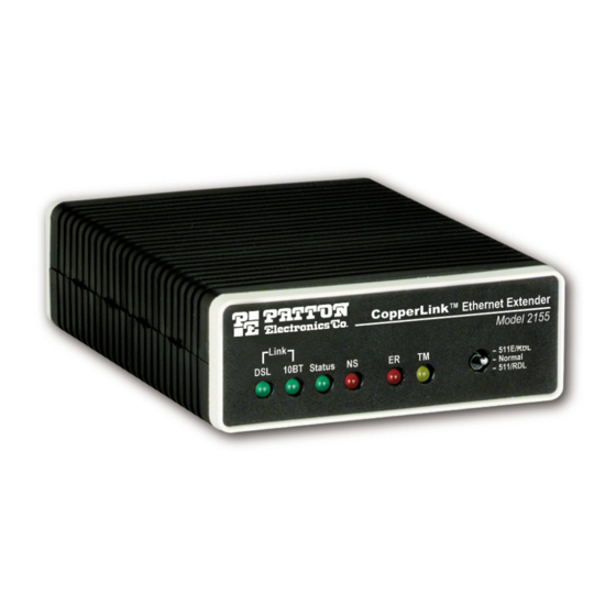
LED status monitors. 4.1 FRONT PANEL LED STATUS MONITORS The Model 2155 features six front-panel LEDs that monitor connections on the DSL and 10Base-T links, signaling, error and test modes. Figure 7 shows the front panel location of each LED. Table 1 describes the LED functions. - Page 12 Table 1: LED status monitor indications DSL Link (Active Green) Solid green (On) indicates that the end to end DSL Framer Link is up, signifying that the link across the DSL span is active. The DSL Link LED is Off when the Status Blinks yellow from one to eleven times to indicate system status.
-
Page 13: Test Modes
RDL initiated To use the Remote Digital Loopback tests, do the following: 1. Locate the 511/RDL toggle switch on the front panel of the 2155 and move it DOWN. This initiates the RDL and sends a 511 pattern into the loop. If any errors are present, the local modem’s red “ER” LED will blink. -
Page 14: Specifications
APPENDIX A SPECIFICATIONS A.1 GENERAL CHARACTERISTICS • Compact low cost plug-and-play router • 10Base-T Ethernet • Unlimited host support • Six front panel LEDs indicate DSL & 10BT Link, No Signal, Error, and test modes status • Convenient and standard RJ connectors for Ethernet and line •... -
Page 15: Connectors
A.7 CONNECTORS RJ-45 on line side; shielded RJ-45 on Ethernet port A.8 POWER SUPPLY External 100–240 VAC, 50–60 Hz (universal input option), +5 VDC out- put; 48 VDC (optional), 5 watts, +5 VDC output A.9 TEMPERATURE RANGE 32–122°F (0–50°C) A.10 ALTITUDE 0–15,000 feet (0–4,572 meters) A.11 HUMIDITY 5–95% non-condensing... -
Page 16: B Models 2155 Factory
REPLACEMENT PARTS AND ACCESSORIES Patton Model # 2155 Base Models 2155/L CopperLink Ethernet Extender; Line: RJ-11 (Local) 2155/R CopperLink Ethernet Extender; Line: RJ-11 (Remote) 2155-2PK CopperLink Ethernet Extender Kit: includes one local (L) and one remote (R) Model 2157 User Manual... -
Page 17: Models 2155 Interface Pin Assignment
• Pin 4: RING • Pin 5: TIP • Pins 1, 2, 3, 6, 7, & 8: no connection APPENDIX C 1 TX+ (data output from 2155) 2 TX- (data output from 2155) 3 RX+ (data input to 2155) 4 (no connection) - Page 18 Notes ________________________________________________________ ________________________________________________________ ________________________________________________________ ________________________________________________________ ________________________________________________________ ________________________________________________________ ________________________________________________________ ________________________________________________________ ________________________________________________________ ________________________________________________________ ________________________________________________________ ________________________________________________________ ________________________________________________________ ________________________________________________________ ________________________________________________________ ________________________________________________________ ________________________________________________________ ________________________________________________________ ________________________________________________________ ________________________________________________________ ________________________________________________________ ________________________________________________________ ________________________________________________________ ________________________________________________________ ________________________________________________________...
- Page 19 Notes ________________________________________________________ ________________________________________________________ ________________________________________________________ ________________________________________________________ ________________________________________________________ ________________________________________________________ ________________________________________________________ ________________________________________________________ ________________________________________________________ ________________________________________________________ ________________________________________________________ ________________________________________________________ ________________________________________________________ ________________________________________________________ ________________________________________________________ ________________________________________________________ ________________________________________________________ ________________________________________________________ ________________________________________________________ ________________________________________________________ ________________________________________________________ ________________________________________________________ ________________________________________________________ ________________________________________________________ ________________________________________________________...
- Page 20 Notes ________________________________________________________ ________________________________________________________ ________________________________________________________ ________________________________________________________ ________________________________________________________ ________________________________________________________ ________________________________________________________ ________________________________________________________ ________________________________________________________ ________________________________________________________ ________________________________________________________ ________________________________________________________ ________________________________________________________ ________________________________________________________ ________________________________________________________ ________________________________________________________ ________________________________________________________ ________________________________________________________ ________________________________________________________ ________________________________________________________ ________________________________________________________ Copyright © 2002 Patton Electronics Company All Rights Reserved.