
Related Manuals for LG LRG3061ST


Summary of Contents for LG LRG3061ST
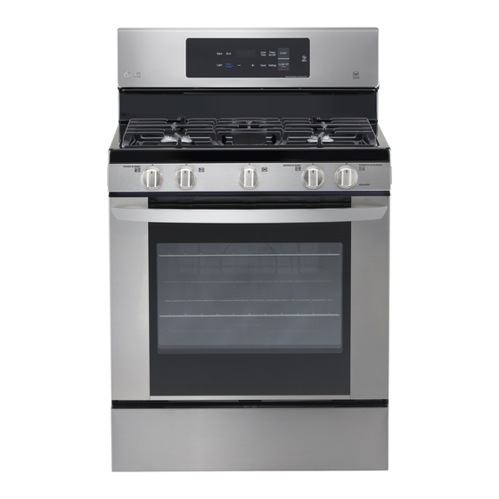
- Page 1 Internal Use Only 30” Freestanding Gas Range SERVICE MANUAL MODEL: LRG3061ST LRG3061BD CAUTION BEFORE SERVICING THE UNIT, READ THE SAFETY PRECAUTIONS IN THIS MANUAL. Mar, 2016 P/NO : MFL63290119 Printed in Korea...
-
Page 2: Safety Precautions
SAFETY PRECAUTIONS • Repairs of the appliance should be carried out by a licensed technician only. Incorrect repairs may result in dangerous situations. If you need repairs, contact an LG Service Center or your dealer. • If the power cord is defective, it must be replaced by a qualified service agent with a UL listed range cord. -
Page 3: Table Of Contents
TABLE OF CONTENTS GENERAL - - - - - - - - - - - - - - - - - - - - - - - - - - - - - - - - - - - - - - - - - - - - - - - - - - - - - - - - - - - - - - - - - - - - - - - - - - - - - - - - - - - - - - - - - - - - - - - - 1-1 ~ 1-5 •... - Page 4 (Page) COMPONENT TEST - - - - - - - - - - - - - - - - - - - - - - - - - - - - - - - - - - - - - - - - - - - - - - - - - - - - - - - - - - - - - - - - - - - - - - - - - - - - - - - - 4-1 ~ 4-4 •...
-
Page 5: General
GENERAL IMPORTANT SAFETY INSTRUCTIONS Read and follow all instructions before using your oven to prevent the risk of fire, electric shock, injury to person, or damage when using the range. This guide don’t cover all possible conditions that may occur. For further assistance contact your service agent or manufacturer. - Page 6 GENERAL IMPORTANT SAFETY INSTRUCTIONS • Be sure your appliance is properly installed and grounded by WARNING a qualified technician. • Do not repair or replace any part of the appliance unless • DO NOT store items of interest to specifically recommended in the manual. All other servicing should be referred to a qualified technician.
-
Page 7: Surface Cooking Units
GENERAL IMPORTANT SAFETY INSTRUCTIONS SURFACE COOKING UNITS VENTILATING HOODS: • If the top burner flame goes out,gas is still flowing to the • Clean Ventilating Hoods Frequently – Grease should burner until the knob is turned to the “OFF” position.Do not not be allowed to accumulate on hood or filter. -
Page 8: Model & Serial Number Label And Tech Sheet Locations
GENERAL MODEL & SERIAL NUMBER LABEL AND TECH SHEET LOCATIONS The Model/Serial Number label and Tech Sheet locations are shown below. Model & Serial Number Location Tech Sheet Location (On Low Rear Cover) -
Page 9: Specifications
GENERAL SPECIFICATIONS Model Number LRG3081ST LRG3081BD Category Non Convection Overall Width 30" Installation type Freestanding Color availability Black Diamond STS Control Oven Tact Switch Cooktop Knob Display LED Green Electronic clock & timer Control lock capability Audible preheat signal Special function Setting (5 categories) 1. -
Page 10: Using Your Range
USING YOUR RANGE GENERAL INFORMATION Rating Label Cooking Guide Refer to the owners manual for recommendations Model numbers are recorded on the rating label. of times and temperatures. Times, rack position, Rating label is located on the lower front left corner and temperatures may vary depending on of the oven frame. - Page 11 USING YOUR RANGE Control Panel Overview 1. Bake: Press the button to enter the normal bake 9. Clock : Press and then use the + and - buttons to function. set the time of day. 2. Broil: Press the button to select the broil function. 10.
-
Page 12: To Turn On The Surface Burner
USING YOUR RANGE 1. TO TURN ON THE SURFACE BURNER 5. TIMER ON/OFF 1. Be sure all the surface burners are placed in TIMER ON/ Desired TIMER ON/ their respective positions. time 2. Push the control knob in and turn it to the To cancel timer at any time, touch TIMER ON/Off “LITE”... -
Page 13: Bake, Timed Bake
USiNG YOUR RANGE 7. BAKE, TimEd BAKE Desired BAKE START temperature COOK Desired time START TIME 8. BROiL BROIL : once → High START : twice → Low 9. OVEN LOCKOUT 1 Press and hold the Clear/Off button for three seconds. -
Page 14: Using Smart Diagnosis
USiNG YOUR RANGE Smart diagnosis™ Through the Call Center 10. SmART diAGNOSiS™ 1. Call the LG call center at: (LG U.S.) 1-800- Should you experience any problems with your 243-0000 (LG Canada) 1-888-542-2623. range, it has the capability of transmitting data to your smart phone using the LG Smart Oven 2. -
Page 15: Component Access
COMPONENT ACCESS This section instructs you on how to service each component inside the range. The components and their locations are shown below. COMPONENT LOCATIONS Main&Power PCB Igniter (broil) Oven light Spark module Burner pipe Burner body Cooktop valve Oven sensor Ignition switch Door switch Door lock assembly... -
Page 16: Removing The Back, Control Cover And Key Pad Assembly
COMPONENT ACCESS REMOVING THE BACK, CONTROL COVER AND KEY PAD ASSEMBLY 7. Remove the 6 screws of PCB assembly and separate WARNING PCB assembly after unpluging the connectors. • DISCONNECT power supply cord from the outlet before servicing. • Replace all panels and parts before operating. - Page 17 COMPONENT ACCESS REMOVING POWER CONTROL BOARD (PCB) 4. When you check PCB, check the proper pcb in WARNING default mode and check main pcb. NOTE: Refer to the page 6-1~6-2 for • DISCONNECT power supply cord composition of control board from the outlet before servicing.
-
Page 18: Removiing The Cooktop Plate And The Spark Module
COMPONENT ACCESS REMOVING THE COOKTOP PLATE AND THE SPARK MODULE 5. Life top up at front. WARNING • DISCONNECT power supply cord from the outlet before servicing. • Replace all panels and parts before operating. • RECONNECT all grounding devices. - Failure to do so can result in severe personal injury, death or electrical shock. -
Page 19: Removing The Case Assembly(Cooktop Burner Assembly)
COMPONENT ACCESS REMOVING THE CASE ASSEMBLY (COOKTOP BURNER ASSEMBLY) 4. Remove the tubing fitting (5/8-inch). WARNING 5. Remove 2 phillips head screws • DISCONNECT power supply cord from the outlet before servicing. • Replace all panels and parts before 2 screws 2 screws 2 screws 2 screws... -
Page 20: Removing The Cooktop Parts
COMPONENT ACCESS REMOVING THE COOKTOP PARTS 3. To remove the valve: WARNING a) Remove the manifold panel (See the step 3 on page 3-5). • DISCONNECT power supply cord b) Remove the fitting that you need to remove. from the outlet before servicing. c) Remove the ignition switch by prying on the 2 •... - Page 21 COMPONENT ACCESS 4. To remove the ignition switch: a) Remove the manifold panel (See the step 3 on page 3-5). b) Pry on the 2 release tabs and slide the switch off the valve stem. c) Remove the 2 connectors and remove the ignition switch.
- Page 22 COMPONENT ACCESS REMOVING THE DOOR LATCH & DOOR SWITCH 4. To remove the door switch: WARNING a) Remove the door switch from the range. To do this, squeeze tabs and use a ratchet • DISCONNECT power supply cord extension or a small socket, and tap it out of from the outlet before servicing.
-
Page 23: Removing The Broil Burner Assembly
COMPONENT ACCESS REMOVING THE BROIL BURNER ASSEMBLY d) Remove the igniter connecter in the cavity WARNING (To get the connecter, pull the wire toward the cavity). • DISCONNECT power supply cord e) Remove the broil burner assembly. from the outlet before servicing. •... -
Page 24: Oven Bottom, The Frame Guide And The Burner Assembly
COMPONENT ACCESS OVEN BOTTOM, THE FRAME GUIDE AND THE BURNER ASSEMBLY 6. To remove the bake burner assembly. 1. Turn off the electrical supply and gas supply going to the range. - Remove the 2 screws and then remove the 2. -
Page 25: Removing The Oven Light & Socket Assembly
COMPONENT ACCESS REMOVING THE OVEN LIGHT & SOCKET ASSEMBLY WARNING CAUTION • DISCONNECT power supply cord • Be careful not to scratch or chip the from the outlet before servicing. oven liner paint when you remove • Replace all panels and parts before the oven light socket in the next operating. -
Page 26: Removing The Oven Temperature Sensor
COMPONENT ACCESS REMOVING THE OVEN TEMPERATURE SENSORS WARNING • DISCONNECT power supply cord from the outlet before servicing. • Replace all panels and parts before operating. • RECONNECT all grounding devices. - Failure to do so can result in severe personal injury, death or electrical shock. - Page 27 COMPONENT ACCESS REMOVIING & REPLACING THE DRAWER CAUTION • Disconnect the electrical power to the range at the main fuse or circuit breaker panel. Failure to do so can result in severe personal injury, Pull the drawer death, or electrical shock. Pull the drawer Pull the drawer Most cleaning can be done with the...
-
Page 28: Removing & Replacing The Lift-Off Oven Door
COMPONENT ACCESS REMOVING & REPLACING THE LIFT-OFF OVEN DOOR To replace the door: CAUTION 1. Firmly grasp • Be careful when removing and both sides of lifting the door. the door at the • DO NOT lift the door by the handle. top. -
Page 29: Removing The Oven Door Handle & Glass
COMPONENT ACCESS REMOVING THE OVEN DOOR HANDLE & GLASS 6. To remove the door handle & trim WARNING a) Remove the 2 door handle screws and lift the door handle off door trim and slide up the door trim. • DISCONNECT power supply cord Door handle screw Door handle screw from the outlet before servicing. - Page 30 COMPONENT ACCESS 7. To remove a hinge hanger assembly: d) Lift the inner oven door glass and bracket assembly out of the door liner. a) Remove the 2 top liner screws (See step 3 on page 3-16) b) Place the door liner assembly on a padded work surface with the hinge hangers over the edge.
-
Page 31: Removing The Oven Door Gasket
COMPONENT ACCESS REMOVING THE OVEN DOOR GASKET 3. Pull the ends of the gasket out of the liner holes. WARNING Liner Hole • DISCONNECT power supply cord from the outlet before servicing. • Replace all panels and parts before operating. •... -
Page 32: Removing A Side Panel
COMPONENT ACCESS REMOVING A SIDE PANEL 7. Remove the 2 screws from the left or right side WARNING panel. • DISCONNECT power supply cord from the outlet before servicing. • Replace all panels and parts before operating. • RECONNECT all grounding devices. - Failure to do so can result in severe personal injury, death or electrical shock. - Page 33 COMPONENT ACCESS REMOVE THE OVEN VALVE (SAFETY VALVE) & GAS REGULATOR 4. To remove the gas regulator: WARNING a) Remove the 2 fittings and a gas supplier fitting. • DISCONNECT power supply cord from the outlet before servicing. 2 fittings •...
-
Page 34: Component Test
COMPONENT TEST Before testing any of components, perform the following checks: NOTE: 1. The most common cause for control failure is corrosion on connectors. Therefore, disconnecting and reconnecting wires will be necessary throughout test procedures 2. ALL units in the first few days of use should be checked for mis-wiring or loose connections 1. -
Page 35: Door Switch
Components Test procedures Results Door switch 1. Refer to page 3-8 for the servicing procedure Door open Door closed 2. Measure the resistance after cooling down (Multiple meter scale: R x 1) Continuity Infinite Oven lamp 1. Measure the resistance after cooling down Normal: Approximately (Multiple meter scale: R x1) 5 Ω... -
Page 36: Oven (Safety) Valve
Components Test procedures Results Oven (safety) valve 1. Refer to page 3-21 for servicing procedure. Normal: Approximately 1 ~ 3 Ω 2. Measure the resistance after cooling down. If not replace (Multiple meter scale : R x 1) Upside Downside Ignition switch 1. -
Page 37: Conversion To Lp Gas
CONVERSION TO LP GAS 2. CONVERT THE PRESSURE REGULATOR WARNING WARNING • Turn off the electrical supply and gas supply going to the range. • Do not remove the pressure • Replace all panels and parts before regulator from the range. operating. - Page 38 - Failure to do so can result in severe personal injury, death or electrical shock. BURNER OUTPUT RATINGS; BTU/HR LP(Propane) Gas. 10”W.C.P MODEL BTU RATE ORIFICE CODE CAUTION LRG3061ST • Be careful when you work on the BURNER LRG3061BD gas range handling the sheet metal 9,500 part. 9,100...
- Page 39 BURNER OUTPUT RATINGS; BTU/HR Natural Gas, 5”W.C.P NOTE: If an orifice spud is accidentally dropped, the cooktop plate can be BTU RATE ORIFICE CODE MODEL raised (see the page 3-7) LRG3061ST BURNER LRG3061BD 12,000 9,100 5,000 17,000 8,000 BROIL...
- Page 40 CONVERSION TO LP GAS 3) Remove the orifice spud from nozzle holder WARNING using a 13/32” or 10mm wrench. 4) Install the LP orifce spud(F) to the nozzle • Turn off the electrical supply and holder. To prevent leakage, make sure the gas supply going to the range.
- Page 41 CONVERSION TO LP GAS 4) Insert a small, flat bladed screwdriver into the WARNING valve shaft as shown in Fig. 1. Turn the adjustment screw until the flame • Turn off the electrical supply and reaches the desired size. gas supply going to the range. 5) Replace the knob.
-
Page 42: Composition Of Control
COMPOSITION OF CONTROL Main PCB (P/N : EBR82400801) Power PCB (P/N : EBR82400901) Front Back Buzzer PCB ( P/N : EBR76332902) Controller assembly... - Page 43 COMPOSITION OF CONTROL Main PCB CN11 CN10 CN20 Power PCB CN31 CN11 CN10 CN51 CN01 CN52...
-
Page 44: Diagnosis Through Schematic
DIAGNOSIS THROUGH SCHEMATIC Symptom : Sensor error or no heating (F-1, F-2) -. Check : Sensor resistance (approximately 1.06 k at 65F ~ 1.12 k at 85F Symptom : Oven lamp not operating -. Check the Lamp coil’s resistance (Normal: approximately 20~40 Symptom : no heating(F-9) -. -
Page 45: Check The Failure Code (F-Code)
CHECK THE FAILURE CODE (F-code) ■ When the oven has some failure on cooking, -. Cancel the cook. -. In case of failure, F-code will not display. -. It memorizes F-code logs in EEPROM. ■ Check the failure code as below steps. 1. -
Page 46: Failure Code Summary
FAILURE CODE SUMMARY DISPLAY CAUSE CORRECTIONS SHOWS Oven sensor opened A. Perform step 1 through 4 above B. Remove panel and connections on oven sensor. Check Oven sensor shorted value at room temperature, is should be 1090 Ohms. C. Check wire continuity D. -
Page 47: Checking Flow Chart By Failure
CHECKING FLOW CHART BY FAILURE Symptom Check Point 1. Power Failure 1. Check Electric Wiring (Dead) 2. Check the Power PCB and Main PCB Voltage 2. No Display CN11 10-1... -
Page 48: No Display (No Power)
CHECKING FLOW CHART BY FAILURE No display (No power) Blank display Enter key input Some beep Oven display sounds? blanks? Check AC input voltage of Power PCB - Power PCB CN01(pin1 and pin3) 3 pin CN11 1 Pin Is it 120V AC? Check the harness of between L1~N Normal? - Page 49 CHECKING FLOW CHART BY FAILURE No display (No power) Check the LVT coil resistance CN01 PIN No. of CN01 Resistance 1pin ~ 3pin approximately 138 (Ω) Normal? Replace the power PCB Power On Check the voltage of Power PCB - CN13(pin 1 and pin 3, pin1 and pin 4) 4 Pin 1 Pin PIN No.
- Page 50 CHECKING FLOW CHART BY FAILURE No display (No power) Normal? Replace the main PCB Replace the power PCB 10-4...
-
Page 51: No Heating (Including F9 Error)
CHECKING FLOW CHART BY FAILURE Symptom Check Point 1. No heating 1. Check Electric Wiring 2. F9 2. Check Heater’s Resistance. 3. Check the Sensor (thermistor). CN11 10-5... - Page 52 CHECKING FLOW CHART BY FAILURE Oven does not heat No Heating Disconnect the power Check the looseness of bake, broil heater connection Broil globar ignitor Bake globar ignitor Gas Valve 10-6...
- Page 53 CHECKING FLOW CHART BY FAILURE Oven does not heat Normal? Reconnect. In case of defective harness, Check the resistance of each ignitor replace or fix (measure the resistance after cooling down) Normal:approximately 45Ω~400Ω Broil ignitor Baker ignitor Normal? Replace the failed ignitor Check the resistance of Gas valve Normal:approximately 1~1.5Ω...
- Page 54 CHECKING FLOW CHART BY FAILURE Oven does not heat Normal? Replace the Failed Valve Check the oven sensor (measure the resistance after cooling down) Normal: approximately 1.06 kΩ at 65F ~ 1.12 kΩ at 85F. Normal? Replace the oven sensor Replace the power PCB Normal? Replace the main PCB...
-
Page 55: Sensing Fail (Including F1, F2 Error)
CHECKING FLOW CHART BY FAILURE Symptom Check Point 1. Sensing Fail 1. Check the electric wiring 2. F-1 2. Check the test Mode 3. F-2 3. Check the sensor(thermistor) resistance (approximately 1.06 kΩ at 65F ~ 1.12 kΩ at 85F.) CN11 10-9... - Page 56 CHECKING FLOW CHART BY FAILURE Main oven sensing error M F-1, F-2 error Main oven sensing failed Disconnect the power Check the looseness of oven sensor connector Normal? Reconnect Disconnect the main oven sensor and check the main oven sensor value (measure the resistance after cooling down) Normal:approximately 1.06 kΩ...
- Page 57 CHECKING FLOW CHART BY FAILURE Main oven sensing error M F-1, F-2 error Check the looseness of connector (Power PCB CN31) and look for harness terminal damage CN31 Reconnect and replace Normal? the bad harness Connect the power Check the value of thermistor by using the test mode ※...
- Page 58 CHECKING FLOW CHART BY FAILURE Main oven sensing error M F-1, F-2 error STEP 2 sensor value STEP 3 Check the sensor value at step 3 Normal: the sensor value is from 65°F to 95°F at room temp TIMER TIMER DELAY DELAY TIMED...
-
Page 59: Oven Hot (Including F6 Error)
CHECKING FLOW CHART BY FAILURE Symptom Check Point 1. Oven hot 1. Check the Resistance of the Relay. 2. F-6 RY58 RY87 TAB03 10-13... - Page 60 CHECKING FLOW CHART BY FAILURE Oven too hot error M F-6 error Oven is hot (F6) Disconnect the power and main oven sensor. Check the main oven sensor value (measure the resistance after cooling down) Normal: approximately 1.06 kΩ at 65F ~ 1.12 kΩ...
- Page 61 CHECKING FLOW CHART BY FAILURE Oven too hot error M F-6 error Normal? Replace the power PCB Check the broil relay damage (measure the resistance) Welded Normal Continuity Infinite Normal? Replace the power PCB Replace the main PCB 10-15...
-
Page 62: No Key Input
CHECKING FLOW CHART BY FAILURE No key input Key does not input Check the oven lock operation. Nomal: unlock Normal? Cancel the Door locking (press the start key for three seconds) Normal? Check the control panel and Find the mechanical malfunction of key Normal? Replace the control panel Replace the main PCB... -
Page 63: Oven Lamp Does Not Operate
CHECKING FLOW CHART BY FAILURE Oven lamp does not operate Oven lamp does not operate Disconnect the power Check the looseness of oven lamp terminal and harness Normal? Reconnect In case of the defective harness, Check the looseness of connector replace or fix (Power PCB CN01) Reconnect... - Page 64 CHECKING FLOW CHART BY FAILURE Oven lamp does not operate Check the oven lamp (measure the resistance) Normal:approximately 20~40Ω, Abnormal : infinite Abnormal Infinite Normal? Replace the oven lamp Replace the power PCB Normal? Replace the main PCB 10-18...
-
Page 65: Trouble Shooting
TROUBLE SHOOTING BEFORE CALLING FOR SERVICE Before you call for service, review this list.It may save you time and expense. The list includes common occurrences that are not the result of defective workmanship or materials in this appliance. PROBLEMS POSSIBLE CAUSES SOLUTIONS Range is not level •... - Page 66 TROUBLE SHOOTING PROBLEMS POSSIBLE CAUSES SOLUTIONS Food does not bake or roast • Improper oven controls setting. • See the “OPERATION” section in user’s properly guide. • Incorrect rack position. • See the “OPERATION” section in user’s guide. • Incorrect cookware or cookware •...
- Page 67 TROUBLE SHOOTING PROBLEMS POSSIBLE CAUSES SOLUTIONS “Crackling” or “popping” • This is the sound of the metal • This is normal. sound heating and cooling during both the cooking and cleaning functions. Oven control beeps and • See the page 9-1 in this manual CODE CAUSE displays any F code error.
- Page 68 #EV# INTRODUCTION MODEL: Customer Model Product Code SVC Model CONTROLLER PARTS COOKTOP PARTS DOOR PARTS CAVITY PARTS DRAWER PARTS...
- Page 69 #EV# DOOR PARTS W243 1000 1733 1020 1703 1018 W222 W225 1704 1703 1015 1009 W101 1733 1704 1021 1045...
- Page 70 #EV# CONTROLLER PARTS 2048 W227 2043 2044 204A 2136 W158 2006 2029 2382 260B 3006 2381 2128 2137 2037 2137 2028 2036 2033 2501...
- Page 71 #EV# COOKTOP PARTS 3945 3946 3945 3947 7384 3976 3977 3971 3973 3979 W294 3978 3974 3972 W294 3056 W295 3401 3986 3990 3402 3991 3925 3940 3992 3960 3993 3994 3961 3962 3995 W294 3985 3963 3950 3964 3951 3985 3953 3952...
- Page 72 #EV# DRAWER PARTS 8388 8513 8514 8501 W228 8513 8507 8541 8602 5505 8025 8512 8504 8520 5505 W229 9381 8511 8519 8502 8502 8508 8708...
- Page 73 #EV# CAVITY PARTS 3013 5941 3924 5539 W115 5900 3006 5010 5944 W318 9384 5517 5942 5902 5921 3006 W231 5912 5903 5021 5503 W231 3006 5511 8550 W231 5463 5505 W401 5462 5955 5516 5516 5905 W231 2041 4002 3106 5509 5512...
Need help?
Do you have a question about the LRG3061ST and is the answer not in the manual?
Questions and answers