Table of Contents
Advertisement
Quick Links
Download this manual
See also:
Instruction Manual
SERVICE MANUAL
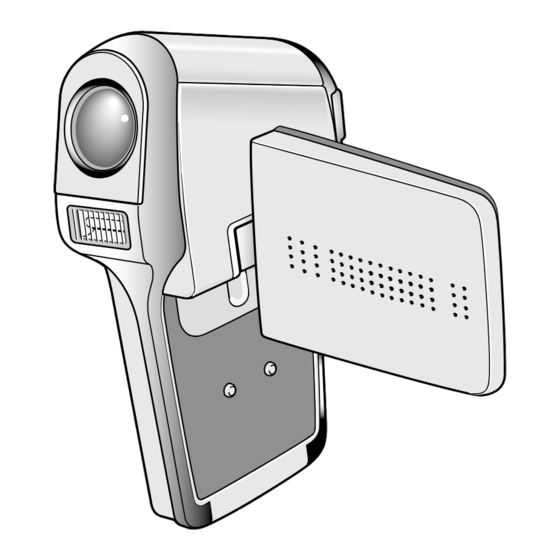
Digital Movie Camera
Contents
1. OUTLINE OF CIRCUIT DESCRIPTION .................... 3
2. DISASSEMBLY ........................................................ 12
3. ELECTRICAL ADJUSTMENT .................................. 16
REGISTRATION ...................................................... 22
5. TROUBLESHOOTING GUIDE ................................. 23
6. PARTS LIST ............................................................. 24
ACCESSORIES ....................................................... 24
PACKING MATERIALS ............................................ 24
CABINET & CHASSIS PARTS 1 ............................. 26
ELECTRICAL PARTS .............................................. 30
CIRCUIT DIAGRAMS &
PRINTED WIRING BOARDS ...................................... C1
WARNING
This product has been manufactured using lead-free solder. Be sure to follow the warning given on page 2 when carrrying out
repair work.
The components designated by a symbol ( ! ) in this schematic diagram designates components whose value are of
special significance to product safety. Should any component designated by a symbol need to be replaced, use only the part
designated in the Parts List. Do not deviate from the resistance, wattage, and voltage ratings shown.
CAUTION : Danger of explosion if battery is incorrectly replaced.
Replace only with the same or equivalent type recommended by the manufacturer.
Discard used batteries according to the manufacturer's instructions.
NOTE : 1. Parts order must contain model number, part number, and description.
2. Substitute parts may be supplied as the service parts.
3. N. S. P. : Not available as service parts.
Design and specification are subject to change without notice.
SX815/U, EX, E, EX2, EX3, EX4
PRODUCT SAFETY NOTICE
FILE NO.
VPC-C6
(Product Code : 168 034 01)
(U.S.A.)
(Canada)
(Korea)
(Taiwan)
VPC-C6EX
(Product Code : 168 034 02)
(China)
(South America)
(Russia)
(Middle East)
(Africa)
(Hong Kong)
(Australia) (General)
VPC-C6E
(Product Code : 168 034 03)
(U.K.)
VPC-C6EXR
(Product Code : 168 034 07)
VPC-C6EXBK
(Product Code : 168 034 08)
VPC-C6EXE
(Product Code : 168 034 13)
(Europe)
REFERENCE No. SM5310643
Advertisement
Table of Contents

Related Manuals for Sanyo VPC-C6


Summary of Contents for Sanyo VPC-C6
-
Page 1: Table Of Contents
FILE NO. SERVICE MANUAL Digital Movie Camera VPC-C6 (Product Code : 168 034 01) (U.S.A.) (Canada) (Korea) (Taiwan) VPC-C6EX (Product Code : 168 034 02) (China) (South America) (Russia) (Middle East) (Africa) (Hong Kong) (Australia) (General) Contents VPC-C6E 1. OUTLINE OF CIRCUIT DESCRIPTION ....3 2. - Page 2 WARNING Do not use solder containing lead. Note: This product has been manufactured using lead-free solder in If replacing existing solder containing lead with lead-free sol- order to help preserve the environment. der in the soldered parts of products that have been manufac- Because of this, be sure to use lead-free solder when carrying tured up until now, remove all of the existing solder at those out repair work, and never use solder containing lead.
-
Page 3: Outline Of Circuit Description
1. OUTLINE OF CIRCUIT DESCRIPTION Pin 1 1-1. CCD CIRCUIT DESCRIPTION 1. IC Configuration The CCD peripheral circuit block basically consists of the fol- lowing ICs. IC903 (MN39830PMJ-A) CCD imager IC901 (AN20112A) V driver IC905 (AD9996BBCZ) CDS, AGC, A/D converter, H driver, vertical TG Pin 13 2. - Page 4 3. Part of IC905 (generation of vertical transfer clock, 4. IC905 (H Driver, CDS, AGC and A/D converter) H Driver) and IC901 (V Driver) IC905 contains the functions of H driver, CDS, AGC and A/D An H driver (part of IC905) and V driver (IC901) are neces- converter.
- Page 5 1-2. CP1, VF1 and TB1 CIRCUIT DESCRIPTION 1. Circuit Description When the TG/SG drives the CCD, picture data passes through 1-1. Digital clamp the A/D and CDS, and is then input to the ASIC as 10-bit The optical black section of the CCD extracts averaged val- data.
- Page 6 4. Lens drive block 5. Video clip recording and playback 4-1. Focus drive 5-1. Recording The focus motor is a stepping motor which is microstep-driven The signals from the camera block are input to the ASIC where by IC951. The 4 MHz clock signal (OSCIN) of the control sig- they are processed, and the image data that is stored in the nals (3-wire serial control (SDATA, SCLK, SENAB), VD) and SDRAM built-in IC101 is input to the IC102 MPEG4 CODEC...
- Page 7 1-3. PWA and VF1 POWER CIRCUIT DESCRIPTION 1-4. Analog 3.4 V Power output 1. Outline (PWA) +3.4 V (A) is output. +3.4 V (A) is output which dropped 3.4 V This is the main power circuit, and is comprised of the follow- by 5V system power output at regulator IC503.
- Page 8 1-4. ST1 STROBE CIRCUIT DESCRIPTION 1. Charging Circuit 2. Light Emission Circuit When UNREG power is supplied to the charge circuit and the When FLCLT signal is input from the ASIC expansion port, CHG signal from microprocessor becomes High (3.3 V), the the stroboscope emits light.
- Page 9 1-5. SYA CIRCUIT DESCRIPTION 1. Configuration and Functions For the overall configuration of the SYA block, refer to the block diagram. The SYA block centers around a 8-bit microprocessor (IC301), and controls camera system condition (mode). The 8-bit microprocessor handles the following functions. 1.
- Page 10 SCAN IN6 Keyscan input 6 Cradle infrared remote control transmission data (asynchronous) input IR_IN Reset input RESET XCIN Clock (32.768 KHz) XCOUT Clock VSS1 Main clock (4MHz) XOUT Main clock VDD1 Backup 3.2 V BATTERY UNREG SY voltage measurement input CHG_DONE Strobo condensor charging completion signal input (H= charging completion) INT_TEMP...
- Page 11 4. Power Supply Control The 8-bit microprocessor controls the power supply for the overall system. The following is a description of how the power supply is turned on and off. When the battery is attached, a regulated 3.2 V voltage is normally input to the 8-bit microprocessor (IC301) by IC303, so that clock counting and key scanning is carried out even when the power switch is turned off, so that the camera can start up again.
-
Page 12: Disassembly
2. DISASSEMBLY 2-1. REMOVAL OF CABINET LEFT, CP1 BOARD AND TB1 BOARD 1. Open the cover battery. 13. Flexible FPC 21. Screw 1.7 x 4 2. Screw 1.7 x 3 14. Connector 22. Assy wire VF1 & TB1 3. Screw 1.7 x 4.5 15. - Page 13 2-2. REMOVAL OF FRONT ASSY, ST1 BOARD AND CA1 BOARD 1. Assy lens 2. Front assy 3. Screw 1.7 x 4 4. Flexible PWB 5. Spacer B 6. Remove the solder. 7. ST1 board 8. Three screws 1.4 x 3.5 9.
- Page 14 2-3. REMOVAL OF CABINET RIGHT, LCD AND VF1 BOARD 1. Button power 10. Four screws 1.4 x 2.5 2. Two screws 1.7 x 2.5 11. Cover LCD back 3. Spring button 12. Assy wire VF1 & TB1 4. Button LCD 13.
- Page 15 2-4. BOARD LOCATION CA1 board VF1 board ST1 board TB1 board CP1 board – 15 –...
-
Page 16: Electrical Adjustment
3. ELECTRICAL ADJUSTMENT 3-4. Setup 3-1. Table for Servicing Tools 1. System requirements Part code Windows 98 or Me or 2000 or XP Ref. No. Name Number IBM R -compatible PC with pentium processor Pattern box (color viewer) VJ8-0190 CD-ROM drive VJ8-0263 Calibration software 3.5-inch high-density diskette drive... - Page 17 3-5. Connecting the camera to the computer 1. Line up the arrow on the cable connector with the notch on the camera's USB port. Insert the connector. 2. Locate a USB port on your computer. 3. Insert the AC adaptor’s cable to DC jack. 4.
- Page 18 3-6. The adjustment item which in necessary in part exchange CCD Black IC501 CCD White Point And White USB storage Factory Lens Oscillation Point Defect Point Defect Language Reset information Cord Frequency Detect Detect Setting Adjustment Setting Adjustment registration Setting Adjustment In Adjustment Adjustment...
- Page 19 Dsc Calibration DscCalDi AWB Result: Focus Result Copy AGC=187,356,525,694,863 STD_AFPOS=1896 3F_AGC=1,2 FOCUS=-4,0,-9,-116 WB=276,516,678 ADJ_PZPOS=15 CHECK=128,128,141 WB_ND=275, 515, 691 CHECK_ND=128, 128, 142 IRIS_GAIN: 52 IRIS_OFFSET: 153 Adjustment value determination is effectuated using the "STD MS=1705,2101,2378,2934 AFPOS" and "FOCUS" values. IRIS=171,156,137,116,109 If FOCUS=focus1, focus2, focus3, focus4 and the adjustment values fulfill the conditions below, they are determined as within IRIS=0 specifications.
- Page 20 5. CCD Black Point And White Point Defect Detect 3-8. Factory Code Setting Adjustment In Lighted 1. Check the "Factory Code" display within the Setting group. 2. For U.S.A., Canada and NTSC general area If "FC_SANYO_U" does not appear, click on the " "...
- Page 21 3-12. Firmware uploading procedure 1. Uploading the firmware should be carried out if the version number (COMPL PWB XX-X) on the replacement circuit board is lower than the version of the distributed firmware. For XX-X, enter the name of the circuit board containing the firmware.
-
Page 22: Usb Storage Information Registration
17.) 2. Double-click on the DscCalDi.exe. 3. Click on the Get button in the USB storage window and check the USB storage data. VID: SANYO PID: C6 Serial: Rev. : 1.00 4. -
Page 23: Troubleshooting Guide
5. TROUBLESHOOTING GUIDE POWER LOSS INOPERTIVE TAKING INOPERATIVE PUSH SHUTTER PUSH THE POWER BUTTON SW FOR A WHILE IC301-30, 31 CHECK UNIT IC301-43 CHECK S3102 (SCAN IN 3, 4) CONTROL PANEL, (SCAN OUT2) PULSE INPUT D3112, D3111 PULSE INPUT IC501-18, 29 CHECK IC101, IC301, IC303-7 5.3 V CHECK TB1, IC955,... -
Page 24: Parts List
CASE SOFT-SX815/J 7001 636 093 8465 CARTON INNER-SX815/EX4, VPC-C6EXE ONLY 636 087 4398 ASSY,CAP LENS-SX719/J, 7001 636 092 3270 CARTON INNER-SX815/U, VPC-C6 ONLY VPC-C6EXBK, VPC-C6EXR 7002 636 078 4659 CUSHION SHEET-SX792/KRNK 636 092 0842 ASSY,CAP LENS-SX815/J, 7003 636 094 2165... - Page 25 6-1. Table of accessories...
-
Page 26: Cabinet & Chassis Parts 1
CABINET AND CHASSIS PARTS 1 LOCATION PARTS NO. DESCRIPTION LOCATION PARTS NO. DESCRIPTION 636 092 0682 CABINET LEFT-SX815/J, 636 092 5113 COMPL PWB,CP-1(F/W) EXCEPT VPC-C6EXR, VPC-C6EXBK 636 094 5791 SPACER_CP1SL_SX815 636 092 9289 CABINET LEFT-SX815/J2, VPC-C6EXR 636 094 5814 SHIELD_TAPE_CP1_SX815 636 092 9470 CABINET LEFT-SX815/J3, VPC-C6EXBK 636 083 0349... - Page 27 CABINET & CHASSIS PARTS 1 SX815/J Parts List1...
-
Page 28: Cabinet & Chassis Parts 2
CABINET AND CHASSIS PARTS 2 LOCATION PARTS NO. DESCRIPTION LOCATION PARTS NO. DESCRIPTION 636 092 9319 ASSY,BUTTON POWER-815/J2, 636 092 0750 COVER JOINT BASE-SX815/J, VPC-C6EXR ONLY EXCEPT VPC-C6EXR, VPC-C6EXBK 636 092 9494 ASSY,BUTTON POWER-815/J3, 636 092 9395 COVER JOINT BASE-SX815/J2, VPC-C6EXBK IONLY VPC-C6EXR ONLY 636 092 0668... - Page 29 CABINET & CHASSIS PARTS 2 SX815/J Parts List2...
-
Page 30: Electrical Parts
ELECTRICAL PARTS Note: 1. Materials of Capacitors and Resistors are abbreviated as follows ; Resistors Capacitors MT-FILM Metallized Film Resistor MT-POLYEST Metallized Polyester Capacitor MT-GLAZE Metallized Glaze Resistor MT-COMPO Metallized Composite Capacitor OXIDE-MT Oxide Metallized Film Resistor TA-SOLID Tantalum Solid Capacitor AL-SOLID Aluminum Solid Capacitor NP-ELECT... - Page 31 LOCATION PARTS NO. DESCRIPTION LOCATION PARTS NO. DESCRIPTION C1020 403 382 3902 CERAMIC 0.1U K 6.3V C5045 403 420 7503 CERAMIC 4.7U K 16V C1021 403 382 3902 CERAMIC 0.1U K 6.3V C5047 403 380 6608 CERAMIC 0.22U K 6.3V C1022 403 382 3902 CERAMIC...
- Page 32 LOCATION PARTS NO. DESCRIPTION LOCATION PARTS NO. DESCRIPTION R1501 401 307 1705 MT-GLAZE 22K JA 1/20W CN141 645 069 7548 SOCKET,CARD(SD) 1(N.S.P) R1502 401 286 4407 MT-GLAZE 240 DC 1/16W CN501 645 072 1823 TERMINAL,3P-SX719 R1503 401 286 4407 MT-GLAZE 240 DC 1/16W R1504 401 302 1700...
- Page 33 LOCATION PARTS NO. DESCRIPTION LOCATION PARTS NO. DESCRIPTION (CONNECTOR) C9722 403 381 8106 CERAMIC 1U K 6.3V CN901 645 077 0111 SOCKET,PWB-PWB 40(N.S.P) (RESISTOR PACKS) (MISCELLANEOUS) RB181 645 061 3722 R-NETWORK 47KX2 1/16W 409 645 1302 IC MN39830PMJ-A (N.S.P.) RB182 645 064 1510 R-NETWORK 2.2KX2 1/16W 636 083 4989...
- Page 34 LOCATION PARTS NO. DESCRIPTION LOCATION PARTS NO. DESCRIPTION (INDUCTORS) (RESISTORS) L1701 645 020 1912 INDUCTOR,240 OHM R5401 401 258 6606 MT-GLAZE 10K DC 1/16W L1702 645 061 7393 INDUCTOR,10U M R5402 401 224 9006 MT-GLAZE 10K JA 1/16W L5102 645 067 2354 INDUCTOR,10U M R5403 401 224 9303...
- Page 35 SANYO Electric Co., Ltd. Osaka, Japan Printed in Japan Nov./’05...
Need help?
Do you have a question about the VPC-C6 and is the answer not in the manual?
Questions and answers