Table of Contents
Advertisement
Quick Links
Advertisement
Table of Contents

Subscribe to Our Youtube Channel
Related Manuals for Systium Technologies 545

Summary of Contents for Systium Technologies 545
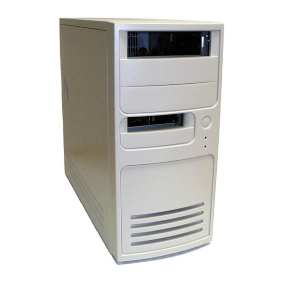
- Page 1 SySTIUM TECHNOLOGIES ® Assembly Guide Model 545...
-
Page 2: Declaration Of The Manufacturer Or Importer
Systium Technologies assumes no responsibility for any errors that may appear in this document. Systium Technologies makes no commitment to update nor to keep current the information contained in this document. No part of this document may be copied or reproduced in any form or by any means without prior written consent of Systium Technologies. - Page 3 To avoid personal injury or damage to your equipment, refer repair The Model 545 supports a number of different motherboards. A or replacement of the power supply to qua 4fied technical number of the assembly step details are different for each personnel only.
-
Page 4: Table Of Contents
CONTENTS side cover upwards and The Model 545 MotherBoard Ready System product contains away from the the following: chassis. Refer to Figure 3. •... -
Page 5: Integration Kit
® System • MODEL 545 SySTIUM TECHNOLOGIES MotherBoard Ready FIGURE 5 for the motherboard being installed for a figure of the correct installation of the motherboard into the I/O shield. Using the mounting screws supplied, mount the motherboard to the chassis. Ensure that the motherboard is fully inserted into the I/O shield while being tightened into place. -
Page 6: Chassis. Refer To Figure 10
® System • MODEL 545 SySTIUM TECHNOLOGIES MotherBoard Ready Installing a I/O Adapter (Optional) FIGURE 9 If an I/O adapter is part of the system configuration the following instructions should be followed. If no I/O adapter is to be installed, then this section can be skipped. -
Page 7: Figure 13
EMI shield can result in EMI leakage that will result in the computer system not meeting the product's EMC compliance. A 5.25" EMI shield is not supplied with the Model 545 and must be ordered separately from Systium. -
Page 8: Figure 16
Configure any jumpers or switch settings required by the peripheral. Refer to the peripheral's user manual for The Model 545 is designed to support mounting of a 5.25” specific instructions. internal peripheral in the lower 5.25” bay. While it is possible to Insert the 3.5”... - Page 9 Install Cover Lock Tab 2. Connect the power cables to the peripherals. The various peripherals are connected as follows: NOTE The Model 545 utilizes a power supply with an Energy Hazard on the ERIPHERAL OCATION OWER ONNECTOR 12V circuit.
- Page 10 ® System • MODEL 545 SySTIUM TECHNOLOGIES MotherBoard Ready Install Side Cover Intel’s Test view. Install any required operating system or application software. NOTE NOTE Before installing the right side cover please check that all cables are The computer must have all the required warning and information connected and no tools, screws or accessories are left inside the lights functioning before shipping to the end user.
- Page 11 The ITOX GCB60-BX motherboard uses the I/O shield supplied with the motherboard. Refer to the main assembly guide for instructions on installing the I/O shield. Installing the Motherboard STANDOFF INSTALLATION No additional standoffs are required. INSTALLATION OF FRONT PANEL CONNECTORS Copyright © 2007, Systium Technologies, LLC PN: 91260-00...
- Page 12 S3000AH ASSEMBLY INSTRUCTIONS I/O Shield FIGURE 3 The Intel S3000AH motherboard uses the Intel I/O shield supplied with the motherboard. Refer to the main assembly guide for instructions on installing the I/O shield. Installing the Motherboard STANDOFF INSTALLATION The S3000AH does not require installation of the brass stand-offs included in the integration kit.
- Page 13 • MO D E L 5 4 5 SySTIUM TECHNOLOGIES OTHER OARD EADY YSTEM RADISYS KP915GV ASSEMBLY INSTRUCTIONS I/O Shield 3. Turn the motherboard over while holding the support bracket in place. Place the new heat sink mount on the motherboard. Attach the heatsink using the 4 built-in screws.
- Page 14 Install one brass standoff, included in the chassis integration kit, in the location shown in the figure below. MOTHERBOARD INSTALLATION Be careful installing the motherboard making sure none of the I/O shield tabs get bent or damaged. Copyright © 2003, Systium Technologies, LLC PN: 91136-00...
- Page 15 • MO D E L 5 4 5 SySTIUM TECHNOLOGIES OTHER OARD EADY YSTEM BCM BC945G ASSEMBLY INSTRUCTIONS I/O Shield 3. Turn the motherboard over while holding the support bracket in place. Place the new heat sink mount on the motherboard. Attach the heatsink using the 4 built-in screws.
- Page 16 • MO D E L 5 4 5 SySTIUM TECHNOLOGIES OTHER OARD EADY YSTEM BCM RX945G ASSEMBLY INSTRUCTIONS I/O Shield 3. Turn the motherboard over while holding the support bracket in place. Place the new heat sink mount on the motherboard. Attach the heatsink using the 4 built-in screws.
- Page 17 • MO D E L 5 4 5 SySTIUM TECHNOLOGIES OTHER OARD EADY YSTEM BCM IN915GVE ASSEMBLY INSTRUCTIONS I/O Shield 3. Turn the motherboard over while holding the support bracket in place. Place the new heat sink mount on the motherboard. Attach the heatsink using the 4 built-in screws.
- Page 18 SySTIUM TECHNOLOGIES • MODEL 545 OTHER OARD EAD Y YSTEM DG33FB ASSEMBLY INSTRUCTIONS I/O Shield 3. Turn the motherboard over while holding the support bracket in place. Place the new heat sink mount on the motherboard. Attach the heatsink using the 4 built-in screws. See Figure 3 The Intel DG33FB motherboard uses the Intel I/O shield supplied with the BOX motherboard.
- Page 19 SySTIUM TECHNOLOGIES • MO D E L 5 4 5 OTHER OARD EADY YSTEM RADISYS LR915G/BY915GV ASSEMBLY INSTRUCTIONS 3. Turn the motherboard over while holding the support bracket in I/O Shield place. Place the new heat sink mount on the motherboard. Attach the heatsink using the 4 built-in screws.
- Page 20 SySTIUM TECHNOLOGIES • MO D E L 5 4 5 OTHER OARD EADY YSTEM RADISYS RB945G ASSEMBLY INSTRUCTIONS 3. Turn the motherboard over while holding the support bracket in I/O Shield place. Place the new heat sink mount on the motherboard. Attach the heatsink using the 4 built-in screws.
- Page 21 Install two brass standoffs, included in the chassis integration kit, in the locations shown in the figure below. MOTHERBOARD INSTALLATION Be careful installing the motherboard making sure none of the I/O shield tabs get bent or damaged. Copyright © 2003, Systium Technologies, LLC PN: 91134-00...
- Page 22 The BCM BC35Q motherboard uses the I/O shield rear panel supplied with the motherboard. 115V AC or 230V AC Installing the Motherboard The BCM BC35Q motherboard is installed as described in the Model 545 Assembly Guide. No extra steps are required. Installation of Front Panel Connectors Connect Peripheral Cables Refer to the Model 545 Assembly Guide for the suggested peripheral cable routing.
- Page 23 System • MODEL 545 ® SySTIUM TECHNOLOGIES MotherBoard Ready INTEL DG43NB ASSEMBLY INSTRUCTIONS I/O Shield Turn the motherboard over while holding the support bracket in place. Place the new heat sink mount on the motherboard. Attach the heat sink using the 4 built-in The Intel DG43NB uses the Intel I/O shield supplied with the screws.
- Page 24 The assembled configuration maximum power load cannot exceed the safety certification configuration maximum power load. The power supply’s output ratings are higher than the Model 545 system safety certification ratings. Customer configurations should be checked to ensure that the system’s safety certification loads are not exceeded.
- Page 25 NOTE Use Only for Intended Applications This product was evaluated as Information Technology Equipment (ITE) that may be installed in offices, homes and similar locations. The use of this product for other Product Safety Categories or Environments other than ITE may require further evaluation. Examples of other Product Safety Categories are Medical Instrumentation or Control and Test Equipment.
Need help?
Do you have a question about the 545 and is the answer not in the manual?
Questions and answers