Table of Contents
Advertisement
Advertisement
Table of Contents

Related Manuals for Mackie DC16


Summary of Contents for Mackie DC16
- Page 1 OWNE R’ S M ANU AL OWN E R’ S MAN U AL...
-
Page 2: Important Safety Instructions
DC16 Owner’s Manual Important Safety Instructions 1. Read these instructions. 18. NOTE: This equipment has been tested and found to comply with the limits for a Class B digital device, pursuant to part 15 of the FCC Rules. These limits are designed to provide 2. -
Page 3: Table Of Contents
Dante ..............................11 Why Use Dante? ............................11 Dante Routing ............................11 Chapter 4 : DC16 Front and Rear Panels ..................17 Front Panel Introduction........................... 17 Phones Jacks ..........................17 Rear Panel Introduction ..........................18 Talkback Mic Input ........................18 1/8"... - Page 4 DC16 Owner’s Manual Channel Screens Overview ........................25 Channel Displays and Encoders ....................25 Channel Editing Page Buttons ....................26 Banking Group Selector ..........................26 BANK Buttons ..........................26 CHANNEL Buttons ........................26 Groups Selector ............................27 VIEW Group Button ........................27 MUTE Group Button .........................
- Page 5 Examples of Follow Mode ....................66 Appendix A : Hookup Diagram ....................74 Appendix B : Technical Information ................... 75 Specifications ............................. 75 DC16 Dimensional Drawings ........................79 Appendix C : Service Information ....................81 Warranty Statement / GPL Statement ..................83...
-
Page 6: Chapter 1 : Welcome
Instead of one massive document containing detailed information about the hardware and software, we have divided them into separate manuals. Simply decide if you need assistance with the DC16 control surface hardware or Master Fader iOS control app and dive on in. The water here is warm and crystal clear. -
Page 7: Chapter 2 : Getting Started
5. Turn the DL32R on first and the DC16 on second. [Technically the DC16 will still be able to discover the DL32R if the DC16 is powered on first, but you might be required to refresh the mixer list the DC16 received.] Follow the on-screen instructions of the DC16 –... - Page 8 DL32R Mixer list Initializing... Select Do it! Exit (C) – We’ll assume here that you will only be using a single DC16 at this time. Therefore, push the encoder in to select the FOH slot. DC16 Select DL32R connection Initializing...
- Page 9 6. Turn the powered speakers (or amplifiers) on. 7. Connect an iPad to the iPad Control Port (located on the rear panel of DC16), launch the Master Fader app and connect to the DL32R / DC16 (as explained in the Master Fader Reference Guide ‘Devices’ section).
-
Page 10: Chapter 3 : A Closer Look At Slots And Dante
DL32R is on the network connected to the Wi-Fi port. We already set up the FOH DC16, but need to select the MON slot for the MON DC16 as described on page 70. Additionally, you will need to set up the DC16 Slot’s Follow Mode [Tools > Controllers > DC16 Slot] on each iPad. -
Page 11: Dante
Ethernet switch in many situations. Here, you should use a shielded network cable that is CAT5E (or better) to connect DC16 to the DL32R. This allows for control, monitoring, talkback and more. Additionally, the Dante ports may also be used to connect to other Dante-enabled audio networks. - Page 12 DL32R and DC16. ” In short, you’re setting up a monitor mix FOR DC16 FROM DL32R. That is, what goes TO the DC16 headphone and monitor outputs is a mirror image of the DL32R headphones and monitor outputs. The L/R FROM DL32R TO DC16 feeds the iPad record input, the record input being a stereo L/R mix recording.
- Page 13 DC16 Owner’s Manual The same exact thing shown on the previous page is outlined below now. Instead of the signal flow, though, it’s the Dante routing. DL32R OUT to DC16 IN DC16 OUT to DL32R IN...
- Page 14 DC16 Owner’s Manual Now let’s take a look at Master Fader’s I/O Patch. For reference, the right-hand side of the signal flow – the DL32R side – may be seen below-left. As stated previously, the first thing routed in Master Fader’s I/O Patch is Input A (below-right).
- Page 15 DC16 Owner’s Manual Other Dante Routing Perhaps you recall that Dante 1-29 had no default patching. That’s because they are available for a variety of other purposes. You have multiple controllable options for routing and where they’re routed. We have addressed three possible ways to record shows, including: •...
- Page 16 DC16 Owner’s Manual The second step is to set up Dante routing via Master Fader [Tools > I/O Patch > Dante]. We already set up Dante with a 1-to-1 setup, so we need to do the same in Master Fader. See below.
-
Page 17: Chapter 4 : Dc16 Front And Rear Panels
Front Panel Introduction From left to right, the front panel of each DC16 is outfitted with a phones jack and...that’s it! Let’s take a look at the phones jack then move on to the rear panel before it’s too late. -
Page 18: Rear Panel Introduction
Rear Panel Introduction From left to right, the rear panel of each DC16 is outfitted with a talkback mic input jack, an 1/8" stereo input jack, 1/4" L/R monitor output jacks, a 1/4" footswitch jack, two Dante I/O jacks, a force update button, a network connector for Wi-Fi control, three USB ports for iPad control and charging, a power connector and power switch and last but not least...a 4-pin input jack for a lamp. -
Page 19: 1/4" Footswitch Jack
Ethernet switch in many situations. Here, you should use a shielded network cable that is CAT5E (or better) to connect DC16 to the DL32R. This allows for control, monitoring, talkback and more. Additionally, the Dante ports may also be used to connect to other Dante-enabled audio networks. -
Page 20: Force Update Button
DC16 and Master Fader app do a great job at letting you know when either (or both) the software and firmware need updating, but this button here forces a complete firmware update if the need ever arrives. -
Page 21: Power Connector
Power Switch Push to lock, pull (on outlined area) Press the top of this rocker switch in to turn the DC16 on and press the bottom to unlock and remove. of this switch to turn it off. As a general guide, the Wi-Fi router should be turned on first,... -
Page 22: Chapter 5 : Dc16 Top Panel
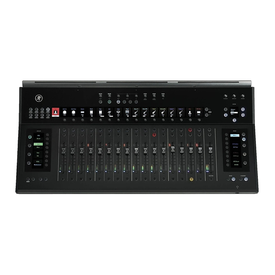
Top Panel Introduction From top to bottom and left to right, the top panel of each DC16 is outfitted with a bunch of knobs, switches, faders, screens, encoders and more. So much more, in fact, that we will call out and describe each one... but not here... -
Page 23: Input Channels / Master Channel
The selected input or output will be presented in the Selected Channel display in the upper-left corner of DC16 (next to the channel editing buttons), regardless of what bank of channels or output is currently viewed in the remaining 16 ID displays. -
Page 24: Gain Reduction Leds
DC16 Owner’s Manual • Gain Reduction LEDs The input gain reduction LEDs display the channel gain reduction from the gate and compressor, while the output gain reduction LEDs display the amount of gain reduction applied to the output by the compressor / limiter. Output channels do not contain gates. -
Page 25: Channel Screens Overview
DC16 Owner’s Manual Channel Screens Overview Lying horizontally above the fader strips are 17 channel displays and two Channel Editing Page buttons. The channel display on the far left is the selected channel display and does not have an encoder below it;... -
Page 26: Channel Editing
Wedges Banking Group Selector In the lower right corner of DC16 (below the Mix Selector) are four buttons that make up the Banking Group. As seen below, two buttons are for switching banks and two are for switching channels. In-ears Bank / Channel •... -
Page 27: Groups Selector
DC16 Owner’s Manual Groups Selector The groups selector section – appropriately named “GROUPS” – is located on the left-hand side of DC16 just to the left of the faders. Here is where channel settings, view groups, mute groups, user-assignable controls, context-sensitive editing controls and more are displayed and edited. - Page 28 Additionally, channels may be assigned (and unassigned) to view groups simply by utilizing the assign modifier button. More details in the “Modifiers” section on pages 57-59. While view groups may be displayed and selected via DC16, the names will still need to be created using Master Fader.
-
Page 29: Mute Group Button
DC16 Owner’s Manual • MUTE Group Button Mute groups allow you to quickly mute (and unmute) multiple channels and/or outputs. There are a multitude of possibilities in which to assign and enable mute groups: productions featuring a rotating cast of musicians, theater productions, a house of worship and more. It is also great for muting all inputs during song breaks or in-between sets. -
Page 30: User Button - Nyi
(and unassigned) to mute groups simply by utilizing the assign modifier button. More details in the “Modifiers” section. NONE While mute groups may be displayed and selected via DC16, the names will Break still need to be created using Master Fader. Intro... -
Page 31: Mix Selector
DC16 Owner’s Manual Mix Selector The mix selector section – appropriately named “MIXES” – is located on the right-hand side of DC16 just to the right of the faders. This is the place to select between output mixes, cycle through the displayed outputs, display output masters, clear all engaged solos and engage the talkback mic. -
Page 32: Page Buttons
LED status: The arrow button LEDs are always illuminated when they are available for use. If the button LEDs are not illuminated, then the DC16 is at the very top or very bottom of the mixes list (or in masters mode in which case neither arrow button LED will illuminate). - Page 33 As such, the master fader now controls the level of the selected output. It’s the highlighted A11-A12 in this example. Master Fader DC16: A7 – A14 [Page 2] Default Default...
- Page 34 As such, the master fader now controls the level of the selected output. It’s the highlighted Rev1 Plate in this example. Master Fader DC16: FX [Page 3] Default Default...
- Page 35 When a sub is selected, only the input channels that are associated with the selected sub are displayed. If no channels have been assigned to a sub – Sub5 and Sub6 in this example – then no channels will be displayed. Master Fader DC16: Subs [Page 4] Default Default Customized...
- Page 36 When a VCA is selected, only the input channels that are controlled by the selected VCA are displayed. If no channels have been assigned to a VCA – VCA4-VCA6 in this example – then no channels will be displayed. Master Fader DC16: VCAs [Page 5] Default Default Customized...
- Page 37 When a matrix is selected, the DC16 will display all subgroups, LR and auxes. The LR and auxes mix selector LEDs are displayed in the color of the selected matrix [default is white], but the subs will be displayed in the color of the sub [default is blue].
-
Page 38: Mast(Er) Button
Also, unlike the mix selector, the masters list can’t be “customized”. The DC16’s masters selector (below left, examples A and B) nearly mirrors that of Master Fader’s masters selector (below right). -
Page 39: Clear Solo Button
• CLEAR SOLO Button In-ears The Clear Solo button’s LED on DC16 illuminates orange to serve as a reminder that a soloed channel exists somewhere, be it an input or output. This is especially useful when an output is soloed and you switch to adjust a different channel on a different output. -
Page 40: Channel Editing
DC16 Owner’s Manual Channel Editing The channel editing buttons are conveniently located in the upper-left corner of the DC16 to the left of the channel IDs and above the groups selector section. The channel editing buttons give you fast access to all of the channel processing. These buttons – in conjunction with the channel displays and editing encoders –... -
Page 41: All Channel Editing
The gain levels may then be changed by rotating the encoders below the channel displays. A visual representation may be seen on the DC16 channel displays and the input routing screens on Master Fader. -
Page 42: Hpf / Lpf Button
A visual representation may be seen on the DC16 channel displays and the channel’s EQ screens on Master Fader. The HPF ranges from Off to 700 Hz (inputs) and Off to 20 kHz (outputs). The incremental adjustments are dependent on if the selected EQ is modern or vintage. -
Page 43: Send / Delay Button
The channel editing page button LEDs are always illuminated when they are available for use. If one of these button LEDs is not illuminated, then the DC16 is at the very top [Aux 1] or very bottom [Dly] of the sends list. There will always be a minimum of one channel editing page button LED illuminated when the channel sends are displayed. -
Page 44: Pan / User [Nyi] Button
This button selects the pan and balance of all inputs and outputs. The pan / balance may then be changed by rotating the encoders below the channel displays. A visual representation may be seen at the bottom of the DC16 channel displays and on the pan screen of Master Fader. -
Page 45: Eq / Assign [Nyi] Button
The EQ parameters may then be changed by rotating and/or pushing the encoders below the channel displays. A visual representation may be seen on the DC16 channel displays and the EQ screen on Master Fader. -
Page 46: Geq / Sends Button
The GEQ parameters may then be changed by rotating the encoders below the channel displays. A visual representation may be seen on the DC16 channel displays and the GEQ screen on Master Fader. The GEQ gain ranges from –12 dB to +12 dB and adjusts in ±1 dB increments. The frequency bands are listed near the bottom of each channel display, just above gain range bar. - Page 47 The sends levels may then be changed by rotating the encoders below the channel displays. A visual representation may be seen on the DC16 channel displays and input routing view on Master Fader. The sends ranges from Off to +10 dB.
-
Page 48: Dyn(Amics) / Setup Button
The gate and comp parameters may then be changed by rotating [levels] and/or pushing the encoders [on / off ] below the channel displays. A visual representation may be seen on the DC16 channel displays and the dynamics screen on Master Fader. -
Page 49: Fx / Trans(Port) [Nyi] Button
Master Fader app. The FX parameters may then be changed by rotating the encoders below the channel displays. A visual representation may be seen on the DC16 channel displays and the FX screen on Master Fader. Kick... -
Page 50: Fat Channel
Fat Channel The Fat Channel is conveniently located dead center of the DC16 above the channel IDs and in front of the center iPad. In addition to the fader controls, the Fat Channel is likely where you will spend the majority of time. -
Page 51: Trim Encoder (Alt + Gain)
DC16 Owner’s Manual • TRIM Encoder (ALT + GAIN) This encoder adjusts the level of the digital trim of the selected input. Trim is a digital level control at the top of the channel’s processing. It affects all input sources to the channel whether analog or digital and is used for adding or removing level to a channel before any of the channel processing. -
Page 52: Four-Band Parametric Eq Buttons And Encoders [Gain, Freq, Q]
DC16 Owner’s Manual • Four-band Parametric EQ Buttons and Encoders [GAIN, FREQ, Q] The four “BAND” buttons allow you to select which EQ band you want to update of the selected input or output. The currently selected band button LED illuminates white when engaged. -
Page 53: Comp Ratio Encoder (Alt + Comp Thresh)
DC16 Owner’s Manual • COMP RATIO Encoder (ALT + COMP THRESH) This encoder adjusts the comp ratio of the selected input or output. The ratio is changed by rotating the encoder and the comp may be turned on [green] or off [white] by pushing the encoder. Ratio sets the amount of gain reduction applied as the signal exceeds the threshold level. -
Page 54: Snapshot Control
Snapshot Control The snapshot control section – “SHOW” – is located in the upper-right corner of DC16 just below the three analog controls and above the mix selector – “MIXES”. Here you are able to easily view, select, recall and store snapshots. -
Page 55: Recall Button
After all, a new snapshot cannot be recalled, only stored! As with Master Fader, recalling snapshot “0 - Default” on DC16 will set the Master Fader to its default (which – for all intents and purposes – is a zeroed out board). Snapshot “0 - Default”... -
Page 56: Analog Controls
DC16 Owner’s Manual Analog Controls These three analog controls (located in the upper-right corner of DC16) allow you to raise and lower the talkback, monitor and headphones levels. Because these are analog controls, they are NOT recallable. Analog Controls • TALKBACK Knob This knob controls the input level of the talkback mic with the gain ranging from a low of off (–∞) -
Page 57: Modifiers
DC16 Owner’s Manual Modifiers The modifiers section is located on the left-hand side of DC16 just below the groups section. It consists of four buttons that are used to modify the functionality of other controls. These buttons are simply modifiers and won’t work on their own. -
Page 58: Asgn Button
DC16 Owner’s Manual • ASGN Button This button is used in conjunction with other buttons to adjust input and output assignments. There’s a lot of info here, so please pay attention! The button’s LED illuminates solid red when pressed and held, but another button must be pressed in order to enter what’s called “Assignment Mode”. -
Page 59: Lock Button - Nyi
DC16 Owner’s Manual • ASGN + View Group – Pressing and holding the ASGN button while pressing one of the [Groups Selector] view groups buttons [view group A-F] puts the console into assignment Assign Mode: mode for that view group. The SEL button LEDs of channels that are already assigned to the View Group E chosen view group will flash, indicating that they are assigned to that view group. -
Page 60: Smart Bridge
Also of note is that the iPads look and perform as if they are integrated with DC16. What sets us apart from the “other” guys, though, is that they are integrated...but not permanently. This means that each iPad may be removed for wireless mixing. -
Page 61: Ipad Setup
The first step here is to set up the iPads correctly. As seen in the image on the previous page, the main iPad is located in the center position (connected to the CONTROL USB port on the rear panel of DC16). -
Page 62: Dc16 Slot
DC16 Owner’s Manual DC16 Slot: The DC16 Slot pull-down menu is where you select which DC16 you want the iPad to follow. In most cases this will either be FOH or MON, but there are two additional choices – slot 3 and slot 4. -
Page 63: Follow Mode
DC16 Owner’s Manual • Follow Mode As mentioned earlier, Follow Mode allows you to customize each iPad on the Smart Bridge to behave automatically. Simply configure and integrate the setup you desire, then start mixing! As seen in the screen shot below, there are five Follow Mode selections to choose from, including:... -
Page 64: Fixed View
DC16 Owner’s Manual Fixed View: Like the Current and History Follow Modes, Fixed View is somewhat self-explanatory. iPads that are set to Fixed Mode will stay on the view you desire regardless of the Follow Mode setting on the other iPads. While the view constantly changes on iPads set to Current and History Follow Modes, the view on iPads set to Fixed View won’t change at all...until you... -
Page 65: Surface To Wireless Mixing
DC16 Owner’s Manual The fourth pull-down menu – Overview Selects Current – has two options: On [default] or Off. What this means is that when an iPad is displaying Overview, you can select whether or not any iPads following the current channel go to the selected input(s) or output(s) when touched on the Overview screen. -
Page 66: Examples Of Follow Mode
Once the channel is changed on the DC16 surface on on iPad A, it becomes history. This history, though, is still readily available, now on iPad B since it’s set to 1st History. - Page 67 (important) channel’s Channel View. A lead vocalist’s FX channel, for example. With this configuration, you can touch a channel on the overview and it will be selected on the DC16 surface and iPad A. One Follow Mode I like to use is this: iPad A –...
- Page 68 DC16 Owner’s Manual Having said that, the Product Manager and our road warriors prefer a similar setup, but ever-so-slightly different. See below: iPad A – 1st History Selected Channel iPad B – Current Selected Channel iPad C – Fixed View...
- Page 69 When a different channel is selected (whether by pushing a SEL button on DC16 or swiping left or right on Master Fader), all three iPads will display the same view as before and all on the same channel...the selected channel! This way you have instant access to that channel’s three main Channel Views.
- Page 70 DL32R for the associated slot. So if you change DC16s, the slot retains the settings and the new DC16 will come up just like the old one. More about slots below. The DYN button’s LED illuminates white when engaged.
- Page 71 High [Default] Sun – NYI – The “Sun” setting is not yet implemented, but will add a high contrast mode so the screen brightness is even more legible when the DC16 is used in direct sunlight at outdoor venues. Button Brightness:...
- Page 72 The default [Off ] just means that there is no auto return to SELECTED channel editing. DC16 follows your every move and stays where you leave it. Second, any of the available ALL channel editing selections may be chosen (including most ALT + selections).
- Page 73 About: This is the place to view the settings of this particular DC16. Press the encoder to display similar settings as seen below. Press the “Cancel” encoder when you are finished with this view.
-
Page 74: Appendix A : Hookup Diagram
* Ethernet cable from the router to the Wi-Fi Control jack. * Lightning cables from the Control and Charging jacks connected to the three iPads. * Ethernet cable from the Dante jack on DC16 to the Dante jack on the DL32R. DL32R Front Panel: * 1-24 XLR cables connected to inputs 1-24. -
Page 75: Appendix B : Technical Information
DC16 Owner’s Manual Appendix B : Technical Information Specifications General Digital Sample Rate: .........................................48 kHz A/D/A Bit Depth: ......................................24-bit 0 dBFS Reference: ....................................+22 dBu Frequency Response All inputs to all outputs: ............................ ±0, –1 dB, 20 Hz to 20 kHz Stereo Input Connector: .................................... - Page 76 DC16 Owner’s Manual Specifications Continued... Analog Monitor Outputs L/R Connectors: ..............................1/4" TRS Impedance Balanced [Supports balanced / unbalanced operation] Output Impedance: ................................240 Balanced, Unbalanced Max Output Level: ....................................+21 dBu Analog Headphone Out Connector: ....................................1/4" TRS Stereo Max Output Level: ................................+18 dBu into 600 +19.5 dBu max into 100 k...
- Page 77 DC16 Owner’s Manual Specifications Continued... Dante Connection: ..............................2x etherCon Gigabit Ethernet Sample Rate: .........................................48 kHz Bit Depth: ........................................24-bit Transmit / Receive Channels: ..................................4 / 4 Supports Dante Switch modes Configuration via Dante Controller Supported Devices iOS Version Requirement: ....................For optimal performance, we suggest using the latest iOS version [iOS 8.0 minimum]...
- Page 78 ©2016 LOUD Technologies Inc. All rights reserved. Apple, iPad, iPhone and iPod touch are trademarks of Apple Inc., registered in the U.S. and other countries. All other marks are Registered Trademarks, or Trademarks, of LOUD Technologies in the United States and other countries. DC16 and DL32R Patent Pending.
-
Page 79: Dc16 Dimensional Drawings
DC16 Owner’s Manual DC16 Dimensional Drawings... - Page 80 DC16 Owner’s Manual DC16 Dimensional Drawings Continued...
-
Page 81: Appendix C : Service Information
Appendix C : Service Information Troubleshooting If you think your DC16 has a problem, please check out the following troubleshooting tips and do your best to confirm the problem. Visit the Support section of our website (www.mackie.com/support) to get some ideas or contact our technical support heroes. You may find the answer to the problem without having to send your DC16 away. - Page 82 Did you connect the Ethernet cable to the correct port on the router? Be sure to use the LAN port and not the WAN port. • Did you connect and then power on the Wi-Fi router BEFORE turning on the DC16 / DL32R? • Leave Master Fader and then return by pressing the Home button on the iPad.
-
Page 83: Warranty Statement / Gpl Statement
The Product Warranty will not extend to anyone other than the original purchaser of the product (hereinafter, “Customer,” “you” or “your”). For products purchased outside the U.S. or Canada, please visit www.mackie.com/warranty to find contact information for your local distributor, and information on any warranty coverage provided by the distributor in your local market.
Need help?
Do you have a question about the DC16 and is the answer not in the manual?
Questions and answers