DSC PC6010 System Manual
Hide thumbs
Also See for PC6010:
- Programming manual (52 pages) ,
- Quick reference manual (32 pages) ,
- Maintenance manual (32 pages)
Table of Contents
Advertisement
Advertisement
Table of Contents

Related Manuals for DSC PC6010


Summary of Contents for DSC PC6010
- Page 1 System Manual • W A R N I N G • This manual contains information on limitations regarding product use and function and information on the limitations as to liability of the manufacturer. The entire manual should be carefully read. ®...
-
Page 2: Table Of Contents
Contents Section 1: Introduction ..........1 Section 5: Programming the PC6010 ......14 Introduction to PC6010 ........1 Introduction to Programming ......14 Using PC6010 Manuals ........1 Programming Using Hotkey Numbers ... 14 Programming Decimal Data ......14 Section 2: System Overview .......... 2 Programming Hexadecimal Data .... -
Page 3: Section 1: Introduction
“Downloading”). each programming section. • Be sure to record all your system programming in the Programming Worksheets. • If you will be adding modules to your PC6010 system, please read the Installation Instructions that come with each module. User Manuals Two end-user manuals come with the PC6010 system: •... -
Page 4: Section 2: System Overview
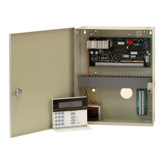
• Separate or shared zones from other areas Maximum System Capabilities • Individual keypads per area • Control Unit - 1 PC6010 Main Board • Individual access codes for each area • Up to 256 zones • Individual outputs programmable per area... -
Page 5: Module Specifications
PC6400 Serial (Printer) Module • True RS-232 technology 2 Enclosures • Handshake software switches • PC4005C cabinet: PC6010 and two modules • DTR Protocol • PC4003C cabinet: 2- PC6108A modules, 1 - PC6204 • Baud rate: 4800 module, 1- PC6216 module, or 1 PC6400 module •... - Page 6 PC6501 Remote Keypad Battery • 12V 7.0Ah recommended rechargeable gel-cell • Connects to control panel via 4-wire Ebus • Alphanumeric liquid crystal display Transformer • Built-in piezoelectric buzzer • 16.5 V , 40VA • Full annunciation of zones and system status Operating Temperature •...
-
Page 7: Section 3: Installation And Wiring
Section 3: Installation and Wiring Planning the System Terminal Descriptions For a fast and efficient installation of the PC6010, you should The following terminals appear on the PC6010 Control Panel: create an installation plan. Terminals Description As a minimum, use the following checklist to ensure that all of... -
Page 8: Current Ratings - Alarm Control Panel And Modules
Use the data below to ensure that the available current is not exceeded. Reader 1 PC6010 Control Panel Current Calculation At least 100mA must be reserved for the Ebus. To calculate the Reader 2 amount of current required, complete the following chart:... -
Page 9: Ebus Operation And Wiring
Ebus Operation and Wiring The following chart indicates the total Ebus wire allowed depending on the capacitance rating of the wire used: The Ebus is used by the control panel and the modules to communicate with each other. The four Ebus terminals of the Wire Capacitance per TOTAL Ebus Wire main panel must be connected to the four Ebus terminals or... -
Page 10: Backbone Operation And Wiring
NOTE: New versions of the PC6204 power supply module have • Four wire runs at 1000'/305m each a jumper marked ‘J1’. Ensure that this jumper is configured for • Six wire runs at 666'/203m each “Ebus Relay.” Otherwise, the power reset function will not •... -
Page 11: Specialized Zone Wiring
These zones are listed below. For information via the cellular network. If the LINKS detects an incoming call, it regarding the various zone types, please see the PC6010 will activate an output that can be used to violate this zone type. -
Page 12: Wiring Powered Devices (Aux, Saux+)
1. Select a dry location close to an unswitched AC source, a round connection and a telephone connection for mounting the Main Control Cabinet. 2. Remove the PC6010 printed circuit board, mounting hardware, and keypad from the cardboard retainer inside the large cabinet. -
Page 13: Applying Power (Ac And Battery)
The PC6010 monitors the presence of AC power on all modules 2. Determine the current that will be drawn when the panel is on the system. The Power light on the keypad will always be on in alarm. -
Page 14: Section 4: Module Enrollment
AC transformer (see section 3.16). All LCD 1. Enter installer’s programming by pressing [*] [8] [Installer’s keypads will display the message “PC6501 DSC Ltd.” Code]. NOTE: Make sure all power to the system is OFF when connecting 2. -
Page 15: Enrolling Pc6442 And Pc6443 Modules
Enrolling PC6442 and PC6443 Deleting Modules Modules Sometimes, a module must be deleted from the system. This could be when zone expanders are enrolled out of sequence, a Before you can enroll any PC644X module, you must program keypad is assigned to the wrong area, or if a module is defective. the Originator ID to be [01]. -
Page 16: Section 5: Programming The Pc6010
Programming From a Keypad Enter the 6-digit Area 2 ID code. The display returns to the To program the PC6010 using the menu system, you must have message “Area ID Code”. installed and enrolled at least one keypad. See section 4 for more information. -
Page 17: Programming Hexadecimal Data
If you press the [#] key, only the data that you entered will be 3. When the desired letter is displayed, press [*] again. changed. All remaining programming data will be left You can also enter Hex digits by pressing [*], followed by the unchanged. -
Page 18: Section 6: Keypad Operation And User Types
Section 6: Keypad Operation and User Types Introduction User Types The PC6501 liquid crystal display The PC6010 system can have up to 1000 users programmed. (LCD) keypad guides users through Users can be assigned to one of four user types: Basic, each operation with easy-to- Advanced, Supervisor and Master users. -
Page 19: Warning - Security Reduced" Messages
Master and Supervisor users can select the level of (non-boosted) Daylight Savings and Standard Time programming sections. See backlighting in the Keypad Setup section of the user menu. System Times in the PC6010 Programming Manual for more information. If the system is connected to Alarm Presentation Software over... -
Page 20: Section 7: System Operation And Programming
Access Control System toggle options, keypad lockout options, system times, If you connect one or more PC6820 modules to the PC6010 and the arm/disarm mask for areas are in the System Options system, you can program the system to control access to up to section. -
Page 21: Zone Operation
Arming with Zones Open If there are zones open when an area is armed by keyswitch, or The status of the PC6010 system can be monitored over telephone lines, or over a dedicated “Backbone” network using automatic arming, the open zones will be force armed. The force the PC6442, or PC6443 modules. -
Page 22: Section 8: Printer Setup
• Serial interface then look similar to Sample 3. • Baud rate = 4800 If the printer is off line or disconnected, the PC6010 keeps new • Parity = None events in memory until the printer is ready to print. -
Page 23: Section 9: Downloading
2. Enable PC-LINK in the Modem Configuration section of the DLS-3 software. The software will display “PC-LINK Active” You can set up the downloading so that the PC6010 will call the in the Status Bar of the Communications window. computer, or have the computer call the control panel. -
Page 24: Section 10: Diagnostics, Restoring Defaults, Viewing Faults
3. Exit user programming and then enter Installer’s PC6443), select “Backbone Modules”. Programming ([*][8][Installer’s Code]). 4. If there are no problems, the keypad will display “PC6010 4. Select “Diagnostics”, and then “Factory Default”. System No Faults Found.” 5. The keypad displays the message “Power System Down and If there is a problem, the keypad will display “Error... - Page 25 Fault ODS. 6204 AC A PC6204 relay output module loses incoming AC Backbone Comm The PC6010 has lost communications with the Trouble power (keypad will be silent). Fault PC6442 and/or PC6443. 6204 AUX The Auxiliary supply on any PC6204 relay module is Trouble overloaded.
-
Page 27: Limited Warranty
LIMITED WARRANTY WARNING Please Read Carefully Note to Installers Digital Security Controls Ltd. warrants the original purchaser that for a period of twelve months from the date of purchase, the product shall be free of defects in materials and This warning contains vital information. As the only individual in contact with system users, it is your responsibility to bring each item in this warning to the attention of the users of this system. - Page 28 ©2000 Digital Security Controls Ltd. Toronto, Canada www.dsc.com Printed in Canada 29005176 R001...
Need help?
Do you have a question about the PC6010 and is the answer not in the manual?
Questions and answers