
Related Manuals for Samsung 741MP


Summary of Contents for Samsung 741MP
-
Page 1: Service Manual
LCD-Monitor Chassis LS17DOA LS19DOA Model 741MP 941MP SERVICE Manual LCD Monitor Fashion Feature - All - in - One Chip... - Page 2 Copyright Trademarks Samsung is the registered trademark of Samsung ©2006 by Samsung Electronics Co., Ltd. Electronics Co., Ltd. All rights reserved. LS17DOA, LS19DOA and MacMaster Cable Adapter This manual may not, in whole or in part, be copied, are trademarks of Samsung Electronics Co., Ltd.
-
Page 3: Table Of Contents
Contents . Precautions ………………………………………………………………………………………………………………………………………1 1-1. Safety Precautions ………………………………………………………………………………………………………………………1-1 1-2. Servicing Precautions ……………………………………………………………………………………………………………………1-2 1-3. Static Electricity Precautions ……………………………………………………………………………………………………………1-2 1-4. Install Precautions …………………………………………………………………………………………………………………………1-2 . Product specifications …………………………………………………………………………………………………………………………2 2-1. Fashion Feature ………………………………………………………………………………………………………………………… 2-1 2-2. Specifications Comparison to the Old Model …………………………………………………………………………………………2-1 2-3. LS17DOA Specifications …………………………………………………………………………………………………………………2-2 2-3. - Page 4 Contents . Wiring Diagram …………………………………………………………………………………………………………………………………8 9. S chematic Diagrams ……………………………………………………………………………………………………………………………9 10. O perating Instructions and Installation ……………………………………………………………………………………………………1 10-1. Front …………………………………………………………………………………………………………………………………… 10-1 10-2. Rear …………………………………………………………………………………………………………………………………… 10-2 10-3. Remote Control ……………………………………………………………………………………………………………………… 10-5 1. Disassembly and Reassembly ………………………………………………………………………………………………………………1 11-1. Disassembly …………………………………………………………………………………………………………………………… 11-1 11-3. Reassembly …………………………………………………………………………………………………………………………… 11-3 2.
- Page 5 Samsung Electronics Co.,Ltd. -This Service Manual is a property of Samsung 416, Maetan-3Dong, Yeongtong-Gu, Suwon City, Electronics Co., Ltd. Gyeonggi-Do, Korea, 443-742 Any unauthorized use of Manual can be punished Printed in Korea under applicable International and/or domestic P/N : BN82-00125D-00 law.
-
Page 6: Precautions
1 Precautions 1 Precautions Follow these safety, servicing and ESD precautions to prevent damage and to protect against potential hazards such as electrical shock. 1-1 Safety Precautions 1-1-1 Warnings For continued safety, do not attempt to modify the circuit board. Disconnect the AC power and DC power jack before servicing. -
Page 7: Servicing Precautions
1 Precautions 1-2 Servicing Precautions WARNING: An electrolytic capacitor installed with the wrong polarity might explode. Caution: Before servicing units covered by this service manual, read and follow the Safety Precautions section of this manual. Note: If unforeseen circumstances create conflict between the following servicing precautions and any of the safety precautions, always follow the safety precautions. -
Page 8: Installation Precautions
1 Precautions 1-4 Installation Precautions 1. For safety reasons, more than two people are 6. Keep the antenna far away from any high-voltage required for carrying the product. cables and install it firmly. Contact with the high- voltage cable or the antenna falling over may 2. - Page 9 1 Precautions Memo...
-
Page 10: Product Specifications
2 Product Specifications 2 Product Specifications 2-1 Fashion Feature - MFM Model - VCT49xy - W/W model - High Contrast Ratio(700:1) - High Luminance(300cd/m2) 2-2 Specifications Comparison to the Old Model Model LDO19WS LS17DOA, LS19DOA Area World Wide China / East-South Asia Panel LTM190M2-L01... -
Page 11: Ls17Doa Specifications
2 Product Specifications 2-3 LS17DOA Specifications Item Description LCD Panel TFT-LCD panel, RGB vertical stripe, normaly white, 17-Inch viewable, 0.264mm pixel pitch Scanning Frequency 31 kHz ~ 81 kHz(Automatic) Display Colors 16.7 Million colors Maximum Resolution Horizontal:1280 Pixels Vertical : 1024 Pixels Input Video Signal Analog, 0.7 Vp-p 1% positive at 75... -
Page 12: Ls19Doa Specifications
2 Product Specifications 2-4 LS19DOA Specifications Item Description LCD Panel TFT-LCD panel, RGB vertical stripe, normaly white, 19-Inch viewable, 0.194mm pixel pitch Scanning Frequency 31 kHz ~ 81 kHz(Automatic) Display Colors 16.7 Million colors Maximum Resolution Horizontal:1280 Pixels Vertical: 1024 Pixels Input Video Signal Analog, 0.7 Vp-p 1% positive at 75... -
Page 13: Option Specification
2 Product Specifications 2-4 Option Specification Item Item Name CODE.NO Remark Quick Setup Guide BN68-01071A Warranty Card BH68-70438A (Not available in all locations) User's Guide, Monitor Driver, Natural Color BN59-00566A software D-Sub(15 Pin) BN39-00244B Cable Audio Cable BN39-00061B Power Cord 3903-000042 BN59-00434C Remote Control... -
Page 14: Alignments And Adjustments
3 Alignments and Adjustments 3 Alignments and Adjustments 3-1 EDID input method SAMSUNG MFM support the DDC control JIG. You can see the connection between PC and MFM. - Page 15 3 Alignments and Adjustments 3-2 EDID Installation with Dos Program 1. Execute "DDC21.exe"± 2. Click "LOAD FILE"± 3. Input the File Name -. " *.ddc " 4. Click "WRITE EEPROM"± Confirm the "OK" Sign Error Massage: Check the Signal Cable or Interface Board...
-
Page 16: Edid Installation With Windows Program
Check "Serial No and Week : Don't change" Click "Save" 3. Click "Open" icon. Select "Connected Port #1" and Next "OK". * File Name - 741MP.DDC : Analog - 941MP.DDC : Digital Press enter key on your keyboard. 4. Confirm the "DDC OK". - Page 17 3 Alignments and Adjustments 3-4 Code Update 1. Install the winDDC_V2-16_02 Program 2. Run the winDDC program Run the DDC Manager program Initial screen Select the WinISP...
- Page 18 3 Alignments and Adjustments Select the LoadFile Ignore the checking for the Display Hex.Data Select a code to be updated Only the *.hex file can be downloaded Load File Confirm 'OK'...
- Page 19 3 Alignments and Adjustments Select the Program Code Update Erasing Programing Confirm 'OK' Select the Verify Confirm 'OK' When selecging the Auto Program It performs the Erasing, Programing, and Verifying all together.
-
Page 20: Factory Mode Adjustments
3 Alignments and Adjustments 3-5 Factory Mode Adjustments 3-5-1 Factory Mode Admission - PAL : Power off Info Menu Power on - NTC : Power off MUTE Power on 3-5-2 Service Function list Function Action method Hidden Service Function Entering Factory Mode 1) To enter "Service Mode"... - Page 21 3 Alignments and Adjustments Function Action method Move to the ( -) / (+) key, select the 'Enter' key. 1) PC Auto Color/ Video Auto Color : in case that color of all screen is wrong, excute the PC Auto color at 16 gray pattern (refer to attach left 16gray pattern) 4) Checksum: MCU firmware checksum information (this information must be appended due to a...
- Page 22 3 Alignments and Adjustments Function Action method 3) Audio Part - Pre- Scale : SPK / SCART - Gain-Sel -Mix - BURST THRLD H / L / CHECK THRLD / P-S MUTE *.When Panel Information selected 4)Adjust 5) Pre-Setting - NA *.When Panel Information selected 6) Options - Auto-Auto...
- Page 23 3 Alignments and Adjustments Memo 3-10...
-
Page 24: Troubleshooting
4 Troubleshooting 4 Troubleshooting 4-1 No Power Does proper DC 15V/5V Check connector Pin3,6,7,8 in appear at Pin 1,6,7,8 CN505? I/P Board. Does proper DC 1.8V Check 5V appear at Pin 2 of appear at Pin 5 of IC405? IC405 Does proper DC 3.3V Check 5V at Pin1 of IC404 appear at Pin 2 IC404? -
Page 25: No Picture (Tv)
4 Troubleshooting 4-2 No Picture Power Indicator is green Check R211(TV) Check C507(Scart) Check C532(Component) Check circutis relatedCN101. Check C288(S_Video) Check R319(PC) Check IC302... -
Page 26: No Sound (Tv)
4 Troubleshooting 4-3 No Sound Does the signal appear at R543, R544(TV) Check TU200 (Tuner), R566, R571(PC) CN500 (Scart) L500, L501(Scart) CN502 (Video) R530, R531(Video)? Does the signal appear at Check the IC302 Pin61~69,74,75 of IC302? Replace the speaker... - Page 27 4 Troubleshooting Memo...
-
Page 28: Exploded View And Parts List
5 Exploded View & Parts List 5 Exploded View and Parts List -You can search for updated part codes through ITSELF web site. URL : http://itself. sec. samsung.co.kr 5-1 LS17DOA Exploded View T0003 M0145 M0174 T0514 M0014 M0006 M0013... -
Page 29: Parts List
5 Exploded View & Parts List 5-1-1 Parts List Location.No CODE-NO SPECIFICATION & DESCRIPTION Q'TY SA/SNA REMARK T0003 BN96-03869B ASSY COVER P-FRONT;DVORAK 17",ABS HB,GR7 T0514 BN61-02578A BRACKET-SUPPORT;DVORAK,SECC,1.2 S.N.A M0145 BN96-03847A ASSY BOARD P-FUNCTION IR;DVORAK,SJ06-01- S.N.A M0174 BN44-00137B IP BOARD;PWI1704SM(A),DVORAK,3.8mA,7.5mA S.N.A M0014 BN94-01039A ASSY PCB MAIN-STZ;LS17DOASS/EDC... - Page 30 5 Exploded View & Parts List 5-2 LS19DOA Exploded View T0003 M0174 T0175 M0145 M0014 M0006 M0013 M0013...
- Page 31 5 Exploded View & Parts List 5-2-1 LS19DOA Parts List Location.No CODE-NO SPECIFICATION & DESCRIPTION Q'TY SA/SNA REMARK T0003 BN96-03872B ASSY COVER P-FRONT;DVORAK 19",ABS HB,GR7 T0175 BN96-03733A ASSY SPEAKER P;16¥Ø,Dvorak, 19, VE Type, M0145 BN96-03847A ASSY BOARD P-FUNCTION IR;DVORAK,SJ06-01- S.N.A M0174 BN44-00137B IP BOARD;PWI1704SM(A),DVORAK,3.8mA,7.5mA...
-
Page 32: Electrical Parts List
6 Electrical Parts List 6 Electrical Parts List -You can search for updated part codes through ITSELF web site. URL : http://itself.sec.samsung.co.kr/ 6-1 LS17DOA Parts List Level Loc. No. Code No. Description & Specification Q'ty SA/SNA LS17DOASS/EDC 741MP,SAE1/S17AZ-LDO,17,LCD-MO,NETHERLAN M0216 BN90-00814A ASSY STAND;LS19DOWSS/XAA,DO19WS... - Page 33 6 Electrical Parts List Level Loc. No. Code No. Description & Specification Q'ty SA/SNA ..4 D400 0402-000553 DIODE-SCHOTTKY;SS24/B240,40V,2000mA,DO-2 ..4 D401 0402-001098 DIODE-RECTIFIER;SK34,40V,3A,SMC,TP ..4 D402 0402-001098 DIODE-RECTIFIER;SK34,40V,3A,SMC,TP ..4 ZD100 0403-000258 DIODE-ZENER;BZX84C5V6,5.2-6V,225mW,SOT-2 ..4 ZD101 0403-000258 DIODE-ZENER;BZX84C5V6,5.2-6V,225mW,SOT-2 ..4 ZD102 0403-000258 DIODE-ZENER;BZX84C5V6,5.2-6V,225mW,SOT-2 ..4 D103 0403-000579 DIODE-ZENER;BZX84C5V1,4.8-5.4V,200mW,SOT ..4...
- Page 34 6 Electrical Parts List Level Loc. No. Code No. Description & Specification Q'ty SA/SNA ..4 R109 2007-000070 R-CHIP;0ohm,5%,1/10W,TP,1608 ..4 R115 2007-000070 R-CHIP;0ohm,5%,1/10W,TP,1608 ..4 R116 2007-000070 R-CHIP;0ohm,5%,1/10W,TP,1608 ..4 R118 2007-000070 R-CHIP;0ohm,5%,1/10W,TP,1608 ..4 R119 2007-000070 R-CHIP;0ohm,5%,1/10W,TP,1608 ..4 R320 2007-000070 R-CHIP;0ohm,5%,1/10W,TP,1608 ..4 R321 2007-000070 R-CHIP;0ohm,5%,1/10W,TP,1608 ..4...
- Page 35 6 Electrical Parts List Level Loc. No. Code No. Description & Specification Q'ty SA/SNA ..4 R338 2007-000074 R-CHIP;100ohm,5%,1/10W,TP,1608 ..4 R339 2007-000074 R-CHIP;100ohm,5%,1/10W,TP,1608 ..4 R340 2007-000074 R-CHIP;100ohm,5%,1/10W,TP,1608 ..4 R341 2007-000074 R-CHIP;100ohm,5%,1/10W,TP,1608 ..4 R342 2007-000074 R-CHIP;100ohm,5%,1/10W,TP,1608 ..4 R343 2007-000074 R-CHIP;100ohm,5%,1/10W,TP,1608 ..4 R351 2007-000074 R-CHIP;100ohm,5%,1/10W,TP,1608 ..4...
- Page 36 6 Electrical Parts List Level Loc. No. Code No. Description & Specification Q'ty SA/SNA ..4 R561 2007-000090 R-CHIP;10Kohm,5%,1/10W,TP,1608 ..4 R562 2007-000090 R-CHIP;10Kohm,5%,1/10W,TP,1608 ..4 R563 2007-000090 R-CHIP;10Kohm,5%,1/10W,TP,1608 ..4 R564 2007-000090 R-CHIP;10Kohm,5%,1/10W,TP,1608 ..4 R566 2007-000090 R-CHIP;10Kohm,5%,1/10W,TP,1608 ..4 R568 2007-000090 R-CHIP;10Kohm,5%,1/10W,TP,1608 ..4 R571 2007-000090 R-CHIP;10Kohm,5%,1/10W,TP,1608 ..4...
- Page 37 6 Electrical Parts List Level Loc. No. Code No. Description & Specification Q'ty SA/SNA ..4 C233 2203-000189 C-CER,CHIP;100nF,+80-20%,25V,Y5V,1608 ..4 C307 2203-000189 C-CER,CHIP;100nF,+80-20%,25V,Y5V,1608 ..4 C309 2203-000189 C-CER,CHIP;100nF,+80-20%,25V,Y5V,1608 ..4 C310 2203-000189 C-CER,CHIP;100nF,+80-20%,25V,Y5V,1608 ..4 C311 2203-000189 C-CER,CHIP;100nF,+80-20%,25V,Y5V,1608 ..4 C312 2203-000189 C-CER,CHIP;100nF,+80-20%,25V,Y5V,1608 ..4 C313 2203-000189 C-CER,CHIP;100nF,+80-20%,25V,Y5V,1608 ..4...
- Page 38 6 Electrical Parts List Level Loc. No. Code No. Description & Specification Q'ty SA/SNA ..4 C212 2203-000888 C-CER,CHIP;4.7nF,10%,50V,X7R,1608 ..4 C103 2203-000972 C-CER,CHIP;47nF,10%,16V,X7R,1608 ..4 C104 2203-000972 C-CER,CHIP;47nF,10%,16V,X7R,1608 ..4 C105 2203-000972 C-CER,CHIP;47nF,10%,16V,X7R,1608 ..4 C106 2203-000972 C-CER,CHIP;47nF,10%,16V,X7R,1608 ..4 C107 2203-000972 C-CER,CHIP;47nF,10%,16V,X7R,1608 ..4 C108 2203-000972 C-CER,CHIP;47nF,10%,16V,X7R,1608 ..4...
- Page 39 6 Electrical Parts List Level Loc. No. Code No. Description & Specification Q'ty SA/SNA ..4 C322 2203-005065 C-CER,CHIP;1000nF,+80-20%,10V,Y5V,1608 ..4 C323 2203-005065 C-CER,CHIP;1000nF,+80-20%,10V,Y5V,1608 ..4 C324 2203-005065 C-CER,CHIP;1000nF,+80-20%,10V,Y5V,1608 ..4 C325 2203-005065 C-CER,CHIP;1000nF,+80-20%,10V,Y5V,1608 ..4 C326 2203-005065 C-CER,CHIP;1000nF,+80-20%,10V,Y5V,1608 ..4 C327 2203-005065 C-CER,CHIP;1000nF,+80-20%,10V,Y5V,1608 ..4 C328 2203-005065 C-CER,CHIP;1000nF,+80-20%,10V,Y5V,1608 ..4...
- Page 40 6 Electrical Parts List Level Loc. No. Code No. Description & Specification Q'ty SA/SNA ..4 C560 2402-001218 C-AL,SMD;22UF,20%,35V,WT,TP,6.6X6.6X5.8M ..4 C213 2402-001238 C-AL,SMD;1uF,20%,50V,HR,TP,4.3x4.3x5.2mm ..4 C205 2402-001257 C-AL,SMD;470uF,20%,16V,-,TP,8.3*10 ..4 C206 2402-001257 C-AL,SMD;470uF,20%,16V,-,TP,8.3*10 ..4 C418 2402-001273 C-AL,SMD;220uF,20%,35V,WT,REEL,10X10mm ..4 C433 2402-001273 C-AL,SMD;220uF,20%,35V,WT,REEL,10X10mm ..4 T0052 2703-000185 INDUCTOR-SMD;3.3uH,10%,2012 ..4...
- Page 41 T0128 BN39-00061B CBF SIGNAL-STEREO;MH15NS,1P,UL2851#26,20 ...3 M0114 BN39-00244A CBF SIGNAL;BU15AO(T541A),15P/15P,20276-N ...3 T0059 BN68-00907A MANUAL FLYER-CARD;COMM,SAMSUNG,18 LANG,E S.N.A ...3 M0215 BN96-03964A ASSY MANUAL P-IB+QSG;741MP,941MP,Kor,Kor S.N.A ..4 BN59-00566A S/W DRIVER-00,IB;741MP,941MP,W/W,PAL,Syn S.N.A ..4 BN68-01071A MANUAL FLYER-QSG;741MP,941MP,SyncMaster, S.N.A ...3 T0238 BH68-00633A MANUAL FLYER-WARRANTY CARD;comm,Samsung, S.N.A...
-
Page 42: Ls19Dow Parts List
6 Electrical Parts List 6-2 LS19DOA Parts List Level Loc. No. Code No. Description & Specification Q'ty SA/SNA LS19DOASS/EDC 941MP,SAF1/S19B5-LDO,19,LCD-MO,NETHERLAN M0216 BN90-00814A ASSY STAND;LS19DOWSS/XAA,DO19WS S.N.A BN96-02966A ASSY STAND P-BODY;LS19DOW,HIPS HB,BK24,Z ...3 M0081 6003-000275 SCREW-TAPTITE;BH,+,-,B,M3,L10,ZPC(BLK),S S.N.A ...3 BN63-02128A COVER-STAND FRONT;LS19DOW,HIPS,T2.5,HB,B S.N.A ...3 BN63-02129A COVER-STAND REAR;LS19DOW,HIPS,T2.5,HB,BK... - Page 43 6 Electrical Parts List Level Loc. No. Code No. Description & Specification Q'ty SA/SNA ..4 ZD102 0403-000258 DIODE-ZENER;BZX84C5V6,5.2-6V,225mW,SOT-2 ..4 D103 0403-000579 DIODE-ZENER;BZX84C5V1,4.8-5.4V,200mW,SOT ..4 D104 0403-000579 DIODE-ZENER;BZX84C5V1,4.8-5.4V,200mW,SOT ..4 D105 0403-000579 DIODE-ZENER;BZX84C5V1,4.8-5.4V,200mW,SOT ..4 D106 0403-000579 DIODE-ZENER;BZX84C5V1,4.8-5.4V,200mW,SOT ..4 D107 0403-000579 DIODE-ZENER;BZX84C5V1,4.8-5.4V,200mW,SOT ..4 D108 0403-000579 DIODE-ZENER;BZX84C5V1,4.8-5.4V,200mW,SOT ..4...
- Page 44 6 Electrical Parts List Level Loc. No. Code No. Description & Specification Q'ty SA/SNA ..4 R320 2007-000070 R-CHIP;0ohm,5%,1/10W,TP,1608 ..4 R321 2007-000070 R-CHIP;0ohm,5%,1/10W,TP,1608 ..4 R322 2007-000070 R-CHIP;0ohm,5%,1/10W,TP,1608 ..4 R324 2007-000070 R-CHIP;0ohm,5%,1/10W,TP,1608 ..4 R325 2007-000070 R-CHIP;0ohm,5%,1/10W,TP,1608 ..4 R345 2007-000070 R-CHIP;0ohm,5%,1/10W,TP,1608 ..4 R346 2007-000070 R-CHIP;0ohm,5%,1/10W,TP,1608 ..4...
- Page 45 6 Electrical Parts List Level Loc. No. Code No. Description & Specification Q'ty SA/SNA ..4 R343 2007-000074 R-CHIP;100ohm,5%,1/10W,TP,1608 ..4 R351 2007-000074 R-CHIP;100ohm,5%,1/10W,TP,1608 ..4 R352 2007-000074 R-CHIP;100ohm,5%,1/10W,TP,1608 ..4 R402 2007-000074 R-CHIP;100ohm,5%,1/10W,TP,1608 ..4 R581 2007-000074 R-CHIP;100ohm,5%,1/10W,TP,1608 ..4 R584 2007-000074 R-CHIP;100ohm,5%,1/10W,TP,1608 ..4 R606 2007-000074 R-CHIP;100ohm,5%,1/10W,TP,1608 ..4...
- Page 46 6 Electrical Parts List Level Loc. No. Code No. Description & Specification Q'ty SA/SNA ..4 R568 2007-000090 R-CHIP;10Kohm,5%,1/10W,TP,1608 ..4 R571 2007-000090 R-CHIP;10Kohm,5%,1/10W,TP,1608 ..4 R575 2007-000090 R-CHIP;10Kohm,5%,1/10W,TP,1608 ..4 R576 2007-000090 R-CHIP;10Kohm,5%,1/10W,TP,1608 ..4 R597 2007-000090 R-CHIP;10Kohm,5%,1/10W,TP,1608 ..4 R598 2007-000090 R-CHIP;10Kohm,5%,1/10W,TP,1608 ..4 R601 2007-000090 R-CHIP;10Kohm,5%,1/10W,TP,1608 ..4...
- Page 47 6 Electrical Parts List Level Loc. No. Code No. Description & Specification Q'ty SA/SNA ..4 C312 2203-000189 C-CER,CHIP;100nF,+80-20%,25V,Y5V,1608 ..4 C313 2203-000189 C-CER,CHIP;100nF,+80-20%,25V,Y5V,1608 ..4 C314 2203-000189 C-CER,CHIP;100nF,+80-20%,25V,Y5V,1608 ..4 C345 2203-000189 C-CER,CHIP;100nF,+80-20%,25V,Y5V,1608 ..4 C347 2203-000189 C-CER,CHIP;100nF,+80-20%,25V,Y5V,1608 ..4 C348 2203-000189 C-CER,CHIP;100nF,+80-20%,25V,Y5V,1608 ..4 C355 2203-000189 C-CER,CHIP;100nF,+80-20%,25V,Y5V,1608 ..4...
- Page 48 6 Electrical Parts List Level Loc. No. Code No. Description & Specification Q'ty SA/SNA ..4 C107 2203-000972 C-CER,CHIP;47nF,10%,16V,X7R,1608 ..4 C108 2203-000972 C-CER,CHIP;47nF,10%,16V,X7R,1608 ..4 C202 2203-000972 C-CER,CHIP;47nF,10%,16V,X7R,1608 ..4 C217 2203-000972 C-CER,CHIP;47nF,10%,16V,X7R,1608 ..4 C218 2203-000972 C-CER,CHIP;47nF,10%,16V,X7R,1608 ..4 C219 2203-000972 C-CER,CHIP;47nF,10%,16V,X7R,1608 ..4 C232 2203-000972 C-CER,CHIP;47nF,10%,16V,X7R,1608 ..4...
- Page 49 6 Electrical Parts List Level Loc. No. Code No. Description & Specification Q'ty SA/SNA ..4 C327 2203-005065 C-CER,CHIP;1000nF,+80-20%,10V,Y5V,1608 ..4 C328 2203-005065 C-CER,CHIP;1000nF,+80-20%,10V,Y5V,1608 ..4 C329 2203-005065 C-CER,CHIP;1000nF,+80-20%,10V,Y5V,1608 ..4 C330 2203-005065 C-CER,CHIP;1000nF,+80-20%,10V,Y5V,1608 ..4 C331 2203-005065 C-CER,CHIP;1000nF,+80-20%,10V,Y5V,1608 ..4 C332 2203-005065 C-CER,CHIP;1000nF,+80-20%,10V,Y5V,1608 ..4 C333 2203-005065 C-CER,CHIP;1000nF,+80-20%,10V,Y5V,1608 ..4...
- Page 50 6 Electrical Parts List Level Loc. No. Code No. Description & Specification Q'ty SA/SNA ..4 C433 2402-001273 C-AL,SMD;220uF,20%,35V,WT,REEL,10X10mm ..4 T0052 2703-000185 INDUCTOR-SMD;3.3uH,10%,2012 ..4 T0052 2703-000185 INDUCTOR-SMD;3.3uH,10%,2012 ..4 T0052 2703-000185 INDUCTOR-SMD;3.3uH,10%,2012 ..4 T0052 2703-000185 INDUCTOR-SMD;3.3uH,10%,2012 ..4 T0052 2703-000185 INDUCTOR-SMD;3.3uH,10%,2012 ..4 T0052 2703-000185 INDUCTOR-SMD;3.3uH,10%,2012 ..4...
- Page 51 T0128 BN39-00061B CBF SIGNAL-STEREO;MH15NS,1P,UL2851#26,20 ...3 M0114 BN39-00244A CBF SIGNAL;BU15AO(T541A),15P/15P,20276-N ...3 T0059 BN68-00907A MANUAL FLYER-CARD;COMM,SAMSUNG,18 LANG,E S.N.A ...3 M0215 BN96-03964A ASSY MANUAL P-IB+QSG;741MP,941MP,Kor,Kor S.N.A ..4 BN59-00566A S/W DRIVER-00,IB;741MP,941MP,W/W,PAL,Syn S.N.A ..4 BN68-01071A MANUAL FLYER-QSG;741MP,941MP,SyncMaster, S.N.A ...3 T0238 BH68-00633A MANUAL FLYER-WARRANTY CARD;comm,Samsung, S.N.A...
-
Page 52: Block Diagram
7 Block Diagrams 7 Block Diagram 7-1 Block Diagram... - Page 53 7 Block Diagrams 7-2 Power Flow...
-
Page 54: Wiring Diagram
8 Wiring Diagram 8 Wiring Diagram... - Page 55 8 Wiring Diagram Memo...
-
Page 56: Schematic Diagrams
9 Schematic Diagrams 9 Schematic Diagrams - This Document can not be used without Samsung s authorization. - Page 57 9 Schematic Diagrams...
- Page 58 9 Schematic Diagrams...
- Page 59 9 Schematic Diagrams Memo...
-
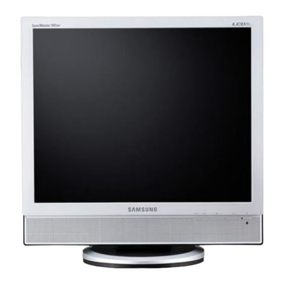
Page 60: O O Perating Instructions And Installation
10 Operating Instructions and Installation 10 Operating Instructions and Installation 10-1 Front 1. SOURCE 5. Power indicator Switches from PC Mode to Video mode. Power Indicator shows Power Saver mode by Changing the source is allowed only in external green blinking. devices that are connected to the monitor at the time. -
Page 61: Rear
10 Operating Instructions and Installation 10-2 Rear 1. POWER Power cord, plugs into monitor and wall receptacle. This product may be used with 100 ~ 240VAC (+/- 10%). 2. PC IN Computer Connection Terminal (15 Pin D-SUB) 10-2... - Page 62 10 Operating Instructions and Installation 3. PC AUDIO IN Audio Connection Terminal 4. EXT(RGB) External device terminal EXT(RGB) is mainly used in Europe. As for EXT(RGB) port of the monitor, it makes TV or Video signal input and output. 4. ANT IN TV Connection Terminal 10-3...
- Page 63 10 Operating Instructions and Installation 5. AV Connection Terminal 1. Headphone Connection Terminal (Output) 2. S-Video Connection Terminal (Input) 3. Video Connection Terminal (Input) 4. Right(R) / Left(L) audio Connection Terminal (Input) 6. Kensington Lock The Kensington lock is a device used to physically fix the system when using it in a public place.
-
Page 64: Remote Control
10 Operating Instructions and Installation 10-3 Remote Control 1. POWER 2. number buttons 3. -/-- (Volume) 5. MUTE 6. TTX/MIX 7. MENU 8. ENTER 10. SOURCE 11. INFO 12. EXIT 13. Up-Down Left-Right Buttons 14. AUTO / PRE-CH (MagicBright¢â) 20. S.MODE 16. - Page 65 10 Operating Instructions and Installation 1. POWER (MagicBright¢â) Use this button to turn the monitor on and off. PC Mode: MagicBright¢â is a new feature providing the opti- 2. Number button mum viewing environment depending on the con- Selects TV channels in the TV mode. tents of the image you are watching.
-
Page 66: Disassembly And Reassembly
11 Disassembly and Reassembly 11 Disassembly and Reassembly This section of the service manual describes the disassembly and reassembly procedures for the LS17DOA, LS19DOA TFT-LCD monitors. WARNING: This monitor contains electrostatically sensitive devices. Use caution when handling these components. 11-1 Disassembly Cautions: 1. - Page 67 11 Disassembly and Reassembly Description Picture Description 3. Remove 4 screws from the shield-cover and Disconnect cables. 4. Use the jig to remove the shield lamp. 5. Disconnect cables. 11-2...
- Page 68 11 Disassembly and Reassembly Description Picture Description 6. Remove the board. 7. Remove 4 screws. 11-3...
-
Page 69: Reassembly
11 Disassembly and Reassembly Description Picture Description 8. Lift up the LCD Panel 11-2 Reassembly -Reassembly procedures are in the reverse order of disassembly procedures. 11-4... -
Page 70: Pcb Diagram
12 PCB Layout 12 PCB Diagram 12 PCB Diagram 12-1... - Page 71 12 PCB Layout Memo 12-2...
-
Page 72: C C Ircuit Descriptions
13 Circuit Descriptions 13 Circuit Descriptions 13-1 Block description 13-1... - Page 73 13 Circuit Descriptions 13-1-1 VCT49XYI (IC700) 13-1-2 VSP Block : CVBS, S-Video, RF(IF), SCART (RGB) Convert 656 format to video input and transfer to MST51510 13-2...
- Page 74 13 Circuit Descriptions 13-1-3 MSP Block : PC, Sound L/R, SCART, Receive audio input and send out to AMP. 13-1-4 SE6181(IC301) - Scaler(MFM) - Support Digital Video Input - Internal LVDS IC - Support PIP - OSD controller engine 13-3...
- Page 75 13 Circuit Descriptions 13-1-5 Connect a Function Board to a Main Board 13-4...
-
Page 76: Reference Infomation
14 Reference Infomation 14 Reference Infomation 14-1 Technical Terms - TFT-LCD - Image Lock This means "Fineness adjustment " in LCD (Thin film Transistor Liquid Crystal Display) ADC(Analog to Digital Converter) Monitor, the features are "Fine" and "Coarse" This is a circuit that converts from analog signal to digital signals. - Page 77 14 Reference Infomation - Dot Pitch - DTV The image on a monitor is composed of red, green Broadcasting (Digital TV Broadcasting) and blue dots. The closer the dots, the higher the An enhanced broadcasting technology to process resolution. The distance between two dots of the digital video signals using a set-top box, which same color is called the 'Dot Pitch'.
- Page 78 - Channel Fine Tuning This feature allows the viewer to fine-tune the TV channel to obtain the best viewing conditions. The Samsung LCD TV has both automatic and manual channel fine-tuning features to enable the viewer to adjust their desired settings.
-
Page 79: Connecting Your Monitor
14 Reference Infomation 14-2 Connecting the Monitor - Connecting to a monitor Connect the power cord for your monitor to the POWER on the back of the monitor. Plug the power cord for the monitor into a nearby outlet. 2-1. Using the D-sub (Analog) connector on the video card. Connect the signal cable to the 15-pin, RGB port on the back of your monitor. -
Page 80: Connecting To Others Devices
14 Reference Infomation 14-3 Connecting to Other devices - Connecting AV Devices Input devices such as DVD, VCR or Camcorder are connected to the VIDEO or S-VIDEO terminal of the monitor using the Video or S-Video cable. * The S-Video cable is optional. Connect the Audio (R) and Audio (L) terminals of a DVD, VCR or Camcorders to the monitor's R and L audio input terminals using audio cables. - Page 81 14 Reference Infomation - Connecting TV Connect the CATV or antenna coaxial cable to the Antenna terminal on the rear of the monitor. You need to use a coaxial antenna cable. - When using an interior antenna terminal: Check the antenna terminal on the wall first and connect the antenna cable. - When using an outdoor antenna: If you are using an outdoor antenna, use a professional for installation if possible.
-
Page 82: Attaching A Base
14 Reference Infomation - Connecting Headphone Connect your headphones to the Headphone connection terminal. -Attaching a Base * This monitor accepts a 75 mm x 75 mm VESA-compliant mounting interface pad. A. Monitor B. Mounting interface pad (Sold separately) Turn off your monitor and unplug its power cord. Lay the LCD monitor face-down on a flat surface with a cushion beneath it to protect the screen. -
Page 83: Pin Assignment
14 Reference Infomation 14-4 Pin Assignments Sync 15-Pin Signal Cable Connector Type Separate Composite Pin No. Green Green Blue Blue GND (DDC Return) GND (DDC Return) GND-Red GND-Red GND-Green GND-Green GND-Blue GND-Blue DDC +5V DDC +5V CHK D_SUB CHK D_SUB DDC Data DDC Data Horizontal sync... -
Page 84: Timing Chart
14 Reference Infomation 14-5 Timing Chart This section of the service manual describes the timing that the computer industry recognizes as standard for computer- generated video signals. Mode VESA VGA2/ VGA3/ 640/75 Hz 800/60 Hz 800/75 Hz 1024/60Hz 1024/75Hz 1280/60Hz 1280/75Hz 1440/60Hz 1440/75Hz... -
Page 85: Preset Timing Modes
14 Reference Infomation 14-6 Preset Timing Modes -If the signal transferred from the computer is the same as the following Preset Timing Modes, the screen will be adjusted automatically. However, if the signal differs, the screen may go blank while the power LED is on. -
Page 86: Panel Description
14 Reference Infomation 14-7 Panel Description Maker VENDOR P/N PANEL_CODE PANEL_ABB STICKER_CODE Remarks LT140X1-002 BN07-00004A BN68-00239H LT150XS-L01 BN07-00009A LT150XS-L01-B BN07-00022A LTM150XS-L02 BN07-00005A LT181E2-132 BN07-00001A LT150XS-T01 BN07-00010A LTM181E3-132 BN07-00019A LT170E2-131 BN07-10001D LT181E2-131 BN07-10001E LTM170E4-L01 BN07-00018A LTM240W1-L01 BN07-00015A LTM213U3-L01 BN07-00016A LTM150XH-L01 BN07-00026A LTM150XH-L03 BN07-00027A LTM150XS-L01... - Page 87 14 Reference Infomation Maker VENDOR P/N PANEL_CODE PANEL_ABB STICKER_CODE Remarks LTM170E6-L04 BN07-00129A HIGHLAND 17" LOW PANEL (Panel only for TCO03) LTM190E1-L01 BN07-00088A LTM190E1-L01 ZPD panel M150X4-L06 BN07-00137A 15" Narrow & Slim panel LTA170V1 BN07-00139A 17" Panel for Muse 4:3 VGA TV LTM190E1-L02 BN07-00128A New Panel from AMLCDl, Specification : 6bit Driver IC...
- Page 88 14 Reference Infomation Maker VENDOR P/N PANEL_CODE PANEL_ABB STICKER_CODE Remarks LTA320W2-L11 BN07-00259A IP Board for AMLCD 32" 16:9 NEW Panel LTA460WS-L02 BN07-00252A AMLCD 46" 16:9 SPVA 72% NEW Panel LTA400WT-L01 BN07-00264A LTM240M2-L02 BN07-00267A All LCD Monitor 24" wide SPVA ZPD NEW code derivation LTM210M2-L02 BN07-00230A LTA320WT-L11...
- Page 89 14 Reference Infomation Maker VENDOR P/N PANEL_CODE PANEL_ABB STICKER_CODE Remarks TORISAN TM290WX-71N31 BN07-00063A RS24NS (TORISAN 29" NEW PANEL) TORISAN TM396WX-71N31 BN07-00064A RS24NS (TORISAN 40" NEW PANEL) TORISAN TM150XG-26L09 BN07-00073A Panel for 15" TV TORISAN TM150XG-26L10 BN07-00089A L10(change except D/IC) ZPD TORISAN TM150XG-26L10 BN07-00090A...
- Page 90 14 Reference Infomation Maker VENDOR P/N PANEL_CODE PANEL_ABB STICKER_CODE Remarks ACER M190EN04 BN07-00203A AU Monitor 19" ZPD New code Derivation ACER T260XW02 BN07-00208A AUO 26" ACER M170EG01 V8 BN07-00221A AU TN PSWG type New Panel (8msec) ZPD Derivation code ACER T260XW02 BN07-00233A AUO 26"...
- Page 91 14 Reference Infomation Memo 14-16...
Need help?
Do you have a question about the 741MP and is the answer not in the manual?
Questions and answers