Table of Contents
Advertisement
MCAC-UTSM-2008-05
Contents
Part 1 General Information .................................................................................................... 1
Part 2 Ceiling and Floor Type ................................................................................................ 6
Part 3 Outdoor Units............................................................................................................. 33
Part 4 Installation.................................................................................................................. 74
Part 5 Control........................................................................................................................ 99
Manufacture reserves the right to discontinue, or change at any time, specifications or designs without
notices and without incurring obligations.
Contents
i
Advertisement
Chapters
Table of Contents

Related Manuals for Midea MUB-12HRDN1-Q


Summary of Contents for Midea MUB-12HRDN1-Q
- Page 1 MCAC-UTSM-2008-05 Contents Part 1 General Information ....................1 Part 2 Ceiling and Floor Type ....................6 Part 3 Outdoor Units......................33 Part 4 Installation........................74 Part 5 Control........................99 Manufacture reserves the right to discontinue, or change at any time, specifications or designs without notices and without incurring obligations.
- Page 3 MCAC-UTSM-2008-05 General Information Part 1 General Information 1. Model Names of Indoor/Outdoor Units .......2 2. External Appearance.............3 3. Nomenclature ..............4 4. Features .................5 General Information...
-
Page 4: Model Names Of Indoor/Outdoor Units
MCAC-UTSM-2008-05 1. Model Names of Indoor/Outdoor Units 1.1 Indoor Units Model name Dimension W×H×D (mm) Net/Gross weight (kg) Power supply MUB-12HRDN1 990×206×660 27/33 220~240V-1ph-50Hz MUB-12HRDN1-Q 990×206×660 32/40 220~240V-1ph-50Hz MUB-18HRDN1-Q 990×206×660 34.5/42.5 220~240V-1ph-50Hz 1.2 Outdoor Units Net/Gross weight Model name Dimension W×H×D (mm) -
Page 5: External Appearance
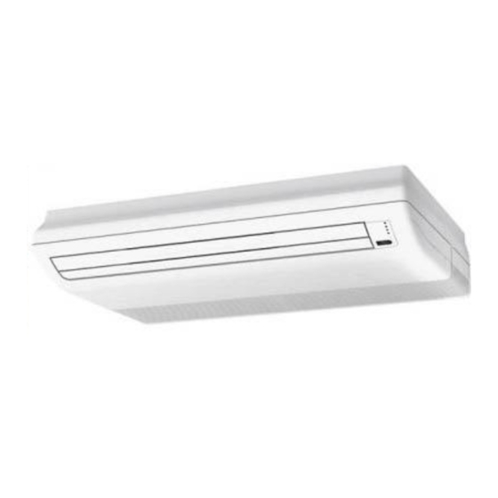
MCAC-UTSM-2008-05 External Appearance 2. External Appearance 2.1 Indoor units Ceiling and Floor Type: 12000Btu/h and 18000Btu/h 2.2 Outdoor unit 12000Btu/h 18000Btu/h General Information... -
Page 6: Nomenclature
Product Series A: First Time Design B: Second Time Design C: Third Time Design Product Category U: Ceiling & Floor Type Midea 3.2 Outdoor Units: M O U - 12 H D N1- Q Q: Quick Connector Refrigerant N1: R410A... -
Page 7: Features
MCAC-UTSM-2008-05 Features 4. Features 4.1 Universal outdoor unit design Indoor unit with the same capacity can match with the same outdoor unit. 4.2 High efficiency and energy saving. Thanks to the DC inverter technology and optimized piping system, the EER of whole series can easily reach A-class. -
Page 8: Table Of Contents
Ceiling and Floor Type MCAC-UTSM-2008-05 Part 2 Ceiling and Floor Type 1. Features .................7 2. Specifications ..............8 3. Dimensions ..............12 4. Service Space ..............13 5. Wiring Diagrams............16 6. Air Velocity and Temperature Distributions .....19 7. Capacity Tables ............21 8. Electric Characteristics ..........24 9. -
Page 9: Features
MCAC-UTSM-2008-05 Features 1. Features 1.1. New design, more modern and elegant appearance. 1.2. Convenient installation --The ceiling type can be easily installed into a corner of the ceiling even if the ceiling is very narrow --It is especially useful when installation of an air conditioner in the center of the ceiling is impossible due to a structure such as one lighting 1.3. -
Page 10: Specifications
Specifications MCAC-UTSM-2008-05 2. Specifications Table 1: Model name MUB-12HRDN1-Q MUB-18HRDN1-Q Indoor Units Power supply 220-240V-1Ph-50Hz 220-240V-1Ph-50Hz Model Model name MOU-12HRDN1-Q MOU-18HRDN1-Q Outdoor Units Power supply 220~240V-1Ph-50Hz 220~240V-1Ph-50Hz Capacity 4.0-3.5-1.4 5.65-5.27-1.7 Input 2.55-1.1-0.38 2.6-1.65-0.6 Cooling Rated current 12-5.1-2.0 12.3-7.8-2.5 Capacity 4.75-4.0-1.4 6.2-5.86-1.45... - Page 11 MCAC-UTSM-2008-05 Specifications Packing (W×H×D) 1105 x350 x805 1105 x350 x805 Net/Gross weight 32/40 34.5/42.5 Model YDK24-6G YDK53-6Y Brand Welling Welling Outdoor fan Input 59/43 129/86 motor Capacitor Speed r/min 800/550 770/560 Number of rows Tube pitch(a)x row pitch(b) 25.4×22 25.4×22 Fin spacing Fin type (code) Hydrophilic aluminium...
- Page 12 2.55-1.12-0.38 Heating Rated current 12-5.2-2.0 Max. input consumption 2550 Max. current Model DA108X1C-20FZ3 Type DC Inverter Rotary Brand MIDEA TOSHIBA Capacity Btu/h 10921 Compressor Input Rated current(RLA) Locked rotor Amp(LRA) Thermal protector Internal Refrigerant oil ESTER OIL VG74 480ml Model...
- Page 13 MCAC-UTSM-2008-05 Specifications Net/Gross weight 27/33 Model YDK24-6G Brand Welling Outdoor fan motor Input 59/43 Capacitor Speed r/min 800/550 Number of rows Tube pitch(a)x row pitch(b) 25.4×22 Fin spacing Fin type (code) Hydrophilic aluminium Outdoor coil Φ9.5 Tube outside dia. and type Innergroove tube Coil length x height x width 637×558×44...
-
Page 14: Dimensions
Dimensions MCAC-UTSM-2008-05 3. Dimensions 3.1 12HRDN1-Q MUB-18HRDN1-Q 3.2 MUB-12HRDN1-Q Capacity 12000Btu/h Ceiling and Floor Type... -
Page 15: Service Space
MCAC-UTSM-2008-05 Service Space 4. Service Space 4.1 MUB-12HRDN1-Q MUB-18HRDN1-Q Wall Mounting Installation: Ceiling and Floor Type... - Page 16 Service Space MCAC-UTSM-2008-05 Ceiling Installation: 4.2 MUB-12HRDN1 Wall Mounting Installation: Ceiling and Floor Type...
- Page 17 MCAC-UTSM-2008-05 Service Space Ceiling Installation: Capacity 12000Btu/h Ceiling and Floor Type...
-
Page 18: Wiring Diagrams
Wiring Diagrams MCAC-UTSM-2008-05 5. Wiring Diagrams 5.1 MUB-12HRDN1-Q Ceiling and Floor Type... - Page 19 MCAC-UTSM-2008-05 Wiring Diagrams 5.2 MUB-18HRDN1-Q Ceiling and Floor Type...
- Page 20 Wiring Diagrams MCAC-UTSM-2008-05 5.3 MUB-12HRDN1 Ceiling and Floor Type...
-
Page 21: Air Velocity And Temperature Distributions
MCAC-UTSM-2008-05 Air Velocity and Temperature Distributions 6. Air Velocity and Temperature Distributions Discharge angle 60°(Ceiling) Airflow velocity 1.5m/sec 0.5m/sec Temperature 27° C 22° C Ceiling and Floor Type... - Page 22 Air Velocity and Temperature Distributions MCAC-UTSM-2008-05 Discharge angle 60°(Floor) Airflow velocity 0.5m/sec 1.5m/sec Temperature 22° C 27° C Ceiling and Floor Type...
-
Page 23: Capacity Tables
MCAC-UTSM-2008-05 Capacity Tables 7. Capacity Tables 7.1 MUB-12HRDN1-Q: Cooling: Indoor temperature(°CWB) Outdoor 14.00 16.00 18.00 19.00 20.00 22.00 24.00 temperature(°C 21.00 2.42 0.43 2.86 0.54 3.30 0.64 3.50 0.70 3.70 0.75 3.78 0.75 3.86 0.76 23.00 2.42 0.46 2.86 0.57 3.30... - Page 24 Capacity Tables MCAC-UTSM-2008-05 7.2 MUB-18HRDN1-Q: Cooling: Indoor temperature(°CWB) Outdoor 14.00 16.00 18.00 19.00 20.00 22.00 24.00 temperature (°C DB) 10.00 3.65 0.55 4.31 0.69 4.97 0.82 5.27 0.89 5.57 0.96 5.69 0.96 5.82 0.97 12.00 3.65 0.56 4.31 0.70 4.97 0.84 5.27 0.91...
- Page 25 MCAC-UTSM-2008-05 Capacity Tables 7.3 MUB-12HRDN1: Cooling: Indoor temperature(°CWB) Outdoor 14.00 16.00 18.00 19.00 20.00 22.00 24.00 temperature (°C DB) 21.00 2.42 0.42 2.86 0.53 3.30 0.63 3.50 0.68 3.70 0.74 3.78 0.74 3.86 0.75 23.00 2.42 0.45 2.86 0.56 3.30 0.67 3.50 0.73...
-
Page 26: Electric Characteristics
Electric Characteristics MCAC-UTSM-2008-05 8. Electric Characteristics Indoor Unit Power Supply Model Voltage MUB-12HRDN1 220~240 0.025 0.15 MUB-12HRDN1-Q 220~240 0.025 0.15 MUB-18HRDN1-Q 220~240 0.55 0.52 Remark: MFA: Max. Fuse Amps. (A) KW: Fan Motor Rated Output (KW) FLA: Full Load Amps. (A) -
Page 27: Sound Levels
MCAC-UTSM-2008-05 Sound Levels 9. Sound Levels Ceiling Floor Noise level dB(A) Model MUB-12HRDN1 39.6 36.7 33.1 MUB-12HRDN1-Q 39.6 36.7 33.1 MUB-18HRDN1-Q 44.6 41.8 37.3 Ceiling and Floor Type... -
Page 28: Exploded View
Exploded View MCAC-UTSM-2008-05 10. Exploded View 10.1 MUB-12HRDN1-Q Ceiling and Floor Type... -
Page 29: Part
MCAC-UTSM-2008-05 Exploded View Part name Quantity Part name Quantity Filter Foam ass'y Grille clamp Foam ass'y Grille Evaporator Left support Grille clamp Foam ass'y Grille strengthening rib Support board Volute shell Evaporator right clapboard Grille lock Evaporator left clapboard Plastic fan Cover Motor clamp Display panel box... - Page 30 Exploded View MCAC-UTSM-2008-05 10.2 MUB-18HRDN1-Q Ceiling and Floor Type...
- Page 31 MCAC-UTSM-2008-05 Exploded View Part name Quantity Part name Quantity Filter Foam ass'y Grille clamp Foam ass'y Grille Evaporator Left support Grille clamp Foam ass'y Grille strengthening rib Support board Volute shell Evaporator right clapboard Grille lock Evaporator left clapboard Plastic fan Cover Motor clamp Display panel box...
- Page 32 Exploded View MCAC-UTSM-2008-05 10.3 MUB-12HRDN1 Ceiling and Floor Type...
- Page 33 MCAC-UTSM-2008-05 Exploded View Part name Quantity Part name Quantity Filter Foam ass'y Grille clamp Evaporator Left support Grille Foam ass'y Grille clamp Support board Grille strengthening rib Evaporator right clapboard Volute shell Evaporator left clapboard Grille lock Cover Plastic fan Display panel box Motor clamp Display board ass'y...
-
Page 34: Accessories
Accessories MCAC-UTSM-2008-05 11. Accessories Name of accessories Quantity Outline Usage Owner’s installation/remote controller manual Hook For wall mounting installation Hanging arm For ceiling installation Screw bolt with washer For ceiling installation Remote controller Frame Mounting screw(ST2.9×10-C-H) Alkaline dry batteries (AM4) Ceiling and Floor Type... - Page 35 MCAC-UTSM-2008-05 Outdoor Units Part 3 Outdoor Units 1. Dimensions..............34 2. Service Space..............35 3. Piping Diagrams..............36 4. Wiring Diagrams .............37 5. Electric Characteristics..........40 6. Sound Levels..............41 7. Exploded View..............42 8. Operation Limits .............47 9. Troubleshooting..............48 Outdoor Units...
-
Page 36: Dimensions
Dimensions MCAC-UTSM-2008-05 1. Dimensions Model MOU-12HDN1 MOU-12HDN1-Q MOU-18HDN1-Q Outdoor Units... -
Page 37: Service Space
MCAC-UTSM-2008-05 Service Space 2. Service Space Outdoor Units... -
Page 38: Piping Diagrams
Piping Diagrams MCAC-UTSM-2008-05 3. Piping Diagrams 3.1 MOU-12HDN1-Q MOU-12HDN1 Capillary ass'y Condenser Evaporator 4-way valve Compressor Indoor unit Outdoor unit 3.2 MOU-18HDN1-Q Electronic expansion valve ass'y Capillary Evaporator Condenser High pressure 4-way valve switch Low pressure switch Compressor Indoor unit Outdoor unit Outdoor Units... -
Page 39: Wiring Diagrams
MCAC-UTSM-2008-05 Wiring Diagrams 4. Wiring Diagrams 4.1 MOU-12HDN1-Q Outdoor Units... - Page 40 Wiring Diagrams MCAC-UTSM-2008-05 4.2 MOU-18HDN1-Q Outdoor Units...
- Page 41 MCAC-UTSM-2008-05 Wiring Diagrams 4.3 MOU-12HDN1 Outdoor Units...
-
Page 42: Electric Characteristics
Electric Characteristics MCAC-UTSM-2008-05 5. Electric Characteristics Outdoor Unit Power Supply Compressor Model Voltage Min. Max. TOCA MOU-12HDN1 220~240V 0.024 0.27 MOU-12HDN1-Q 220~240V 0.024 0.27 MOU-18HDN1-Q 220~240V 0.053 0.59 Remark: TOCA: Total Over-current Amps. (A) MFA: Max. Fuse Amps. (A) RLA: Rated Locked Amps. (A) OFM: Outdoor Fan Motor. -
Page 43: Sound Levels
MCAC-UTSM-2008-05 Sound Levels 6. Sound Levels Noise level dB(A) Model MOU-12HDN1 MOU-12HDN1-Q MOU-18HDN1-Q Outdoor Units... -
Page 44: Exploded View
Exploded View MCAC-UTSM-2008-05 7. Exploded View 7.1 MOU-12HDN1-Q No. Part name Quantity No. Part name Quantity Top cover Drainage pan E-part box ass'y Big handle 2.1 Main controller ass'y Discharge temp sensor ass'y 2.2 Compressor capacitor Condenser ass'y 2.3 Radiator 17.1 Condenser inlet pipe ass'y Grille 17.2 Condenser... - Page 45 MCAC-UTSM-2008-05 Exploded View 7.2 MOU-18HDN1-Q Outdoor Units...
- Page 46 Exploded View MCAC-UTSM-2008-05 No. Part name Quantity No. Part name Quantity Top cover ass'y Compressor Rear net frame Rear right clapboard ass'y E-part box ass'y Drainage cover Inverter radiator Big handle Transformer Discharge temp sensor ass'y Transformer Condenser ass'y Main controller ass'y 18.1 Output pipe ass'y Inverter control Module 18.2 Input pipe ass'y...
- Page 47 MCAC-UTSM-2008-05 Exploded View 7.3 MOU-12HDN1 Outdoor Units...
- Page 48 Exploded View MCAC-UTSM-2008-05 No. Part name Quantity No. Part name Quantity Top cover Drainage pan E-part box ass'y Big handle Main controller ass'y Discharge temp sensor ass'y Compressor capacitor Condenser ass'y Radiator 17.1 Condenser inlet pipe ass'y Main controller ass'y 17.2 Condenser 2.4.1 Rectifier 17.3 Condenser outlet pipe...
-
Page 49: Operation Limits
MCAC-UTSM-2008-05 Operation Limits 8. Operation Limits 8.1 For 12000Btu/h: Cooling mode Heating mode Item Model Outdoor Indoor Outdoor Indoor MOU-12HDN1 (-Q) 21℃~43℃ 17℃~30℃ -5℃~24℃ 17℃~30℃ Heating Cooling Indoor temperature( ℃ DB) Indoor temperature( ℃ WB) 8.2 For 1800Btu/h: Cooling mode Heating mode Item Model... -
Page 50: Troubleshooting
Troubleshooting MCAC-UTSM-2008-05 9. Troubleshooting 9.1 Indoor unit malfunction Running Timer Defrosting Alarm Malfunction lamp lamp lamp lamp Room temperature sensor checking channel is abnormal ☆ × × × Evaporator sensor checking channel is abnormal × × ☆ × In-outdoor unit communication checking channel is ×... - Page 51 MCAC-UTSM-2008-05 Troubleshooting 1. Running lamp flash at 5Hz: Room temperature sensor is abnormal Running lamp flash at 5Hz Judge: Room temperature sensor is abnormal Validate: Check whether the resistance of the Replace room temperature sensor temperature sensor is correct according to Annex 1 Replace indoor PCB 2.
- Page 52 Troubleshooting MCAC-UTSM-2008-05 3. Timer lamp flash at 5Hz: Communication malfunction between indoor/outdoor units Timer lamp flash at 5Hz Communication malfunction between indoor/outdoor units Judge 1: Check whether the indoor unit power is on Turn on the indoor unit power Judge 2: Check whether the signal wiring is shield cable or Adopt the shield cable/ shield cable earthing whether the shield cable is earthing Judge 3: Check whether the signal wiring between the...
- Page 53 MCAC-UTSM-2008-05 Troubleshooting 4. Alarm lamp flash at 5Hz: Water-level switch malfunction Alarm lamp flashes at 5Hz Exist Water-level switch Connecting Reconnect and ensure wire between switch and main that the connection is board gets loose reliable. Exist Replace switch There is something wrong with the water-level switch Error Chip fault, or chip foot sheds off, or chip is...
- Page 54 Troubleshooting MCAC-UTSM-2008-05 5. Running and Timer lamp flash at 5Hz: EEPROM malfunction Running and Timer lamp flash at 5Hz EEPROM malfunction Judge 1: Check whether the EEPROM is inserted well Insert the EEPROM well Replace outdoor main board Outdoor Units...
- Page 55 MCAC-UTSM-2008-05 Troubleshooting 6. Running lamp flash at 5Hz and Alarm lamp on: IPM protection Running lamp flash at 5Hz and Alarm lamp on IPM protection Regulate it to correct, then check whether the Check whether the voltage range of P-N on Check whether the input power supply system can work IPM module is normal?
- Page 56 Troubleshooting MCAC-UTSM-2008-05 7. Running lamp flash at 5Hz and Timer lamp on: Condenser temperature sensor is malfunction Running lamp flash at 5Hz and Timer lamp on Judge : Condenser temperature sensor is malfunction Check whether the wiring of the Condenser temperature sensor Connect the wiring well is break off Check whether the resistance of Condenser temperature sensor...
- Page 57 MCAC-UTSM-2008-05 Troubleshooting 8. Running lamp flash at 5Hz, Timer and Alarm lamp on: Outdoor unit voltage protection Running lamp flash at 5Hz, Timer and Alarm lamp on Outdoor unit voltage protection Check the voltage of outdoor unit power supply, whether the Check the power supply voltage between L1 and N is about 198-254V Replace the power board, then check whether the system can run normally...
- Page 58 Troubleshooting MCAC-UTSM-2008-05 9. Running lamp flash at 5Hz and Defrosting lamp on: Compressor discharge temperature protection Running lamp flash at 5Hz and Defrosting lamp on Compressor discharge temperature protection Check whether the compressor discharge temp. more than 115°C ? Check whether the wiring connection is right between compressor discharge temp.
- Page 59 MCAC-UTSM-2008-05 Troubleshooting 10. Running lamp 、Timer lamp and Alarm lamp flash at 5Hz: Outdoor unit current protection Running lamp 、Timer lamp and Alarm lamp flash at 5Hz Outdoor unit current protection Judge 1: Check whether the input current of the power supply wire is more than 16A.
- Page 60 Troubleshooting MCAC-UTSM-2008-05 9.2 Outdoor unit malfunctions: 12000Btu/h: Its malfunctions are displayed on the indoor units’ indicator. 18000Btu/h: Its malfunctions are displayed on the outdoor units’ digital tube. Display Malfunction or Protection EEPROM malfunction Communication malfunction between indoor/outdoor units Communication malfunction in outdoor PCB Outdoor temperature sensors malfunction Compressor voltage protection High pressure protection...
- Page 61 MCAC-UTSM-2008-05 Troubleshooting 2. E2 malfunction LED indicates E2 Communication malfunction between indoor/outdoor units Judge 1: Check whether the indoor unit power is on Turn on the indoor unit power Judge 2: Check whether the signal wiring is shield cable or Adopt the shield cable/ shield cable earthing whether the shield cable is earthing Judge 3: Check whether the signal wiring between the...
- Page 62 Troubleshooting MCAC-UTSM-2008-05 3. E3 malfunction LED indicates E3 Communication malfunction in outdoor PCB Check whether the indicator lights LED1 on the main board are flashing Replace the outdoor main board Insert the connecting wiring well Check whether the connecting wiring between the IPM module and over again the CN4 on the main board is break off Disconnect the connecting wiring between the IPM module and the...
- Page 63 MCAC-UTSM-2008-05 Troubleshooting 4. E4 malfunction LED indicates E4 Judge 1: Outdoor ambient temp. sensor (T4) is malfunction Check whether the wiring of the outdoor ambient temperature Connect the wiring well sensor (T4) is break off Check whether the resistance of outdoor ambient temperature Replace outdoor ambient sensor (T4) is wrong refer to the Annex 1 temperature sensor (T4)
- Page 64 Troubleshooting MCAC-UTSM-2008-05 5. E5 malfunction LED indicates E5 Outdoor unit voltage protection Check the voltage of outdoor unit power supply, whether the Check the power supply voltage between L1 and N is about 198-254V Replace the power board, then check whether the system can run normally Trouble is solved Replace outdoor main board Outdoor Units...
- Page 65 MCAC-UTSM-2008-05 Troubleshooting 6. P1 malfunction LED indicates P1 High pressure protection Judge 1: Whether the wiring between the high pressure switch Connect it well and main control board is connected well or correctly Judge 2: Whether the high pressure switch is broken Validate: Short connect the high pressure switch Replace high pressure switch socket, check whether the system can run normally...
- Page 66 Troubleshooting MCAC-UTSM-2008-05 7. P2 malfunction LED indicates P2 Low pressure protection Judge 1: The wiring between the low pressure switch and main control board is connected well or correctly Connect it well Judge 2: Whether the low pressure switch is broken Validate: Short connect the low pressure switch Replace low pressure switch socket, check whether the system can run normally...
- Page 67 MCAC-UTSM-2008-05 Troubleshooting 8. P3 malfunction LED indicates P3 Outdoor unit current protection Judge 1: Check whether the input current of the power supply wire is more than 18A Check whether the refrigerant system is ok Judge 2: Check whether the outdoor ambient temperature is too high Stop the unit Make the outdoor unit ventilate well Judge 3: Check whether the outdoor unit is bad ventilation...
- Page 68 Troubleshooting MCAC-UTSM-2008-05 9. P4 malfunction LED indicates P4 Compressor discharge temperature protection Check whether the compressor discharge temp. more than 115°C ? Check whether the wiring connection is right between compressor discharge temp. Correct the wiring connection sensor and PCB according to wiring diagrams Check whether the refrigerant is leakage Judge: The discharge temp.
- Page 69 MCAC-UTSM-2008-05 Troubleshooting 10. P5 malfunction LED indicates P5 Condenser high temperature protection Check whether the condenser temperature is more than 65°C Check whether the resistance of condenser Replace the temperature sensor temp. sensor is correct refer to the Annex 1 Replace outdoor main board Stop the unit Judge1: The outdoor temp.
- Page 70 Troubleshooting MCAC-UTSM-2008-05 11. P6 malfunction LED indicates P6 IPM protection Regulate it to correct, then check whether the Check whether the voltage range of P-N on Check whether the input power supply system can work IPM module is normal? is correct? 220-240V, 1N, 50Hz normally? Check whether the connecting line Check whether the power...
- Page 71 MCAC-UTSM-2008-05 Troubleshooting Annex 1 Resistance(KΩ) Temp.tol℃ Temp Resist.tol % (℃) Rmax R(t)Normal Rmin MAX(+) MIN(-) MAX(+) MIN(-) 116.539 106.732 96.920 9.19 9.19 1.59 1.59 110.231 100.552 91.451 9.63 9.05 1.57 1.57 103.743 94.769 86.328 9.47 8.91 1.56 1.55 97.673 89.353 81.525 9.31 8.76...
- Page 72 Troubleshooting MCAC-UTSM-2008-05 Resistance(KΩ) Temp.tol℃ Temp Resist.tol % (℃) Rmax R(t)Normal Rmin MAX(+) MIN(-) MAX(+) MIN(-) 14.442 13.902 13.372 3.89 3.81 0.81 0.79 13.748 13.251 12.762 3.75 3.69 0.79 0.76 13.093 12.635 12.183 3.62 3.57 0.77 0.74 12.471 12.050 11.634 3.50 3.46 0.75 0.72...
- Page 73 MCAC-UTSM-2008-05 Troubleshooting Resistance(KΩ) Temp.tol℃ Temp Resist.tol % (℃) Rmax R(t)Normal Rmin MAX(+) MIN(-) MAX(+) MIN(-) 2.682 2.534 2.390 5.86 5.69 1.56 1.52 2.585 2.440 2.299 5.93 5.76 1.59 1.54 2.491 2.350 2.213 6.01 5.83 1.62 1.57 2.401 2.264 2.130 6.08 5.90 1.64 1.60...
- Page 74 Troubleshooting MCAC-UTSM-2008-05 Resistance(KΩ) Temp.tol℃ Temp Resist.tol % (℃) Rmax R(t)Normal Rmin MAX(+) MIN(-) MAX(+) MIN(-) 0.697 0.646 0.597 7.93 7.63 2.62 2.59 0.677 0.627 0.579 7.94 7.64 2.64 2.61 0.657 0.609 0.562 7.94 7.65 2.67 2.64 0.638 0.591 0.546 7.95 7.65 2.70 2.67...
- Page 75 MCAC-UTSM-2008-05 Troubleshooting Annex 2 Unit: ℃---K Discharge temp. sensor table 542.7 68.66 13.59 3.702 511.9 65.62 13.11 3.595 62.73 12.65 3.492 455.9 59.98 12.21 3.392 430.5 57.37 11.79 3.296 406.7 54.89 11.38 3.203 384.3 52.53 10.99 3.113 363.3 50.28 10.61 3.025 343.6 48.14...
-
Page 76: Mcac-Utsm-2008-05 Part
Installation Place MCAC-UTSM-2008-05 Part 4 Installation 1. Installation Place............75 2. Installation of Indoor Unit ..........76 3. Installation of Outdoor Unit ........83 4. Refrigerant Piping Connection ........85 5. Connect the Drain Pipe ..........92 6. Wiring ................94 7. Test Operation.............98 Installation... -
Page 77: Installation Place
MCAC-UTSM-2008-05 Installation Place 1. Installation Place 1.1 The indoor Unit There is enough room for installation and maintenance. The ceiling is horizontal, and its structure can endure the weight of the indoor unit. The air outlet and the air inlet are not impeded, and the influence of external air is the least. The air flow can reach throughout the room. -
Page 78: Part 4 Installation
Installation of Indoor Unit MCAC-UTSM-2008-05 2. Installation of Indoor Unit 2.1 Service Space Installing Ø10 hanging screw bolts. (4 bolts) Please refer to the following figures for the distance measurement between the screw bolts. Please install with Ø10 hanging screw bolts. The handling to the ceiling varies from the constructions, consult the construction personnels for the specific procedures. - Page 79 MCAC-UTSM-2008-05 Installation of Indoor Unit New concrete bricks: Inlaying or embedding the screw bolts. For original concrete bricks: Install the hanging hook with expansible bolt into the concrete deep to 45~50mm to prevent loose. Steel for beam structure: Install and use directly the supporting angle steel. Installation...
- Page 80 Installation of Indoor Unit MCAC-UTSM-2008-05 2.2 Ceiling Installation: 1. Remove the side board and the grille. Installation...
- Page 81 MCAC-UTSM-2008-05 Installation of Indoor Unit 2. Cut a gap on the grill. 3. Local the hanging arm on the hanging screw bolt. Prepare the mounting bolts on the unit. Installation...
- Page 82 Installation of Indoor Unit MCAC-UTSM-2008-05 4. Hang the unit on the hanging arm by sliding backward. Securely tighten the mounting bolts on both sides. Note: The pipe must cross the gap which is cut on the grill in step two. Installation...
- Page 83 MCAC-UTSM-2008-05 Installation of Indoor Unit 2.3 Wall Mounting Installation: Installation...
- Page 84 Installation of Indoor Unit MCAC-UTSM-2008-05 1. Fix the hook with tapping screw onto the wall. 2. Hang the indoor unit on the hook. Installation...
-
Page 85: Installation Of Outdoor Unit
MCAC-UTSM-2008-05 Installation of Outdoor Unit 3. Installation of Outdoor Unit Caution: Keep this unit away from direct radiation of the sun or other heaters. If unavoidable, please cover it with a shelter. In places near coast or with a high attitude where the wind is strong, please install the outdoor unit against the wall to ensure normal performance. - Page 86 Installation of Outdoor Unit MCAC-UTSM-2008-05 3.2 Moving and Installing Since the gravity center of the unit is not at its physical center, so please be careful when lifting it with a sling. Never hold the inlet of the outdoor unit to prevent it from deforming. Do not touch the fan with hands or other objects.
-
Page 87: Refrigerant Piping Connection
MCAC-UTSM-2008-05 Refrigerant Piping Connection 4. Refrigerant Piping Connection Caution: For your safety, always wear safety eye wear and work gloves when connecting the pipes. 4.1 For MOU-12HDN1-Q and MOU-18HDN1-Q Remove the water tray before performing the connection. Installation... - Page 88 Refrigerant Piping Connection MCAC-UTSM-2008-05 To connect the couplings: Step 1: Ensure that the handle on the male coupling is in a reclined position away from the mating male coupling. Step 2: Retract the “Release Sleeve” on female coupling, insert the male coupling located on the indoor unit into the female coupling.
- Page 89 MCAC-UTSM-2008-05 Refrigerant Piping Connection 4.2 For MOU-12HDN1 Check whether the height drop between the indoor unit and outdoor unit, the length of refrigerant pipe, and the number of the bends meet the following requirements: Model MOU-12HDN1 When outdoor The max height unit is top drop(m) When outdoor unit is bottom...
- Page 90 Refrigerant Piping Connection MCAC-UTSM-2008-05 How to connect the pipes 1. Flaring: Cut a pipe with a pipe cutter. Insert a flare nut into a pipe and flare the pipe. Refer to the following table for the dimension of flare nut spaces. Flare dimension (A) Pipe gauge Tightening torque...
- Page 91 MCAC-UTSM-2008-05 Refrigerant Piping Connection Be sure to use both a spanner and torque wrench together when connecting or disconnecting pipes to /from the unit. Caution: Too large torque will harm the bell mouthing and too small will cause leakage. After the connecting work is finished, be sure to check that there is no gas leak. How to expel the air with a vacuum pump Stop valve operation introduction 1.
- Page 92 Refrigerant Piping Connection MCAC-UTSM-2008-05 Caution: Always use a charge hose for service port connection. After tightening the cap, check that no refrigerant leaks are present Using the vacuum pump Loosen and remove the maintenance nuts of stop valves A and B, and connect the charge hose of the manifold valve to the service port of stop valve A.
- Page 93 MCAC-UTSM-2008-05 Refrigerant Piping Connection 4.2.2 Additional Refrigerant Charge Caution: Refrigerant cannot be charged until field wiring has been completed. Refrigerant may only be charged after performing the leak test and the vacuum pumping. When charging a system, care shall be taken that its maximum permissible charge is never exceeded, in view of the danger of liquid hammer.
-
Page 94: Connect The Drain Pipe
Connect the Drain Pipe MCAC-UTSM-2008-05 5. Connect the Drain Pipe 5.1 Install the drainpipe of the indoor unit Caution: The drain pipe of indoor unit must be heat insulated, or it will condense dew, as well as the connections of the indoor unit. Hard PVC binder must be used for pipe connection, and make sure there is no leakage. - Page 95 MCAC-UTSM-2008-05 Connect the Drain Pipe 5.3 Drain Elbow Installation Fit the seal into the drain elbow, then insert the drain elbow into the base pan hole of outdoor unit, rotate 90o to securely assemble them. Connect the drain elbow with an extension drain hose (Locally purchased), in case of the condensate draining off the outdoor unit during the heating mode.
-
Page 96: Wiring
Secure the cable onto the control board with the cord clamp. Connect the ground wire (yellow &green) reliably with sheet-metal by screws. The electrical connection has finished now. For MUB-12HRDN1-Q: Outdoor unit: Indoor unit: Installation... - Page 97 MCAC-UTSM-2008-05 Wiring For MUB-18HRDN1-Q: Outdoor unit: Indoor unit: ① ② ③ ④ ⑤ ⑥ Number Area of the connecting wiring 4×0.5 3×2.5 4×1.5 4×0.5 2×2.5 3×1.5 6.2 For MOU-12HDN1 Caution: The appliance shall be installed in accordance with national wiring regulations. The air conditioner should use separate power supply with rated voltage.
- Page 98 Wiring MCAC-UTSM-2008-05 6.2.1 Connect the cable Dissemble the bolts from the cover.(If there isn't a cover on the outdoor unit, disassemble the bolts from the maintenance board, and pull it in the direction of the arrow to remove the protection board. Connect the connective cables to the terminals as identified with their respective matched numbers on the terminal block of indoor and outdoor units.
- Page 99 MCAC-UTSM-2008-05 Wiring 6.2.3 Wiring figure Note: All the pictures in this manual are for explanation purpose only. They may be slightly different from the air conditioner you purchased (depend on model).The actual shape shall prevail. Installation...
-
Page 100: Test Operation
Test Operation MCAC-UTSM-2008-05 7. Test Operation The test operation must be carried out after the entire installation has been completed. Please confirm the following points before the test operation: The indoor unit and outdoor unit are installed properly. Tubing and wiring are correctly completed. The refrigerant pipe system is leakage-checked. - Page 101 MCAC-UTSM-2008-05 Control Part 5 Control 1. Standard Controller ..........100 2. Optional Controller ...........105 Control...
- Page 102 Standard Controller MCAC-UTSM-2008-05 1. Standard Controller Wireless remote controller R05/BGE There‘s one model R05-BG/E for hereinafter type: MUB-12HRDN1、MUB-18HRDN1 The below is R05-BG/E wireless remote controller Visual photo Note: The outline figure on cover is for reference only, which may differ from what you purchased. Make sure to read chapter PRECAUTIONS before you operate the air conditioner.
-
Page 103: Part 5 Control
MCAC-UTSM-2008-05 Standard Controller Precautions Curtain, door or the similar objects will prevent the remote signal from being received by air conditioner. Do not get the interior of remote controller wet. It is forbidden to expose it to direct sunlight or locate it in the place with high temp. Malfunction may occur if infrared signal receiver on air conditioner is exposed to sunlight. - Page 104 Standard Controller MCAC-UTSM-2008-05 Buttons and their functions MODE: Once pressing, running mode will be selected in the following sequence: NOTE: No heating mode for cool only type unit. FAN SPEED: Fan speed will be selected in following sequence once pressing this button: Adjust: Decrease the set temp.
- Page 105 MCAC-UTSM-2008-05 Standard Controller Wind Vert Swing: Activate or turn off wind vertical swing function. (Only available when remote controller is used with corresponding unit.) CLOCK: Display the current time. (12:00 is displayed when resetting or electrifying for the first time.) Press CLOCK for 5s, icon indicating hour will flash with 0.5s.
- Page 106 Standard Controller MCAC-UTSM-2008-05 OPERATION INSTRUCTIONS Install and replace batteries Install 2 pieces of 7# alkaline batteries. Slide the cover to install batteries and make sure to place them in right pole. AUTO operation Switch on the power and running indicator light on indoor unit flashes. Press MODE to select AUTO.
- Page 107 MCAC-UTSM-2008-05 Optional Controller 2. Optional Controller 2.1The below is KJR-01B wired remote controller NAME AND FUNCTION OF INDICATORS ON THE WIRE CONTROLLER Control...
- Page 108 Optional Controller MCAC-UTSM-2008-05 WIRE CONTROLLER AND THEIR FUNCTIONS Installation Installation into the wall The diameter of Wire Controller wire must be suitable for its length. Wiring Tube must be suitable for the wires. Turn a screwdriver at the concave on bottom panel of the Wire Controller to remove the Cover. Control...
- Page 109 MCAC-UTSM-2008-05 Optional Controller NOTE ● Never turn screws too tightly, or else the cover would be dented, or the Liquid Crystal breaks. ● Do not cut wires when installing Wire Controller cover. Installation on the wall Cut a hole that can let a Three-core Rubber Insulating Screen Cable pass by from the middle of Wire Controller Top Cover before installation.
- Page 110 Optional Controller MCAC-UTSM-2008-05 2.2 The below is KJR-10B wired remote controller NAME AND FUNCTION OF LCD ON THE WIRE CONTROLLER Mode select button (MODE): Press MODE button to select “COOL”, “DRY” , "HEAT", or "FAN ONLY" mode.(HEAT is invalid for COOL ONLY wire controller.) AUTO→...
- Page 111 MCAC-UTSM-2008-05 Optional Controller Lock display Press LOCK to display the icon of LOCK. Press the button again then the icon of LOCK disappears. In the mode of LOCK, all the buttons are invalid except for LOCK button. CLOCK display Usually display the clock set currently. Press the button CLOCK for 4 seconds, the HOUR part will flash, press button ▲...
- Page 112 Optional Controller MCAC-UTSM-2008-05 CLOCK button: Normally display the clock set currently (display 12:00 for the first electrifying or resetting). When push the button for 4 seconds, the hour part on the clock display flashes every 0.5 seconds, then push button and to adjust hour;...
- Page 113 MCAC-UTSM-2008-05 Optional Controller NOTE Never turn screws too tightly, or else the cover would be dented or the Liquid Crystal breaks. Please leave enough long cable for maintenance of the Wire Controller Board. 2.3The below is KJR-12B wired remote controller Control...
- Page 114 Optional Controller MCAC-UTSM-2008-05 NAME AND FUCTION OF INDICATORS ON THE CONTROLLER Operation mode indication: When press” MODE” button, the following mode can be selected in circle. Auto Cool Dry Heat Fan only Auto. Auto→ Cool→ Dry →Heat→ Fan only →Auto For cooling only model, heat mode is skipped.
- Page 115 MCAC-UTSM-2008-05 Optional Controller NAME AND OPERATION OF THE BUTTON ON THE WIRE CONTROLLER Mode botton:When press this button, the operation mode change as the following sequence: Remark: For the cooling only model, the heating mode is skipped. Timer on button: Press this button, timer on function is active. Then every press, the time increase 0.5h, after 10h, 1h incensement after each press.
- Page 116 Optional Controller MCAC-UTSM-2008-05 12. Fan speed button: press this button consecutively; the fan speed will circle as follow: 13. Lock button (hidden): When you push the LOCK button, all current settings are locked in and the wire controller does not accept any operation except that of the LOCK button. Use the lock mode when you want to prevent setting from being changed accidentally or play fully.
- Page 117 MCAC-UTSM-2008-05 Optional Controller NOTE ● The connecting wire should be a little longer as to take away the switch board easily for maintenance. ● The connecting wire should be a little longer as to take away the controller easily for maintenance. 2.4The below is MDV-CCM01 indoor CCM Control...
- Page 118 Optional Controller MCAC-UTSM-2008-05 Name and Function of Indicators on CCM LCD Screen Common Display Data Common display data will be indicated in all display pages. a. Figure means CCM is in network control with PC or Gateway. b. Figure means CCM is in communication connection with Function Module. c.
- Page 119 MCAC-UTSM-2008-05 Optional Controller TEMP. Display TEMP. Display is applicable to the following: Set Temp. Ts(17-30℃), Indoor Return Air Temp. T1, Evaporator Pipe Temp. T2A, Evaporator Middle Pipe Temp. T2B, Condenser Pipe Temp. T3. And the allowable data display range is 0℃--99℃. If higher than 99℃, then display 99℃. If lower than 0℃, then display 0℃.
- Page 120 Optional Controller MCAC-UTSM-2008-05 Name and Function of Buttons on CCM Installation Adopt Electrical Switch Box The diameter of Central Control Monitor wire must be suitable for its length. Electrical wiring tube must be suitable for the wires. Turn a screwdriver at the concave on bottom panel of the Central Control Monitor to remove the cover. NOTE ●...
- Page 121 MCAC-UTSM-2008-05 Optional Controller Installation of CCM and NIM (1) Terminal P, Q, E at the back of CCM are connected to the terminal P, Q, E of PC. The CCM power connects 220V~ 50Hz power directly to the terminal L, N, At the back of wire controller.
- Page 122 Optional Controller MCAC-UTSM-2008-05 2.5The below is MD-CCM03 indoor CCM Control...
- Page 123 MCAC-UTSM-2008-05 Optional Controller Control...
- Page 124 Optional Controller MCAC-UTSM-2008-05 Liquid crystal matrix display description: The liquid crystal matrix is composed of 4*64 grids, and each grid is composed of two blocks of different sizes (as shown in the above figure). The matrix includes horizontal coordinates 00-15 on the upper side and vertical coordinates 00+, 16+, 32+ and 48+ on the left Side, which indicate the address of the indoor unit.
- Page 125 MCAC-UTSM-2008-05 Optional Controller Description of the query page The LCD displays the query page, and the air conditioner with the address of 08 is being queried. Mode of the air conditioner with the address 01 is: Cooling, strong air, swing on, indoor temperature 22℃, set temperature 20℃, cooling mode “lock”.
- Page 126 Optional Controller MCAC-UTSM-2008-05 Fault page display description Query the air conditioner with the address of 08 in the query page. The air conditioner with the address of 08 is faulty, and the fault code is 08. The big black dot below (08, 0+) blinks. In the matrix, only the big and small black dots from (00, 00+) to (16, 15+) illuminate.
- Page 127 MCAC-UTSM-2008-05 Optional Controller Name and Function of Indicators on the controller Operation mode indication: When press "MODE” and "ADD" or "REDUCE" button, the following mode can be selected in circle: Cool→ Heat→ Off. For cooling only model, heat mode should be skipped. Fan speed indication: There are four fan modes: low, middle, high, auto.
- Page 128 Optional Controller MCAC-UTSM-2008-05 Mode button: When press this button and ADD or REDUCE button to select Heat or Cool or off, press Confirm to save and back. Remark: For the cooling only model, the heating mode should be skipped. Fan speed button: press this button and ADD or REDUCE Button to select of High or Middle or Low or Auto, press Confirm to save and back.
- Page 129 MCAC-UTSM-2008-05 Optional Controller Instruction for installing: When a weekly schedule controller is needed, a small 2-cores wire and 3-cores wire should be added. Connect with the same color. Note ● The connecting wire should be a little longer as to take away the switch board easily for maintenance. ●...
Need help?
Do you have a question about the MUB-12HRDN1-Q and is the answer not in the manual?
Questions and answers