Advertisement
Quick Links
Advertisement

Related Manuals for Orbit Fitness OHG3067


Summary of Contents for Orbit Fitness OHG3067
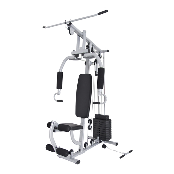
- Page 1 OHG3067 HOME GYM...
-
Page 2: Parts List Drawings
PARTS LIST DRAWINGS... - Page 3 PARTS LIST DRAWINGS...
- Page 4 ASSEMBLY INSTRUCTIONS STEP 1 1. Secure Base Frame (1) with Back Base Frame (2), using two M10X105mm Hex Bolt (62), four M10 Arc Washers (75) and two M10 Nylon Nuts (80). 2. Remove two M10X25mm Hex Bolts (65) and two M10 Washers (74) from two Weight Guide Tubes (13).
- Page 5 ASSEMBLY INSTRUCTIONS STEP2: 1. Slide nine Weight Plates (26) down two Weight Guide Tubes (13). 2. Slide Selector Shaft Bushing (27) down Selector Shaft (15) at first hole and fix with Selector Shaft Pin (28). 3. Insert Selector Shaft (15) into hole of Weight Plate (26). 4.
- Page 6 ASSEMBLY INSTRUCTIONS STEP 3: 1. Attach Main Upright Frame (5) to Base Frame (1) using two M10X105mm Hex Bolts (62), four M10 Washers (74) and two Nylon Nuts (80). 2. Remove two M10X25mm Hex Bolts (65) and two M10 Washers (74) from two Weight Guide Tubes (13).
- Page 7 ASSEMBLY INSTRUCTIONS STEP 4: 1. Attach Support Frame (11) to Main Upright Frame (5) using two M10X15mm Hex Bolts (66) and two M10 Washers (74). 2. Attach Seat Cushion Frame (6) to Main Upright Frame (5) and Support Frame (11) using two M10X60mm Hex Bolt (63), two M10X15mm Hex Bolts (66), six M10 Washers (74) and two M10 Nylon Nuts (80).
- Page 8 ASSEMBLY INSTRUCTIONS STEP 5: 1. Attach Butterfly Extension (4) to Top Cross Frame (3), using two Oil Bushing (small) (43), one M12×155mm Hex Bolt (60), two M12 Washers (73) and one M12 Nylon Nut (79). 2. Attach Tobacco-pipe (34) to Main Upright Frame (5) using one M8×40mm Hex Bolt (68), two M8 Washers (76) and one M8 Nylon Nut (81).
- Page 9 ASSEMBLY INSTRUCTIONS STEP 6: 1. Attach Leg Extension Frame (7) to Seat Cushion Frame (6), using one M12×75mm Hex Bolts (61), two M12 Washers (73) and one M12 Nylon Nuts (79). 2. Insert two Foam Tubes (14) into Seat Cushion Frame (6) and Leg Extension Frame (7). 3.
- Page 10 ASSEMBLY INSTRUCTIONS...
- Page 11 ASSEMBLY INSTRUCTIONS...
- Page 12 ASSEMBLY INSTRUCTIONS STEP 7: Start with the Upper Cable (39) a.) With Upper Cable (39) in groove of Pulley (36) through the Top Cross Frame (3). b.) Install Pulley NO.1 (36) to the Top Cross Frame (3) using one M10X45mm Hex Bolt (64), two M10 Washers (74) and one M10 Nylon Nut (80).
- Page 13 ASSEMBLY INSTRUCTIONS...
- Page 14 ASSEMBLY INSTRUCTIONS STEP 8: Assembly with the Butterfly Cable (40) a.) Attach the Butterfly Cable (40) to the Left Butterfly Arm (9) and the Right Butterfly Arm (8), using two Plastic Bushings (48). b.) Install Pulley NO.5&7 (36) to two Single Pulley Blocks (18), using two M10X45mm Hex Bolts (64), four M10 Washers (74) and two M10 Nylon Nuts (80).
- Page 15 ASSEMBLY INSTRUCTIONS...
- Page 16 ASSEMBLY INSTRUCTIONS STEP 9: Assembly the Lower Cable (41) a.) Install Pulley NO.8 (36) to the Low Pull Seat (19), using one M10X45mm Hex Bolt (64), two M10 Washers (74) and one M10 Nylon Nut (80). b.) Install Pulley NO.9 (36) to two Pulley Patches (16), using one M10X45mm Hex Bolt (64), two M10 Washers (74) and one M10 Nylon Nut (80).
- Page 17 ASSEMBLY INSTRUCTIONS STEP 10 1. Attach the Lat Bar (12) to the end of Upper Cable (39), using one Pothook (38). 2. Attach the Low Bar (20) or Ankle Strap (44) to the end of Lower Cable (41), using two Pothooks (38) and one Chain (37).
-
Page 18: Exploded Drawing
EXPLODED DRAWING... - Page 19 USER MANUAL...
-
Page 20: Part List
PART LIST... - Page 21 ASSEMBLY INSTRUCTIONS STEP 1 1. Attach L&R Base Tube (1) (3) to Main Base Tube (2), using two M10X100mm Hex Bolts (15), four M10 Arc Washers (22) and two M10 Nylon Nuts (16).
- Page 22 ASSEMBLY INSTRUCTIONS STEP 2 1. Attach Lower Main Tube (4) to Main Base Tube (2), using one M10X100mm Hex Bolts (15), two M10 Washers (24) and one M10 Nylon Nut (16). 2. Insert Upper Main Tube (5) to Lower Main Tube (4), using two M10X15mm Hex Bolts (19) and two M10 Arc Washers (22).
- Page 23 ASSEMBLY INSTRUCTIONS STEP 3 1. Attach VKR (6) to Upper Main Tube (5), using two M10X100mm Hex Bolts (15), four M10 Washers (24) and two M10 Nylon Nuts (16). 2. Remove two M10X25mm Hex Bolts (18) and two M10 Arc Washers (22) from two Handle Tubes (7).
- Page 24 ASSEMBLY INSTRUCTIONS STEP 4 1. Attach Backrest Cushion (13) to Upper Main Tube (5), using two M8X55mm Hex Bolts (21) and two M8 Washers (25). 2. Attach two Arm Cushions (14) to VKR (6), using four M8X65mm Hex Bolts (20) and two M8 Arc Washers (23).
- Page 25 ASSEMBLY INSTRUCTIONS STEP 5 ● Attach VKR Frame to OHG3067M as shown...
- Page 26 EXPLODED DRAWING...
Need help?
Do you have a question about the OHG3067 and is the answer not in the manual?
Questions and answers