Table of Contents
Advertisement
INPUT SELECTOR
2
TUNE
2
MENU
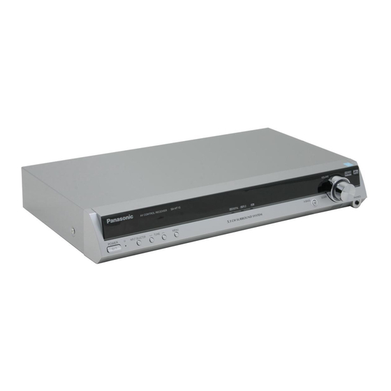
SC-HT17 for continental Europe and the United Kingdom
Dear customer
Thank you for purchasing this product.
Before connecting, operating or adjusting this product, please
read the instructions completely.
Please keep this manual for future reference.
SC-HT17 for continental Europe and the United Kingdom is
used in the illustrations unless otherwise mentioned.
Note:
"EB" on the packaging indicates the United Kingdom.
EP EB GN
VOLUME
%DIGITAL %PL
H. BASS
DOWN
UP
PHONES
Operating Instructions
Home Theater Audio System
Model No.
Table of contents
Caution for AC Mains Lead ................................... 2
Safety precautions................................................. 2
Supplied accessories ............................................ 3
The remote control ................................................ 3
Step 3
Operations
Basic operations .................................................. 15
Control guide........................................................ 16
The radio............................................................... 18
Other functions .................................................... 20
Making a recording .............................................. 22
The RESET function ............................................ 22
Remote control operation guide......................... 23
Reference
Troubleshooting guide ........................................ 26
Maintenance ........................................................ 26
Specifications ...................................................... 27
SC-HT17
SC-HT15
4
8
10
13
RQT7953-1B
Advertisement
Table of Contents

Related Manuals for Panasonic SC-HT17


Summary of Contents for Panasonic SC-HT17
-
Page 1: Table Of Contents
%DIGITAL %PL INPUT SELECTOR TUNE MENU SC-HT17 for continental Europe and the United Kingdom Dear customer Thank you for purchasing this product. Before connecting, operating or adjusting this product, please read the instructions completely. Please keep this manual for future reference. SC-HT17 for continental Europe and the United Kingdom is used in the illustrations unless otherwise mentioned. -
Page 2: Before Use
• Most major credit and debit cards accepted. • All enquiries transactions and distribution facilities are provided directly by Panasonic UK Ltd. • It couldn’t be simpler! • Also available through our Internet is direct shopping for a wide range of finished products, take a browse on our website for further details. -
Page 3: Supplied Accessories
Supplied accessories Please check and identify the supplied accessories. AC mains lead For the United For continental Kingdom Europe (RJA0053-3X) (RJA0019-2X) System cable FM indoor antenna AM loop antenna Remote control transmitter Batteries Speaker cable(s) (REE1203A) (4 m x 1) (REE1203A) (4 m x 1) (REE1203C) (10 m x 2) Rubber pads... -
Page 4: Step 1 Speaker Setup
Speaker setup Step Speaker stands with long cables Supplied accessories Front and surround speaker assembly • To prevent damage or scratches, lay a soft cloth and perform assembly on it. • For assembly, use a Phillips-head screwdriver. Attach the pipe to the base. Thread the speaker cable through the base. - Page 5 Large screws Small screws (x 8) SC-HT17 SC-HT15 (x 4) Connect the speaker cables. Copper Silver Fasten the speaker cable to the base. Attach the stickers to the speaker cables. Front speaker (L) xxxxxx xxxxxx xxxxxx xxxxxx xxxxxx xxxxxx xxxxxx xxxxxx xxxxxx xxxxxx...
- Page 6 Speaker setup Placement and connections of speakers Place the speakers. e.g., SC-HT17 Center speaker Front speaker (L) Front speaker (R) Subwoofer Surround speaker Place the front, center, and surround speakers at approximately the same distance from the seating position. The angles in the diagram are approximate. Front speakers (left, right) Place on the left and right of the TV at seated ear height so that there is good coherency between the picture and sound.
-
Page 7: Attaching To A Wall
Connect the speaker cables to the subwoofer. SC-HT17 SC-HT15 Copper Silver FRONT (L) 6 Ω 4 Ω FRONT SURROUND FRONT (R) Copper Silver Other speaker setup options Attaching to a wall 180 mm 30 - 35 mm Wall or pillar 7.5 - 9.4 mm 7 - 9 mm Screw... -
Page 8: Home Theater Step 2 Connections
Home theater connections Step Stereo phono cable Other (not included) accessories Left Right Coaxial cable (not included) Turn off all components before making any connections. To connect equipment, refer to the appropriate operating instructions. DVD player TV (Monitor) VIDEO LOOP FRONT SURROUND SUBWOOFER GAME/AUX DVR / VCR... - Page 9 Supplied System cable accessories Changing the digital input settings You can change the input settings for the digital terminals if necessary. Note the equipment you have connected to the terminals, then change the settings ( è Note • The included AC mains lead is for use with this unit only. Do not use it with other equipment.
-
Page 10: Other Connections
Other connections Step Stereo phono cable Other (not included) accessories Left Right Optical fibre cable (not included) DVD recorder or VCR COMPONENT VIDEO terminals This connection provides high quality pictures by separating the colour and P ) and the luminance (Y) signals. TV MONITOR COMPONENT VIDEO LOOP... - Page 11 Changing the digital input settings You can change the input settings for the digital terminals if necessary. Note the equipment you have connected to the terminals, then change the settings ( page 13). è TV (Input source) COMPONENT VIDEO terminals This connection provides high quality pictures by separating the colour and P ) and the luminance (Y) signals.
- Page 12 Other connections Stereo phono cable (not included) Other Left accessories Right Antennas FM indoor antenna (included) Adhesive tape Fix the end of the antenna where reception is best. TO SB-WA17 Keep the antenna cord away from DVD players and other cords. Game machine or other AV equipment SC-HT17 LOOP...
-
Page 13: Step 4 Settings
Settings Step Change the settings to suit your equipment to the environment in which you are using it. Before making any changes, read the descriptions of the settings, note the factory settings and ranges, and refer to the equipment’s instructions. DISTANCE See below è... - Page 14 Settings Adjusting speaker output level -LEVEL/ - TEST Press and hold Output the Adjust the main signal. volume. C (center), RS (right surround) and LS (left surround) can be adjusted between –10 dB and +10 dB, with 0 dB being the level of the front speakers.
-
Page 15: Basic Operations
Basic operations INPUT SELECTOR TUNE MENU INPUT SELECTOR Switch on. Select input. TUNER GAME/AUX (SC-HT17) When playing video sources connected to DVD The picture remains on the screen even if you select TUNER. Adding surround effects to stereo sources Using Dolby Pro LogicII Dolby Pro LogicII processor works not only on sources recorded with Dolby Surround, but also on any stereo source. -
Page 16: Control Guide
Control guide Main unit Standby indicator [^] When the unit is connected to the AC mains supply, this indicator lights up in standby mode and goes out when the unit is turned on. Standby/on switch [8] Press to switch the unit from on to standby mode or vice versa. - Page 17 Remote control and Subwoofer This page describes the buttons used to control this unit. See the guide starting page 23 for the buttons that control other units. [^, RECEIVER] Standby/on button. [1, 2, 3, 4, 5, 6, 7, 8, 9, 0] enter radio frequencies...
-
Page 18: The Radio
The radio RECEIVER AV SYSTEM DRIVE SELECT RECORDER DIRECT TUNING DISC DIRECT TUNING -/-- SKIP > DISC STOP DIRECT NAVIGATOR TOP MENU SUB MENU/ PLAY LIST TV VOL DVD REC REC MODE INPUT MODE SUBWOOFER TONE/ BALANCE EFFECT Direct tuning Input the frequency of the station. - Page 19 The radio INPUT SELECTOR TUNE RDS broadcasts (For continental Europe and the United Kingdom) This unit can display the text data transmitted by the radio data system (RDS) available in some areas. “RDS” lights while RDS signals are being received. RDS displays may not be available if reception is poor.
-
Page 20: Other Functions
Other functions TUNE MENU INPUT SELECTOR Input mode This unit automatically detects whether input is digital or analogue, but you can fix the input mode. Remote control Press [INPUT MODE] to select "AUTO", "ANALOG" or "DIGITAL". Tone You can adjust the level of the bass and treble. Remote control 1. - Page 21 Other functions TUNE INPUT SELECTOR INPUT SELECTOR TUNE MENU A/D attenuator Turn the A/D attenuator on if “OVERFLOW” lights frequently when using 2-channel analogue input. Main unit 1. Press [TUNE 2 and 1] at the same time to enter the setup mode.
-
Page 22: Making A Recording
Other functions TOP MENU ENTER SUB MENU/ PLAY LIST TV VOL DVD REC REC MODE TV/AV - H.BASS/ INPUT MODE SUBWOOFER - C.FOCUS EFFECT TONE/ EFFECT BALANCE MUSIC Center Width Control "C-WDTH" You can adjust the effect of MUSIC and PANORAMA with the center width control. -
Page 23: Remote Control Operation Guide
Remote control operation guide This remote control can operate Panasonic and Technics audiovisual components that have remote control sensors. You may need to change the remote control code. (è page 25) Note that this remote control cannot operate some equipment and that it may not be able to perform some operations. - Page 24 Remote control operation guide TV/VCR Watching TV Switch on RECEIVER AV SYSTEM PLAYER ANALOG 6CH - TUNER/ DRIVE SELECT RECORDER - BAND VOLUME -/-- DIRECT TUNING > DISC SKIP SLOW/SEARCH STOP PAUSE PLAY Switch off DIRECT NAVIGATOR FUNCTIONS TOP MENU Operating the TV ENTER SUB MENU/...
- Page 25 Using this remote control to operate equipment manufactured by Panasonic, Technics, and other companies It can also operate some other brands of televisions, video cassette players, and DVD players. Check the table for the brand and enter the code as follows.
-
Page 26: Troubleshooting Guide
Troubleshooting guide Before requesting service, make the below checks. If you can’t fix the unit as described or if something not listed here occurs, contact your dealer. No power. No sound. “F76” appears on the display, and the unit turns off. -
Page 27: Specifications
Specifications (DIN 45 500) n AMPLIFIER SECTION RMS output power of each channel driven (at 240 V for areas other than continental Europe) 10 % total harmonic distortion [SC-HT17] 170 W per channel (6 Ω) 1 kHz front CH [SC-HT15] 60 W per channel (4 Ω) [SC-HT17] 70 W per channel (4 Ω) 1 kHz surround CH [SC-HT15] 60 W per channel (4 Ω) - Page 28 Do not place anything on top of this unit or block the heat radiation vents in any way. In particular, do not place tape decks or CD/DVD players on this unit as heat radiated from it can damage your software. Matsushita Electric Industrial Co., Ltd. Web Site: http://www.panasonic.co.jp/global/ RQT7953-1B H0205MT1035...