Table of Contents
Advertisement
DENSITÉ series
LGK-3901
3G/HD/SD Logo Inserter & Downstream Keyer
DSK-3901
3G/HD/SD Downstream Keyer
Guide to Installation and Operation
M887-9900-200
25 Jan 2010
Miranda
Technologies Inc.
3499 Douglas-B.-Floreani
St-Laurent, Québec, Canada H4S 1Y6
Tel. 514-333-1772
Fax. 514-333-9828
www.miranda.com
© 2010 Miranda Technologies Inc.
Advertisement
Table of Contents

Subscribe to Our Youtube Channel
Related Manuals for Miranda DENSITE LGK-3901


Summary of Contents for Miranda DENSITE LGK-3901
- Page 1 LGK-3901 3G/HD/SD Logo Inserter & Downstream Keyer DSK-3901 3G/HD/SD Downstream Keyer Guide to Installation and Operation M887-9900-200 25 Jan 2010 Miranda Technologies Inc. 3499 Douglas-B.-Floreani St-Laurent, Québec, Canada H4S 1Y6 Tel. 514-333-1772 Fax. 514-333-9828 www.miranda.com © 2010 Miranda Technologies Inc.
-
Page 2: Compliance Information
EN 55024 Class A, Conducted Emissions EN 61000-4-2, -4-5, -4-11, Electromagnetic Immunity EN 61000-3-2 & -3-3, Electromagnetic Disturbance in Supply Systems How to contact us: For technical assistance, please contact the Miranda Technical support centre nearest you: Americas Asia Europe, Middle East, Africa, UK... -
Page 3: Table Of Contents
GUIDE TO INSTALLATION AND OPERATION Visit our web site at www.miranda.com Table of Contents LGK-3901 3G/HD/SD Logo Inserter & Downstream Keyer ............. 1 Introduction ............................1 Features .............................. 2 Functional Block Diagram ........................3 DSK-3901 3G/HD/SD Downstream Keyer................. 4 Introduction ............................4 Features .............................. - Page 4 GUIDE TO INSTALLATION AND OPERATION 4.9.1 Preview Input / Mix B Input....................32 4.9.2 Preview Output ........................32 4.9.3 Active Preview ........................33 4.10 General Purpose Interface (GPI).......................34 4.10.1 GPI Inputs and Macros......................34 4.10.2 GPI Outputs and Events.......................35 4.11 Graphics Co-Processors ........................36 4.11.1 Command Forwarding to a Co-Processor................36 4.11.2 Automatic Keyer Management .....................38 4.12 Closed Captions ..........................40 4.13 Timecode ............................40...
- Page 5 GUIDE TO INSTALLATION AND OPERATION 6.4.4 Video Config......................... 60 6.4.5 Reference..........................60 6.4.6 Timecode ..........................61 6.4.7 Monitoring ..........................62 6.4.8 Show Signal Path......................... 63 6.4.9 Web Page ..........................63 6.4.10 Test ............................64 6.4.11 Hardware Config ........................64 6.4.12 Options..........................65 6.4.13 Alarm Config ........................
- Page 6 GUIDE TO INSTALLATION AND OPERATION 9.2.1 DSK-3901-SD........................93 9.2.2 DSK-3901-HD-UPG......................93 9.2.3 DSK-3901-UPG ........................93 9.2.4 DSK-3901-OPT-AUD......................93 9.2.5 DSK-3901-OPT-ABMIX ......................93 10 Specifications .......................... 94 ANNEX 1 – Front Panel Menu ....................... 96 ANNEX 2 – GPI Output Event List ....................121 LGK-3901/DSK-3901...
-
Page 7: Lgk-3901 3G/Hd/Sd Logo Inserter & Downstream Keyer
GUIDE TO INSTALLATION AND OPERATION 1 LGK-3901 3G/HD/SD Logo Inserter & Downstream Keyer 1.1 Introduction The Densité LGK-3901 is a low cost, single card channel branding processor, capable of inserting up to five layers of graphics into 3G/HD/SD. Three of the keying layers can be fed by internally stored still/animated graphics, and two layers are fed by external graphics devices. -
Page 8: Features
GUIDE TO INSTALLATION AND OPERATION 1.2 Features MODULAR, 3G/HD/SD BRANDING PROCESSOR • Single, modular card channel branding processor • Module is housed in Densité 3 frame, with up to 10 cards (channels) per frame • Supports 3G/HD/SD (1080p59.94, 1080p50, 1080i59.94, 1080i50, 720p59.94, 720p50, 525i59.95, 625i50) •... -
Page 9: Functional Block Diagram
GUIDE TO INSTALLATION AND OPERATION 1.3 Functional Block Diagram The following block diagram shows the full functionality of the LGK-3901. Figure 1.1 Functional block diagram LGK-3901 There are line FIFOs for each video input feeding two video channels (PGM and PVW). Embedded audio is passed through unchanged, or manipulated by the audio engine (requires the LGK-3901-OPT-AUD option). -
Page 10: Dsk-3901 3G/Hd/Sd Downstream Keyer
GUIDE TO INSTALLATION AND OPERATION 2 DSK-3901 3G/HD/SD Downstream Keyer 2.1 Introduction The Densité DSK-3901 is a low cost, single card downstream keyer, with two independent pairs of fill and key inputs. This 3G/HD/SD keyer is ideal for inserting two external character generator feeds over program video. Up to 10 channels of keying can be housed in a single 3RU Densité... -
Page 11: Features
GUIDE TO INSTALLATION AND OPERATION 2.2 Features MODULAR, 3G/HD/SD DOWNSTREAM KEYER • Single, modular card downstream keyer with dual, independent fill and key inputs • Two independent keying layers fed by external graphics devices (dual fill & key inputs) • Independent preview output •... -
Page 12: Functional Block Diagram
GUIDE TO INSTALLATION AND OPERATION 2.3 Functional Block Diagram The following block diagram shows the full functionality of the DSK-3901. Figure 2.1 Functional block diagram DSK-3901 There are line FIFOs for each video input feeding two video channels (PGM and PVW). Embedded audio is either passed through unchanged, or manipulated by the audio engine (requires the DSK-3901-OPT-AUD option). -
Page 13: Applications
GUIDE TO INSTALLATION AND OPERATION 3 Applications 3.1 Downstream Branding In many cases, branding is done downstream of a Master Control switcher. In this scenario an LGK-3901 may be used for basic logo insertion (station logo, ratings, etc.). Moreover, advanced graphics can be achieved using an external graphics co-processor. -
Page 14: Rich Graphics Keying - (Dsk-3901)
GUIDE TO INSTALLATION AND OPERATION 3.2 Rich Graphics Keying – (DSK-3901) This is a variant of the Downstream Branding application but without any basic logo insertion capability. A DSK-3901 card is supplied with rich graphical content from external graphics co-processor(s). Voice-overs may be supplied via embedded audio on one of the Fill inputs, or via external AES inputs. -
Page 15: Downstream Parallel Branding
GUIDE TO INSTALLATION AND OPERATION 3.3 Downstream Parallel Branding This is a variant of the LGK-3901 Downstream Branding application, where one Master Control switcher feeds several branding devices in parallel. This scenario is usually seen when the same signal has to be branded differently, for different channels or different regions. -
Page 16: Low-Cost Channel Branding For Specialty Channels
GUIDE TO INSTALLATION AND OPERATION 3.4 Low-Cost Channel Branding for Specialty Channels In the case of specialty channels, a Master Control switcher may not be needed as most content is played out directly from a server. There is no need to perform transitions from a server feed to a live feed and vice-versa. For this scenario, branding can be done on an LGK-3901 directly downstream of the server playout port, and for the low-end part of the specialty channels, a simple logo inserter may be ideal. -
Page 17: Master Control Switching
GUIDE TO INSTALLATION AND OPERATION 3.5 Master Control Switching The LGK-3901 can be used as a traditional Master Control switcher, as it includes an optional AB mixer. In the case where live events need to be handled, the LGK-3901 is a compact and economic solution for stations which need a transition engine without all the features that typically burden the cost &... -
Page 18: Master Control Backup
GUIDE TO INSTALLATION AND OPERATION 3.6 Master Control Backup In a traditional playout chain, a small utility router is typically used as a low-cost backup for the main master control path. Indeed, a small router is cheaper than a full Master Control switcher, and moreover, this configuration allows the backup path to bypass not only the Master Control switcher but also the main station router. -
Page 19: Features
GUIDE TO INSTALLATION AND OPERATION 4 Features 4.1 Front Card-Edge Interface The front card-edges of the two cards of the LGK-3901/DSK-3901 incorporate six elements. Figure 4.1 Front card-edge layout 4.1.1 CPU Card Front Edge The CPU card is the left-hand of the two cards. Its three elements are as follows (top-to-bottom): •... -
Page 20: Fpga Card Front Edge
GUIDE TO INSTALLATION AND OPERATION 4.1.2 FPGA Card Front Edge The FPGA card is the right-hand of the two cards. Its three elements are as follows (top-to-bottom): • Watchdog When green, the software is active and continually writing to the hardware watchdog. PGM and PVW outputs are driven by the card, and the bypass relay on the rear panel is disabled.. -
Page 21: Video Standards
GUIDE TO INSTALLATION AND OPERATION 4.3 Video Standards 4.3.1 Output The following SDI video standards can be transmitted: • 525i / 59.94 Hz SMPTE 259M-1997 270Mb/s • 625i / 50 Hz SMPTE 259M-1997 270Mb/s • 1920 x 1080i / 59.94 Hz SMPTE 274M-1998 1.485Gb/s •... -
Page 22: Reference
GUIDE TO INSTALLATION AND OPERATION 4.4 Reference 4.4.1 Reference Types The LGK-3901/DSK-3901 will lock to one of the following inputs, in order or priority: • Universal Reference Signal (URS) from a Densité REF-1801, if present and enabled • REF IN Analogue Reference Input, if present and compatible •... -
Page 23: Hd-Sdi Example (1080I)
GUIDE TO INSTALLATION AND OPERATION • Loss of timecode • Loss of closed captions • Errors in embedded audio • Errors in Dolby E streams An SDI data analyzer is needed to monitor the timing of the SDI input sources and the outputs with respect to the facility reference. - Page 24 GUIDE TO INSTALLATION AND OPERATION To buffer half a line of 1080i / 59.94, increase the above reference timing to: 0 line +4.3µs (+15µs) = 0 line +19.3µs. Note: If the path delay of the SDI input sources is such that they are all offset from reference by several lines then adjust the reference by the same number of lines to align the output to the unusual input timing.
-
Page 25: Audio Processing
GUIDE TO INSTALLATION AND OPERATION 4.5 Audio Processing Audio processing requires the LGK-3901-OPT-AUD or DSK-3901-OPT-AUD audio option to be enabled. The audio engine provides the following possible features: • Input selection from embedded SDI or external AES • AB mixing of multi-channel audio sources for cuts and variable rate fades •... -
Page 26: Example Route Manager Templates
GUIDE TO INSTALLATION AND OPERATION Some audio blocks are controlled by automation, and others may be set up to automatically follow other system states; for example audio AB mixing may follow video AB mixing and Easyplay clips may drive voice-overs and/or follow the up/down state of keying layers on Program or Preview. -
Page 27: Easyplay
GUIDE TO INSTALLATION AND OPERATION The Duck value sets the amount by which the background audio level is attenuated when the voice-over is fully on. The Preset value sets the level of the voice-over audio when the voice-over is fully on. Both values are measured in decibels. -
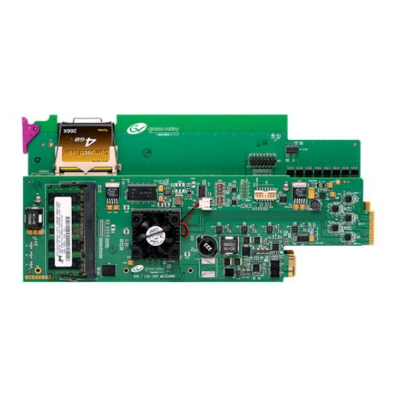
Page 28: Store Memory
The store memory is physically located as shown in the accompanying diagram. DSK-3901 may be upgraded to LGK-3901 by the addition of store memory and appropriate options, both purchasable from Miranda Technologies Inc (see section 9.2.3). Figure 4.3 Store Memory location Media files are always pre-loaded into the store memory prior to being keyed over background video. -
Page 29: Keying Graphics
GUIDE TO INSTALLATION AND OPERATION 4.8 Keying Graphics Keying is the process of inserting one video signal (the Fill signal) into another video signal (the Background signal) according to a third signal (the Key signal). Graphics fill/key signals may be sourced from the following methods: •... - Page 30 Xplorer • Animation Builder (available from the MCS CD) • Miranda Adobe After Effects Plug-in (available from the MCS CD) 4.8.2.3 Easytext Easytext requires the LGK-3901-OPT-TXT option. CG text effects including static text and simple crawls are defined within OXA Easytext files, or templates. These templates may comprise of many text and/or image elements, all of which may be updated dynamically via automation.
-
Page 31: Emergency Alert System (Eas)
Air feature. This may be triggered from automation (see Oxtel Automation Protocol v15), GPI, control panel (such as the Miranda RCP-BR) or the front panel. When Emergency To Air is selected, the most downstream keyer that is associated with a store (on the program output channel) is faded down over 25 fields. - Page 32 • Since most receivers have analogue audio outputs, the audio will first need to be converted to AES using an external converter such as the Miranda ADC-1711 or ASD-771p. • The AES audio is then fed to the LGK-3901 via an external AES input pair and the audio is mixed onto the background via a voiceover.
- Page 33 ‘Voiceover On’ and ‘Voiceover Off’ command and appropriate delays to ensure that the data for the crawl is received. Such GPI macros are outside the scope of this manual, but can be discussed with Miranda Support. As the LGK-3901 retains the last EAS text message received, the EASNone.oxa crawl will only be seen when the EAS mode is activated with no alert level.
-
Page 34: Temperature Probe
3503-0024-0 Sensorsoft C2000 Cable, DB9-to-RJ45, 20 feet 1897-1700-100 Miranda Adapter, RJ45-to-DE-9 for RS232 DTE 0702-1400-100 Ethernet Cable, RJ45-to-RJ45 CAT5 UTP, Flex 10 feet Note: For pin-outs to be correct at the LGK-3901, parts must be connected in the order listed in the table above. -
Page 35: Keying Parameters
GUIDE TO INSTALLATION AND OPERATION 4.8.5 Keying Parameters The following Keying Parameters may be adjusted for both internal graphics (LGK-3901 only) and external graphics (LGK-3901/DSK-3901). 4.8.5.1 Source The Key source may be chosen from the following: • Separate Key The key data is derived from the luminance content (Y value) of the separate Key. •... - Page 36 GUIDE TO INSTALLATION AND OPERATION Figure 4.4 Linear Keying Full keying is where the Fill signal needs to be multiplied by the Key signal prior to being added to the modified Background signal. In this case, the Fill has not already been cut by its key external to the LGK-3901/DSK-3901. The card cuts a hole in the Fill with the Key and then cuts a hole in the Background with a computed (1 - Key) signal.
- Page 37 GUIDE TO INSTALLATION AND OPERATION 4.8.5.5 Masking The LGK-3901/DSK-3901 allows a rectangular masking area to be defined for each of the five keyers. This mask applies to any signals fed into the keyer; external fill/key signals, or the output from internal stores (LGK-3901 only). For internal images (LGK-3901 only), the area range of the mask is determined by the width and height of the image in pixels, and is limited by the selected video standard.
-
Page 38: Preview Channel
GUIDE TO INSTALLATION AND OPERATION 4.9 Preview Channel The LGK-3901/DSK-3901 Preview Channel is used typically for previewing graphics and audio voice-overs prior to bringing them to air on the Program Channel, but can also monitor a range of different video and audio signal paths throughout the video chain. -
Page 39: Active Preview
4.9.3 Active Preview When LGK-3901/DSK-3901 is controlled via Miranda RCP-BR, Xpanel or iControl, keyers may be armed for cuts or fades. When enabled the Active Preview feature allows the keyers on the Preview chain to change state during an arm to show the keyer state that will occur on the next “Take” command. When disabled, the Preview keyers are controlled independently of the keyer arm state. -
Page 40: General Purpose Interface (Gpi)
GUIDE TO INSTALLATION AND OPERATION 4.10 General Purpose Interface (GPI) Dedicated General Purpose Interface (GPI) ports can be used either to trigger the execution of a series of internal pre-programmed commands (input) or to monitor the status of the LGK-3901/DSK-3901 (output). The GPI ports are identified as follows (see section 5.4.10): •... -
Page 41: Gpi Outputs And Events
GUIDE TO INSTALLATION AND OPERATION • Use the joystick arrows [+] and [–] to select the command to delete • Press [SELECT] and then select DELETE • Press [SELECT] again to return to the macro list. The command selected will be removed from the list The appropriate macro is activated either when the connection is made (GPI On), or when it is switched off (GPI Off) relative to a ground pin on the 44-way D type connector. -
Page 42: Graphics Co-Processors
GUIDE TO INSTALLATION AND OPERATION 4.11 Graphics Co-Processors The LGK-3901/DSK-3901 can be configured for use with the following Miranda Graphics Co-Processors: • Miranda Imagestore Intuition+ Graphics Co-Processor • Miranda VertigoXG Graphics Processor (Single channel) The Co-Processor can generate complex output incorporating multiple objects (animations, clips, images and text) on numerous virtual keying layers. - Page 43 GUIDE TO INSTALLATION AND OPERATION For example, if an LGK-3901 receives a command to load a graphic into layer 0x5, it will forward this command onto the Co-Processor to load the graphic into the first keying layer. To do this the LGK-3901 subtracts 5 from the layer value before relaying the command.
-
Page 44: Automatic Keyer Management
GUIDE TO INSTALLATION AND OPERATION To configure an LGK-3901/DSK-3901 to forward commands onto a Graphics Co-Processor connect a serial link between the card and the Co-Processor and set the protocol and baud rate for the serial port as follows: • SETUP >... - Page 45 GUIDE TO INSTALLATION AND OPERATION • LGK-3901 cuts up its own DSK 1 if it was previously cut down • The Co-Processor output is now visible 2. Cut up another Co-Processor layer “36 1” • LGK-3901 maps the command “36 1” to “31 1” and forwards it to the Co-Processor •...
-
Page 46: Closed Captions
GUIDE TO INSTALLATION AND OPERATION 4.12 Closed Captions Closed caption information is usually passed through the LGK-3901/DSK-3901 whatever the Closed Caption option is set to. The reason that the option exists is that when the standard is set as NTSC (525), closed caption information is found within the active picture (lines 20/21), and so it will be destroyed when graphics are keyed over these lines. -
Page 47: Message Logging
This allows a remote syslog server to be set up, permitting log files to be logged externally. Setting up a syslog server is well documented on the Internet; however Miranda Support can also provide details. 4.14.3 Local Logging Local logging to the Compact Flash storage is enabled or disabled via the SETUP > LOGGING > LOCAL LOGGING front panel menu. -
Page 48: System Configuration
GUIDE TO INSTALLATION AND OPERATION 4.15 System Configuration The front panel USER PRESETS menu is used to import and export different LGK-3901/DSK-3901 system configurations required for different user applications. For example a card may be switched between different video standards by creating two configurations and then importing the appropriate configuration file when a change is required. -
Page 49: Exporting Configurations
GUIDE TO INSTALLATION AND OPERATION The active configuration from any LGK-3901/DSK-3901 card can be copied into the Configurator tool at any time so that granular edits can be made to the restart behaviour of volatile settings. The new configuration file can then be saved back onto the LGK-3901/DSK-3901 unit and re-imported when required. -
Page 50: Installation
5.1 Unpacking LGK-3901 Make sure the following items have been shipped with your LGK-3901. If any of the following items are missing, contact your distributor or Miranda Technologies Inc. • LGK-3901 3G/HD/SD Logo Inserter & Downstream Keyer (2 cards connected) •... -
Page 51: Rear Panel And Connectors
GUIDE TO INSTALLATION AND OPERATION 5.4 Rear Panel and Connectors LGK-3901-3DRP-R and DSK-3901-3DRP-R rear panels have the following IO connections: Name Type Description PGM IN Program Input FILL 1 IN Fill-1 Input KEY 1 IN Key-1 Input FILL 2 IN Fill-2 Input KEY 2 IN Key-2 Input... -
Page 52: Fill 1 In And Key 1 In
GUIDE TO INSTALLATION AND OPERATION 5.4.2 FILL 1 IN and KEY 1 IN FILL 1 IN and KEY 1 IN are BNCs that receive the first external fill/key pair from an external graphics device. This fill/key may then be keyed onto any of the available keying layers (five for LGK-3901 and two for DSK-3901). Embedded audio from the fill may also be applied as a voice-over. -
Page 53: Eth
GUIDE TO INSTALLATION AND OPERATION 5.4.7 ETH ETH is an RJ45 Ethernet 10/100BaseT port which automatically negotiates the fastest speed possible for downloading media (LGK-3901 only) and configuration files (LGK-3901/DSK-3901). The pin-out of the ETH port is: Pin No Signal Name RJ45 5.4.8 COM 1 COM 1 is an RJ45 port that provides serial bidirectional communications to external Automation systems, EAS units (LGK-3901 only with LGK-3901-OPT-EAS) or a slave Intuition XG device. -
Page 54: Gpio / Ltc / Aes In
GUIDE TO INSTALLATION AND OPERATION 5.4.10 GPIO / LTC / AES IN GPIO / LTC / AES IN is a 44-pin D-type connector for use with the LGK-44-TBA-75/DSK-44-TBA-75 or LGK-44-TBA- 110/DSK-44-TBA-110 terminal block adaptors, which are described in section 5.5. Pin No Signal Name Pin No... -
Page 55: Terminal Block Adaptors
GUIDE TO INSTALLATION AND OPERATION 5.5 Terminal Block Adaptors Terminal Block Adaptors for the LGK-3901/DSK-3901 are connected to the ‘GPIO / LTC / AES IN’ 44-pin D-type connector described in section 5.4.10. There are four variants supported: • LGK-44-TBA-75 / DSK-44-TBA-75 •... -
Page 56: Lgk-44-Tba-110 / Dsk-44-Tba-110
GUIDE TO INSTALLATION AND OPERATION 5.5.2 LGK-44-TBA-110 / DSK-44-TBA-110 LGK-44-TBA-110/DSK-44-TBA-110 supports 110 ohm balanced AES audio. AES pairs all come from a terminal block. Figure 5.6 LGK-44-TBA-110 / LGK-44-TBA-110 Figure 5.8 44-TBA-110 Front Connector Figure 5.7 44-TBA-110 Rear Connector 50 | LGK-3901/DSK-3901... -
Page 57: Operation
The local Densité controller front panel and its push-buttons can be used to move through a menu of parameters and to adjust parameter values (see section 6.3) • Miranda’s iControl system can be used to access the card’s operating parameters from a remote computer, using a convenient graphical user interface (GUI) (see section 6.4) •... - Page 58 GUIDE TO INSTALLATION AND OPERATION Fill-2 – Video Loss Fill-2 – Video Mismatch Fill-2 – Input Timing Key-2 – Video Loss Key-2 – Video Mismatch Key-2 – Input Timing Overall Timing Embed Audio Ip – Audio Feed [1 to 2] –...
-
Page 59: Local Control Using The Densité Frame Control Panel
GUIDE TO INSTALLATION AND OPERATION 6.3 Local Control using the Densité Frame Control Panel 6.3.1 Overview Push the SELECT button on the LGK-3901/DSK-3901 card edge (see section 4) to assign the local control panel to operate the LGK-3901/DSK-3901. Use the control panel buttons to navigate through the menu, as described below. -
Page 60: Remote Control Using Icontrol
GUIDE TO INSTALLATION AND OPERATION 6.4 Remote Control Using iControl The operation of the LGK-3901/DSK-3901 may be controlled using Miranda’s iControl system. • This section of the manual describes control panels associated with the LGK-3901/DSK-3901 and their use. • Please consult the iControl User’s Guide for information about setting up and operating iControl. - Page 61 GUIDE TO INSTALLATION AND OPERATION 1. The top section displays icons that report different statuses such as card communication status, input signal and reference signal format and statuses. In some instances, they relate to conditions defined through parameters settings. Icon # Move the mouse over an icon and a status message appears below the icon providing additional information.
- Page 62 GUIDE TO INSTALLATION AND OPERATION Icon #4 – Key-1 Input status Video signal detected and valid. The specific format details will be listed if the cursor is moved over the icon. (green) Video signal absent. No rear. (red) Video format mismatch with output format. Input timing error.
- Page 63 GUIDE TO INSTALLATION AND OPERATION Icon #9 – Operation Mode Operation mode: process – normal processing of the input and output signal. (green) Operation mode: TEST – color bar enabled. (yellow) 2. The left portion of the window contains all the parameter groups, which become highlighted when they are selected;...
-
Page 64: Control
GUIDE TO INSTALLATION AND OPERATION 6.4.2 Control The Control panel allows the available keyers (five for LGK-3901 and two for DSK-3901) to be monitored and controlled via an arm and take mechanism. The following diagram shows the five keyers available for LGK-3901. Only two keying layers are shown for DSK-3901. All keyers may be switched off in case of an emergency and the most downstream keyer may be faded to black. -
Page 65: Preview
GUIDE TO INSTALLATION AND OPERATION 6.4.2.2 Keyer Control The Cut buttons are clicked once to arm a cut transition (either up or down), and then clicked again to disarm the cut. The Fade buttons are clicked once to arm a fade transition (either up or down), and then clicked again to disarm the fade. -
Page 66: Video Config
GUIDE TO INSTALLATION AND OPERATION 6.4.4 Video Config The Video Config panel allows the source for each physical input (PGM IN, FILL-1, KEY-1, FILL-2, KEY-2) to be changed between Pass SDI, Color Field 1, Color Field 2, Color Field 3 and Test Pattern 1. These selections are equivalent with the OPERATE >... -
Page 67: Timecode
GUIDE TO INSTALLATION AND OPERATION The Used Reference group displays which reference is actually being used by the LGK-3901/DSK-3901. The Preferred Reference Source group contains a radio-button selection between “Auto” and “URS”. This is equivalent to the SETUP > REFERENCE > URS front panel menu. The reference that is actually used by the system depends on what signals are available at any time. -
Page 68: Monitoring
GUIDE TO INSTALLATION AND OPERATION 6.4.7 Monitoring The Monitoring panel allows the physical output transmitted as PGM OUT or PVW OUT to be monitored via a thumbnail that is generated internally by the LGK-3901/DSK-3901. When thumbnails are enabled, their source, size, quality and refresh rate may be modified from this panel. 62 | LGK-3901/DSK-3901... -
Page 69: Show Signal Path
GUIDE TO INSTALLATION AND OPERATION 6.4.8 Show Signal Path The Show Signal Path (non-modal) dialog monitors details of the Program and Preview video chains of the LGK- 3901/DSK-3901 including routing, keying position, media loaded and physical output via a thumbnail. Features of this dialog are: •... -
Page 70: Test
GUIDE TO INSTALLATION AND OPERATION 6.4.10 Test The Test panel provides a single checkbox control for forcing a test pattern to be output directly to PGM OUT and PVW OUT. This is useful when commissioning an LGK-3901/DSK-3901 with unverified or missing input signals. When the checkbox is selected, the Operation Mode icon changes to show the yellow TEST icon (see section 6.4.1) 6.4.11 Hardware Config The Hardware Config panel displays hardware information relating to the LGK-3901/DSK-3901. -
Page 71: Options
GUIDE TO INSTALLATION AND OPERATION 6.4.12 Options The Options panel shows the options that have been purchased for this card. A tab is presented for each possible option providing a description of the option plus whether it is activated or not. The following options are available for the LGK-3901 as described in section 9.1 Option Name Description... - Page 72 9.2.4 DSK-3901-OPT-ABMIX AB video mixer 9.2.5 To activate an option: • Purchase the appropriate activation key from Miranda Technologies Inc. • Enter the activation key into the “Enter key” data box • Click the Enable Option button • Restart the LGK-3901/DSK-3901...
-
Page 73: Alarm Config
GUIDE TO INSTALLATION AND OPERATION 6.4.13 Alarm Config The Alarm panel allows the alarm reporting of the LGK-3901/DSK-3901 to be configured. The panel opens in a new dialog window when the button is clicked, and can be resized if needed. LGK-3901/DSK-3901 | 67... - Page 74 GUIDE TO INSTALLATION AND OPERATION The panel is organized into the following columns: • Status/Name • Card LED • Overall alarm • GSM contribution • Log events 6.4.13.1 Status/Name This contains an expandable tree view of all alarms reported by the LGK-3901/DSK-3901 card. Each alarm name includes an icon that shows its current status.
- Page 75 GUIDE TO INSTALLATION AND OPERATION 6.4.13.5 Levels Associated With Alarms The pull-down lists may contain some or all of the following options: The alarm makes no contribution (black icon) The alarm is of minor importance (yellow icon) The alarm is of major importance (orange icon) The alarm is of critical importance (red icon) Note: If you click in a column to the right of a major heading in the Status/Name column (where “Set all”...
- Page 76 GUIDE TO INSTALLATION AND OPERATION 6.4.13.8 Get Alarm Keys This button opens a save dialog from where the operator can save a file containing a list of all alarms on this card and their current values. The file is saved in Microsoft Excel .CSV format.
-
Page 77: Info
GUIDE TO INSTALLATION AND OPERATION 6.4.14 Info Information about the LGK-3901/DSK-3901 card is viewed via the Info panel. The grey entries are read-only, but white entries can be edited by the operator in order to help identify the card within a complex system. The operator can edit the following strings: •... -
Page 78: Configurator Tool
GUIDE TO INSTALLATION AND OPERATION 7 Configurator Tool The LGK-3901/DSK-3901 is configured via the Configurator Tool version 1.2 (or higher). This Windows-based application allows the user to control the start-up state of LGK-3901/DSK-3901. The card will then always restart in a known state. - Page 79 GUIDE TO INSTALLATION AND OPERATION • Video Inputs Color Fields AB Mixer or Routing Keyers External Fill/Key Preview Pass Close Captions • Devices Serial Communications Intuition Settings URS Settings • Miscellaneous Logging Time Code Source • Status Monitoring Input Health System Video Audio...
- Page 80 GUIDE TO INSTALLATION AND OPERATION The menu tree may be expanded wherever a [+] is seen to reveal sub-menu options. Individual system settings for the current configuration are then selected and modified in the right-hand pane. Whenever a setting is clicked, a description of the feature appears below it as a guide.
-
Page 81: Store Manager
GUIDE TO INSTALLATION AND OPERATION Figure 7.2 Forcing station logo animation (logo.oxa) to be loaded into DSK5 on a restart 7.3 Store Manager This applies to LGK-3901 only. The Store Manager tab allows the total store memory to be allocated to the three available stores on a percentage basis. -
Page 82: Route Manager
GUIDE TO INSTALLATION AND OPERATION 7.4 Route Manager Note: The Audio Route Manager requires the audio option (LGK-3901-OPT-AUD or DSK-3901-OPT-AUD) to be enabled and the software to be at version 3.0 or higher. The Route Manager tab is used to graphically define all routing within the audio mix engine. This is achieved by the user dragging audio blocks onto the Audio Route Manager view and connecting up appropriate pins between input mixer, delay and output blocks. -
Page 83: Inputs
GUIDE TO INSTALLATION AND OPERATION 7.4.1 Inputs The input blocks define all possible audio sources for the system. The following blocks are supported: Block Type Description Represents an embedded SDI audio input feed. Two feeds are supported, each with 16 channels of audio. -
Page 84: Audio Delay Blocks
GUIDE TO INSTALLATION AND OPERATION Provides shuffles via shuffle presets (see section 7.6) or the j0 automation Audio Input Preset Shuffler commands. The j030 command can be used to shuffle up to 16 channels. Provides multiplexing of several sources of audio onto a single output. This is Audio Input Preset Multiplexor useful for monitoring different audio sources on the same audio output. -
Page 85: Gain Mode
GUIDE TO INSTALLATION AND OPERATION Represents the physical PVW OUT embedded SDI output (16 channels wide). The audio type SDI PVW Output for each pair may be set to ‘audio’, ‘non-audio’ or ‘automatic’. When automatic, the audio type for each pair will change if an input suddenly switched from Data to Audio (passthrough). Meters Represents the audio meters (16 channels wide) 7.5 Gain Mode... -
Page 86: Shuffle Mode
GUIDE TO INSTALLATION AND OPERATION Gain Presets are then saved to the system, and utilized within various audio mixer blocks (see section 7.4.2): • Audio Voiceover • Audio Gain • Audio Input Program Gain • Audio Input Preset Gain • Audio Output Program Gain 7.6 Shuffle Mode Shuffle Mode is used to define Shuffle Presets which can then dynamically adjust the channel shuffling at various... -
Page 87: Licences
GUIDE TO INSTALLATION AND OPERATION 7.7 Licences The Licences tab lists the Options (see section 9) that are currently enabled for the LGK-3901/DSK-3901. 7.8 Saving a Configuration Once a configuration is fine-tuned as required it can be saved back to one or more LGK-3901/DSK-3901 cards and backed up to file as necessary. -
Page 88: Web Interface
After clicking on the “LOGIN” button, the user is asked for a password to access the unit. Note: The default password is “miranda”. The IP address is available from the front panel menu at STATUS > SYSTEM INFO > IP ADDRESS... -
Page 89: Home
GUIDE TO INSTALLATION AND OPERATION 8.3 Home The home page offers an introduction. Links to various other pages are available on the left-hand side of the screen. The current software version is shown at the top of the page. 8.4 Front Panel Mirror This page allows the user to manipulate settings of the LGK-3901/DSK-3901 from a mirror of the front-panel as if using the physical menu. -
Page 90: System Information
GUIDE TO INSTALLATION AND OPERATION 8.5 System Information This page gives access to the following information: System Information • Release Notes shows the bugs claimed as fixed or new features in each release of the software. • Licences shows the currently installed options on the unit (see section 9). •... - Page 91 Create Diagnostics Archive will collate all system information about an LGK-3901/DSK-3901. It is intended for fault diagnosis and should always be submitted to Miranda Support after a failure with any unit before the unit is restarted. The archive file also includes the log message files.
-
Page 92: Media Management
GUIDE TO INSTALLATION AND OPERATION 8.6 Media Management This page allows the following file types to be uploaded, downloaded or deleted from the unit. • Media Files • Configuration Preset Files • Active Configuration Files • Easyplay Files (version 3.1 software) •... -
Page 93: Audio Templates
GUIDE TO INSTALLATION AND OPERATION 8.7 Audio Templates This page provides some example audio configuration templates to aid in the design of complex audio models via the Route Manager. The main features of each example template are described and all inputs, outputs, preview modes and metering points are listed. -
Page 94: System Backup
GUIDE TO INSTALLATION AND OPERATION 8.8 System Backup This page allows a backup of Presets, Fonts and Configurations on the LGK-3901/DSK-3901 to be generated or restored back onto the unit. The backup is generated in the form of a tar archive. To use the restore feature, click the “Browse”... -
Page 95: System Reset
GUIDE TO INSTALLATION AND OPERATION 8.9 System Reset This page allows the LGK-3901/DSK-3901 to be rebooted. This may be in order for new settings to take after changing video standard or importing a new configuration, or in the event of a software failure. The front-panel can also be used to reset the system, or the card can be re-seated in the Densité... -
Page 96: Software Upgrade
GUIDE TO INSTALLATION AND OPERATION 8.10 Software Upgrade This page allows the software on the unit to be upgraded. There are two types of upgrades possible: • Software Update which leaves all media and configuration settings intact • Software Full Re-initialisation which removes the configuration files as well as the media and restores the card to its factory settings. -
Page 97: Options
This option adds support for Easytext (see section 4.8.2.4) and Bugclocks (see section 4.8.2.5). 9.1.4 LGK-3901-8GB-UPG This option adds support for an 8GB Compact Flash card which allows extended media storage. Note: A pre-formatted 8GB Compact Flash is provided by Miranda Technologies Inc. as part of this upgrade option. LGK-3901/DSK-3901 | 91... -
Page 98: Lgk-3901-Opt-Aud
GUIDE TO INSTALLATION AND OPERATION 9.1.5 LGK-3901-OPT-AUD This option enables the audio mix engine, AES voice-overs and Easyplay clip playout (version 3.1software) – (see sections 4.5 and 7.4). 9.1.6 LGK-3901-OPT-ABMIX This option enables AB mixing between video sources (see section 4.6). When the audio option is also enabled AB mixing of audio streams is also permitted. -
Page 99: Dsk-3901 Options
GUIDE TO INSTALLATION AND OPERATION 9.2 DSK-3901 Options The following DSK-3901 options are available: Option Name Description Software Version DSK-3901-SD DSK-3901 (SD + 4GB Compact Flash + Preview) DSK-3901-HD-UPG Upgrade to 3G/HD/SD video standards DSK-3901-UPG Upgrade to LGK-3901 Logo Inserter DSK-3901-OPT-AUD Audio Mix Engine + AES Voice-Overs DSK-3901-OPT-ABMIX... -
Page 100: Lgk-3901/Dsk
GUIDE TO INSTALLATION AND OPERATION 10 Specifications PROGRAM AND FILL/KEY INPUTS SIGNAL: 3G/HD/SD-SDI SMPTE 424M, 292M and 259M-C compliant Supports data rates of 270, 1483.5, 1485, 2967, 2970 Mbps CABLE LENGTH 60 m (180’) @ 3 Gbps 120 m (360’) @ 1.5 Gbps 300 m (1000’) @270 Mbps RETURN LOSS: >... - Page 101 GUIDE TO INSTALLATION AND OPERATION ELECTRICAL POWER: 25 W STORAGE COMPACT FLASH Offered in 4GB and 8GB versions LGK-3901/DSK-3901 | 95...
-
Page 102: Annex 1 – Front Panel Menu
GUIDE TO INSTALLATION AND OPERATION ANNEX 1 – Front Panel Menu The structure of the LGK-3901 and DSK-3901 front panel menus for v3.1 software is shown in the following table. Front Panel Menu Name Description STATUS GENERAL STATUS General system status “LGK-3901-3DRP-R”, “DSK-3901-3DRP-R”... - Page 103 GUIDE TO INSTALLATION AND OPERATION Front Panel Menu Name Description CHANNEL 9 “PCM”, “Non-PCM” or “Unlocked” “PCM”, “Non-PCM” or “Unlocked” CHANNEL 10 CHANNEL 11 “PCM”, “Non-PCM” or “Unlocked” CHANNEL 12 “PCM”, “Non-PCM” or “Unlocked” “PCM”, “Non-PCM” or “Unlocked” CHANNEL 13 CHANNEL 14 “PCM”, “Non-PCM”...
- Page 104 GUIDE TO INSTALLATION AND OPERATION Front Panel Menu Name Description ANIMATION MEM [4.5] Store memory associated with DSK 5; “N/A” if none Number of files in the image library (maximum 4000) IMAGES USED DISK SPACE USED Disk space used in MB/GB, with percentage of total space used “Rx”...
- Page 105 GUIDE TO INSTALLATION AND OPERATION Front Panel Menu Name Description Params (Source, Type, Sense, Masking) and CGT (Clip, Gain, Transparency) to the values saved for Fill-2/Key-2 Unloads the keyer input, either media from a store or external fill/key UNLOAD INPUT STORE OPS LOAD IMAGE Loads a file from the image library into the appropriate store...
- Page 106 GUIDE TO INSTALLATION AND OPERATION Front Panel Menu Name Description SETUP See “DSK 1“ (above) See “DSK 1“ (above) C, G & T DSK 3 INPUT OPS See “DSK 1“ (above) FILL-1/KEY-1 FILL-2/KEY-2 See “DSK 1“ (above) See “DSK 1“ (above) UNLOAD INPUT STORE OPS LOAD IMAGE...
- Page 107 GUIDE TO INSTALLATION AND OPERATION Front Panel Menu Name Description DISABLE See “DSK 1“ (above) See “DSK 1“ (above) SETUP C, G & T See “DSK 1“ (above) DSK 5 INPUT OPS FILL-1/KEY-1 See “DSK 1“ (above) See “DSK 1“ (above) FILL-2/KEY-2 UNLOAD INPUT See “DSK 1“...
- Page 108 GUIDE TO INSTALLATION AND OPERATION Front Panel Menu Name Description COLOUR FIELD 2 See “PGM IN” (above) See “PGM IN” (above) COLOUR FIELD 3 TEST PATTERN 1 See “PGM IN” (above) KEY-2 See “PGM IN” (above) PASS SDI COLOUR FIELD 1 See “PGM IN”...
- Page 109 GUIDE TO INSTALLATION AND OPERATION Front Panel Menu Name Description LINEAR [4.8.5.3] Sums background and foreground images to create the signal SENSE [4.8.5.4] Selects the mode in which a black key means transparent and a NORMAL white key is opaque [4.8.5.4] Selects the mode in which a white key means transparent and a INVERT black key is opaque...
- Page 110 GUIDE TO INSTALLATION AND OPERATION Front Panel Menu Name Description NONE See “DSK 1” (above) TYPE FULL See “DSK 1” (above) LINEAR See “DSK 1” (above) SENSE NORMAL See “DSK 1” (above) See “DSK 1” (above) INVERT MASKING DISABLE See “DSK 1” (above) See “DSK 1”...
- Page 111 GUIDE TO INSTALLATION AND OPERATION Front Panel Menu Name Description TYPE See “DSK 1” (above) FULL LINEAR See “DSK 1” (above) SENSE See “DSK 1” (above) NORMAL INVERT See “DSK 1” (above) MASKING DISABLE See “DSK 1” (above) SETUP See “DSK 1” (above) See “DSK 1”...
- Page 112 GUIDE TO INSTALLATION AND OPERATION Front Panel Menu Name Description FULL See “DSK 1” (above) See “DSK 1” (above) LINEAR SENSE NORMAL See “DSK 1” (above) See “DSK 1” (above) INVERT MASKING See “DSK 1” (above) DISABLE SETUP See “DSK 1” (above) C, G &...
- Page 113 GUIDE TO INSTALLATION AND OPERATION Front Panel Menu Name Description LINEAR See “DSK 1” (above) SENSE NORMAL See “DSK 1” (above) INVERT See “DSK 1” (above) MASKING DISABLE See “DSK 1” (above) See “DSK 1” (above) SETUP C, G & T See “DSK 1”...
- Page 114 GUIDE TO INSTALLATION AND OPERATION Front Panel Menu Name Description STORE 3 FILL [4.9.2] Selects the fill signal of Store 3 as the Preview Output [4.9.2] Selects the key signal of Store 3 as the Preview Output STORE 3 KEY AUDIO AB MIXER [7.4.2] Cuts the audio AB mixer between the A/B inputs...
- Page 115 GUIDE TO INSTALLATION AND OPERATION Front Panel Menu Name Description See “VOICE-OVER 1” (above) LOAD PRESET See “VOICE-OVER 1” (above) SAVE PRESET VOICE-OVER 4 TOGGLE VO See “VOICE-OVER 1” (above) See “VOICE-OVER 1” (above) FADE UP VO See “VOICE-OVER 1” (above) FADE DOWN VO See “VOICE-OVER 1”...
- Page 116 GUIDE TO INSTALLATION AND OPERATION Front Panel Menu Name Description See “VOICE-OVER 1” (above) SAVE PRESET VOICE-OVER 8 TOGGLE VO See “VOICE-OVER 1” (above) See “VOICE-OVER 1” (above) FADE UP VO See “VOICE-OVER 1” (above) FADE DOWN VO See “VOICE-OVER 1” (above) SET RATE See “VOICE-OVER 1”...
- Page 117 GUIDE TO INSTALLATION AND OPERATION Front Panel Menu Name Description SHUFFLES [7.4.2] Loads a shuffle preset for the Audio Input Program Shuffler LOAD PRESET SAVE PRESET [7.4.2] Saves a shuffle preset for the Audio Input Program Shuffler PST INPUT GAINS LOAD PRESET [7.4.2] Loads a gain preset for the Audio Input Preset Gain [7.4.2] Saves a gain preset for the Audio Input Preset Gain...
- Page 118 GUIDE TO INSTALLATION AND OPERATION Front Panel Menu Name Description EMER FROM AIR [4.8.2.5] Switches Emergency-to-Air off [4.8.3.3] EAS text is cut up to reveal the emergency alert text EAS ON EAS OFF [4.8.3.3] EAS text is cut down to hide the emergency alert text SETUP AUDIO SETUP AUDIO METERING...
- Page 119 GUIDE TO INSTALLATION AND OPERATION Front Panel Menu Name Description VOICEOVER 5 See “STREAM 1” (above) See “STREAM 1” (above) VOICEOVER 6 VOICEOVER 7 See “STREAM 1” (above) VOICEOVER 8 See “STREAM 1” (above) NETWORK HOSTNAME Sets the card’s Hostname on the network Sets the card’s IP Address on the network IP ADDRESS NETWORK MASK...
- Page 120 GUIDE TO INSTALLATION AND OPERATION Front Panel Menu Name Description GPI OUT 6 ON [4.10.2] Selects an event that will trigger GPI_OUT_6 to switch on [4.10.2] Selects an event that will trigger GPI_OUT_6 to switch off GPI OUT 6 OFF GPI OUT 7 ON [4.10.2] Selects an event that will trigger GPI_OUT_7 to switch on GPI OUT 7 OFF...
- Page 121 GUIDE TO INSTALLATION AND OPERATION Front Panel Menu Name Description KEYER ASSIGN [4.11.2] Disables automatic keyer management NONE DSK 1 [4.11.2] Assigns DSK 1 for automatic keyer management DSK 2 [4.11.2] Assigns DSK 2 for automatic keyer management [4.11.2] Assigns DSK 3 for automatic keyer management DSK 3 DSK 4 [4.11.2] Assigns DSK 4 for automatic keyer management...
- Page 122 GUIDE TO INSTALLATION AND OPERATION Front Panel Menu Name Description Switches on the test pattern signal for PGM OUT and PVW OUT CONFIG ALARMS EXT REFERENCE UNLOCKED ALARM LEVEL GREEN [6.2] Sets alarm level for External Reference unlocked to No Error [6.2] Sets alarm level for External Reference unlocked to Warning YELLOW [6.2] Sets alarm level for External Reference unlocked to Error...
- Page 123 GUIDE TO INSTALLATION AND OPERATION Front Panel Menu Name Description YELLOW [6.2] Sets alarm level for FILL 1 video loss to Warning [6.2] Sets alarm level for FILL 1 video loss to Error FLASH RED [6.2] Sets alarm level for FILL 1 video loss to Critical Error ALARM REPORT Do not report this alarm using the frame GPI NONE...
- Page 124 GUIDE TO INSTALLATION AND OPERATION Front Panel Menu Name Description VIDEO LOSS ALARM LEVEL GREEN [6.2] Sets alarm level for FILL 2 video loss to No Error YELLOW [6.2] Sets alarm level for FILL 2 video loss to Warning [6.2] Sets alarm level for FILL 2 video loss to Error FLASH RED [6.2] Sets alarm level for FILL 2 video loss to Critical Error ALARM REPORT...
- Page 125 GUIDE TO INSTALLATION AND OPERATION Front Panel Menu Name Description NONE Do not report this alarm using the frame GPI Report this alarm using the frame GPI FRAME GPI OVERALL TIMING ALARM LEVEL [6.2] Sets alarm level for overall input timing to No Error GREEN YELLOW [6.2] Sets alarm level for overall input timing to Warning...
- Page 126 GUIDE TO INSTALLATION AND OPERATION Front Panel Menu Name Description ALARM REPORT Do not report this alarm using the frame GPI NONE FRAME GPI Report this alarm using the frame GPI VIDEO FTB ALARM LEVEL GREEN [6.2] Sets alarm level for most downstream keyer FTB to No Error [6.2] Sets alarm level for most downstream keyer FTB to Warning YELLOW [6.2] Sets alarm level for most downstream keyer FTB to Error...
-
Page 127: Annex 2 – Gpi Output Event List
GUIDE TO INSTALLATION AND OPERATION ANNEX 2 – GPI Output Event List GPI Output Event Description > NONE < No event is selected EXT REF UNLOCKED External reference is unlocked EXT REF LOCKED External reference is unlocked EXT REF MISMATCH External reference mismatch with output video standard EXT REF MATCH External reference matches output video standard... -
Page 128: Lgk-3901/Dsk
GUIDE TO INSTALLATION AND OPERATION GPI Output Event Description DSK1 FTB ON DSK1 Fade-to-Black is On DSK2 FTB OFF DSK2 Fade-to-Black is Off DSK2 FTB ON DSK2 Fade-to-Black is On DSK3 FTB OFF DSK3 Fade-to-Black is Off DSK3 FTB ON DSK3 Fade-to-Black is On DSK4 FTB OFF DSK4 Fade-to-Black is Off... - Page 129 GUIDE TO INSTALLATION AND OPERATION GPI Output Event Description VO2 AT OFF Voice-over 2 completed fade off VO2 AT ON Voice-over 2 completed fade on FOLLOW FTB OFF Audio silence follows video fade-to-black is off FOLLOW FTB ON Audio silence follows video fade-to-black is on EMBED AUDIO LOSS FEED 1 CHANNEL 1 Loss of embedded audio on this feed and channel EMBED AUDIO PRESENT FEED 1 CHANNEL 1...
Need help?
Do you have a question about the DENSITE LGK-3901 and is the answer not in the manual?
Questions and answers